Buletin Ilmiah Sarjana Teknik Elektro ISSN: 2685-9572
Dependability of the Explorer Autonomous Underwater Vehicle in Oil Plume Response Mission; Case Study of the Vehicle Roll Control
Farhood Azarsina
Department of Marine Industries, Faculty of Engineering, Islamic Azad University, Science and Research Branch, Tehran, Iran
ARTICLE INFORMATION |
| ABSTRACT |
Article History: Submitted 25 December 2023 Revised 11 February 2024 Accepted 13 February 2024 |
| 
Oil plume dispersion in water depth is an applied topic to study, and a practical way to respond to such a catastrophic event is to deploy an autonomous underwater vehicle (AUV) in the area. With notice that the underwater oil flows upward to the surface and in the meantime disperses into larger radii, a conical helix can be a suitable candidate for maneuvering about the oil spill.
A helix maneuver requires steady control of the roll angle of the vehicle. Therefore, roll control adverse yaw, which originated in aviation, would be a concern for underwater navigation too. The correcting actuator signal that can adjust the vehicle's yaw angle, and therefore maintain its heading angle, shall be provided by the rudders or stern planes of the vehicle. Then the methodology of this research is to analyze the dependability of the rudder’s subsystem as a network of components in series. The dependability analysis that is performed here is in a series block diagram that is based on a minimal cut series. The results of this study show that the dependability of the engineering subsystems in an unmanned underwater vehicle can directly influence the outcome of a sensitive marine environmental protection project. Results show that the stern planes by more than a 90 percent chance can manage to control the maneuvering goals. |
Keywords: Dependability; Unmanned Underwater Vehicle; Roll Control; Marine Environment; Digital Mission; Minimal Cut Set |
Corresponding Author: Farhood Azarsina, Department of Marine Industries, Faculty of Engineering, Islamic Azad University, Science and Research Branch. Email: f.azarsina@srbiau.ac.ir |
This work is licensed under a Creative Commons Attribution-Share Alike 4.0 
|
Document Citation: F. Azarsina, “Dependability of Autonomous Underwater Vehicle in Oil Plume Response Mission; Case Study of the Vehicle Roll Control,” Buletin Ilmiah Sarjana Teknik Elektro, vol. 6, no. 1, pp. 14-24, 2024, DOI: 10.12928/biste.v6i1.9906. |
- INTRODUCTION
“While unmanned underwater vehicles have been and are being manufactured by many companies all around the globe for several decades, their risk of failure, safety and reliability in the sea are not commonly discussed as a standard piece of information” [1]. Dependability engineering is a discipline that aims to ensure that systems are reliable, available, maintainable, and secure. The successful completion of a mission (failure-free mission) increases vehicle reliability [2]. For this purpose, several measures can be taken including:
- Fault prevention by designing systems to avoid failures in the first place.
- Fault detection by identifying failures in systems as soon as possible.
- Fault tolerance by designing systems so that they can continue to operate even in the presence of failures.
- Fault recovery by repairing failures and restoring systems to their normal state of operation.
Dependability is defined as “a measure of the entity’s operating condition at one or more operating points during the life cycle, including the effects of reliability, maintainability, and survivability” [3]. Dependability is an inherent characteristic of a system or product that has to be integrated with safety during the design process. The dependability characteristics shall be traded with other system attributes such as mass, size, cost, and performance during the optimization of the design [4].
On the other hand, the reliability of autonomous vehicles is a complex issue. Several factors can affect the reliability of an autonomous vehicle, including:
- The quality and accuracy of the sensors used to perceive the environment;
- The sophistication of the software used to make driving decisions;
- The robustness of the system to handle unexpected events;
- The level of integration with other vehicles and infrastructure.
Autonomous vehicles are still under development, and there have been some accidents involving autonomous vehicles in recent years. The probability of failure has been reported as high as 2% for an 80-kilometer mission by an autonomous unmanned underwater vehicle [2]. Note that a finished mission with fault means that the mission was finished without mission abort. The results from such a mission can be expected to be not satisfying [5]-[7].
A minimal cut set is a set of components or events whose simultaneous failure is sufficient to make the system fail. In other words, if any one of the components or events in a minimal cut set fails, the system will fail. Minimal cut sets are often used in reliability engineering and safety engineering to identify the most critical components or events in a system. By understanding the minimal cut sets for a system, engineers can design the system to be more reliable and safer.
Minimal cut sets can be used to improve the reliability and safety of systems in many ways. For example, engineers can use minimal cut sets to:
- Identify the most critical components or events in a system and design them to be more reliable.
- Implement redundancy in the system to mitigate the failure of any one component or event.
- Develop maintenance and testing procedures to reduce the probability of failure of critical components or events.
- Develop emergency procedures to deal with the failure of critical components or events.
The MC reveals the influence (sensitivity) of components on system dependability, thus, the MC reveals weak points [8]. Here are some specific examples of how the reliability of autonomous vehicles is being improved:
- Sensor technology is improving. Autonomous vehicles rely on a variety of sensors to perceive their environment, including cameras, radar, and lidar. These sensors are becoming increasingly accurate and reliable, which helps autonomous vehicles to make better driving decisions.
- Software algorithms are becoming more sophisticated. The software that controls autonomous vehicles is becoming increasingly sophisticated and able to handle complex situations. This includes the ability to detect and avoid obstacles, navigate in challenging conditions, and interact with other vehicles and infrastructure.
- Redundancy is being built into the system. Autonomous vehicles are being designed with multiple layers of redundancy so that a failure of one component does not disable the entire system. This helps to ensure that autonomous vehicles can continue to operate safely even in the event of a failure.
Overall, the reliability of autonomous vehicles is a top priority for developers and regulators. As autonomous vehicles become more widely deployed, one can expect to see continued improvements in their reliability. AUVs are unmanned, autonomous systems at level four which is human-supervised autonomy [9], [10].
About what we desire to achieve by operating unmanned underwater vehicles, an extreme mission is a mission that is highly challenging and requires a high level of skill, expertise, and resources. Extreme missions in scientific research include conducting experiments in remote and dangerous environments, such as the Arctic and Antarctica, and studying extreme natural phenomena, such as volcanoes and earthquakes. Additionally, the extreme missions in disaster relief include rescuing people from collapsed buildings, delivering food and water to remote areas, and fighting wildfires and other natural disasters.
Extreme missions are often motivated by a desire to push the boundaries of what is possible and to make a positive difference in the world [11],[12]. The term digital mission was originally coined to assist the successful conduction of outer space missions. It is the modeling of things that move through space in six degrees of freedom (DoF) and time. It involves sensors and information transfer. All of these moving objects, that are traced, also communicate together, and the engineer can analyze and plan a mission thereby [13].
Digital mission engineering can increase the reliability of AUVs by analyzing of elements and components of their missions. As digital technologies continue to develop and become more pervasive, they can be used to address a wide range of environmental challenges that are becoming increasingly important in today's world. By focusing on specific goals and strategically using digital technologies, we can harness the power of digital technologies to create a better future for all.
Oil spill response is the process of containing and cleaning up oil spills. The goal of oil spill response is to minimize the environmental impact of the spill and to protect human health and safety. The best oil spill response technique to use will depend on the specific circumstances of the spill, such as the type of oil spilled, the size of the spill, and the environmental conditions.
Despite the challenges, oil spill response is essential for protecting the environment and human health. Research work [14] tracked a planar oil plume in a simulated environment by using an acoustic sensor model developed for in-situ analysis and by sending heading angle commands to the AUV vehicle control computer. Professor Neil Bose talks about the oil plume crisis response [15]:
- Marine pollution and oil spill response.
- Harsh environment
- Plastic threats to marine life
- GOM 2010 Deepwater Horizon, 5 m barrels of oil.
Oil spill response to include the underwater “Delineation using AUVs”; means indicating the approximate position of the border or boundary of the oil spill in the depth. The main objective of this study is to evaluate the dependable operation of the AUV in roll control adverse yaw. Any other type of performance can be a subject of dependability analysis. The significance of results is a matter of choice between different scenarios and how the operator wants to respond to an extreme event.
The system's overall performance can be scored by summarizing its response to each of these scenarios. As an example, a gymnast is rated by its performance in difficulty and execution. As previously noted, the current AUV system is at level four of autonomy; in the future when these vehicles rely less on humans, they will choose between various scenarios, and in their choice, they have to evaluate which scenario can progress at a lower probability of failure, and possibly foresee the bottlenecks where the mission may need to terminate and abort. Therefore, they decide and rate the mission based on its difficulty and execution.
In the first place, the dependability of the unmanned vehicle is in mind, but a solution is sought within the boundaries of an extreme mission. An oil spill response is selected assuming that every element of the mission is virtually simulated. The platform to do this mission in reality is MUN Explorer AUV [14]. In the next section, an introduction to the vehicle and its maneuvering features is made. Then the task is confined to a helix maneuver during which roll control adverse yaw is targeted. In other words, when the autonomous vehicle is searching for a subsea oil spill, a possible case is to turn circles while descending or climbing. Dive planes of the vehicle are responsible for depth change, while tail planes maintain roll control. Without an effective synchronized performance of both the dive and tail planes, the helix maneuver cannot be achieved [16]. System up state is when the control algorithm is successful, and together the down or fault states compose a situation where roll control fails. Results show that the dependability of the engineering subsystems in an unmanned underwater vehicle can directly influence the outcome of a sensitive marine environmental protection project.
- METHODS
In this section, first the vehicle is introduced, and next the process of the underwater maneuvers is addressed.
- The MUN Explorer AUV
In addition to many publications, this page introduces Explorer AUV: [17],[18].
- Overall length: 4.5 m, and maximum diameter: 0.69 m.
- Four aft planes arranged in "X" configuration and two foreplanes which assist with precise depth and roll control.
- Control planes: 35 by 35 cm in chord and span.
- The AUV is propelled by a 0.65 m diameter high-efficiency two-bladed propeller.
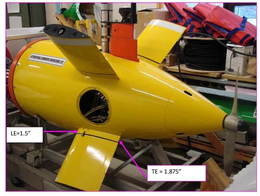
In the case of dive planes (Figure 1), the root-base projects out by 1.5 inches (equivalent to 3.8 cm), which may be added to the span of the fin (14”~36 cm). This thickness is uniform along the length of the chord. It is fixed and does not deflect with the fins [19].
As can be seen in Figure 2, the root-base for the stern plane is not of uniform thickness throughout the length of the chord compared to the case of dive planes. In order to account for the curvature of the faired tail section, the root-base has a leading-edge thickness of 1.5” (same as previous) but a trailing edge (TE) thickness of 1.875”. In any case, the root base is fixed and does not move with the planes.
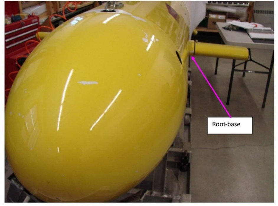
Figure 1. Dive planes of MUN Explorer
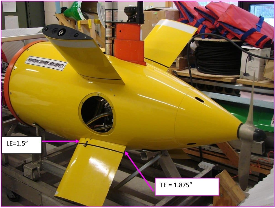
Figure 2. Stern planes (rudders) of MUN Explorer
- Sea Trials
During a typical mission, the AUV records a host of parameters that are logged onto the Vehicle Control Computer (VCC) hard drive. These parameters include information on vehicle position, attitude, heading, and speed, propeller rpm. depth, altitude, control plane deflections, and power input to various sensors, and actuators to name a few.
To perform a helix, the AUV performs a circle and then a “dive-and-turn” phase by which it descends to the next circular path in a larger depth. The two bow planes are engaged during the dive-and-turn phase and have a non-zero value for about 10 seconds [16] Figure 4 100.
Figure 3 to Figure 6 show sample maneuvering of MUN Explorer during a sea trial [20]. During a plane turning circle, a positive deflection angle means that the leading edge (LE) of the bow planes (dive planes) turn upward, thus they produce a net upward force, while the four stern planes produce a net downward force. Planes number 3 (upper port) and 6 (lower starboard) use  and planes 4 (lower port) and 5 (upper starboard) use
  to perform a starboard turn [21].
Given the command radius and speed, the control plane deflections necessary for achieving a circle having the command radius are automatically determined and set by the vehicle control system during the mission execution. The position of the vehicle is estimated by DVL using velocity and heading.
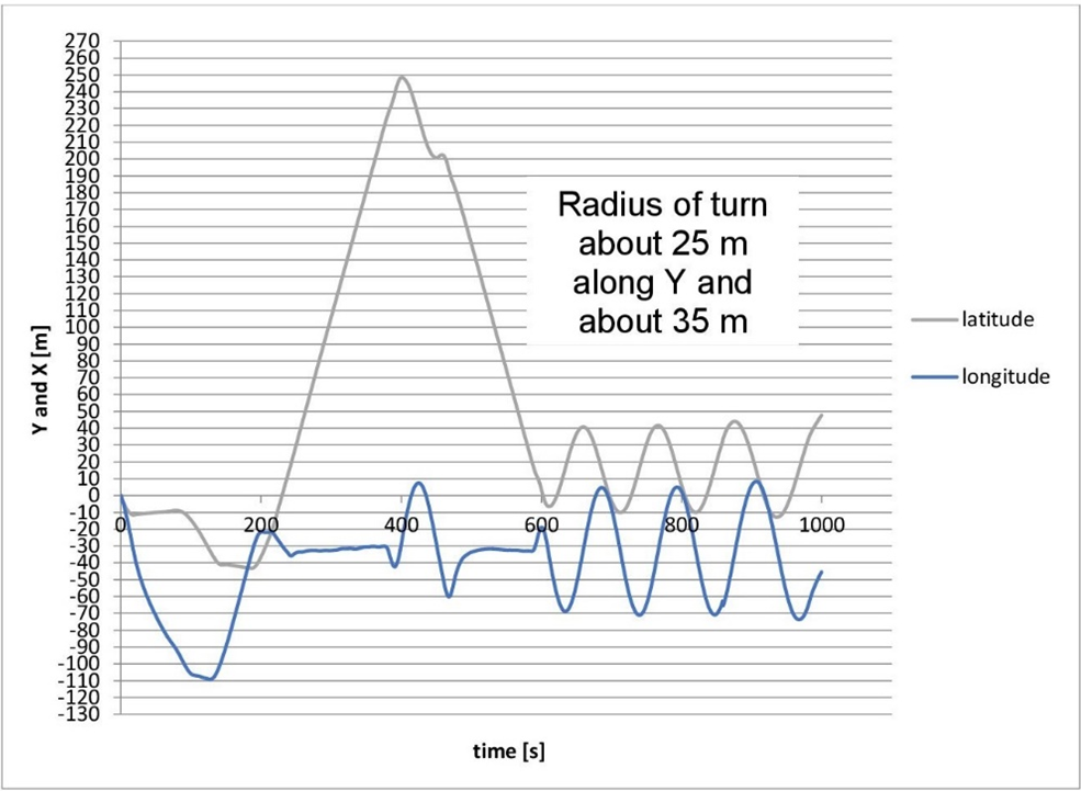
Figure 3. Time history of vehicle position
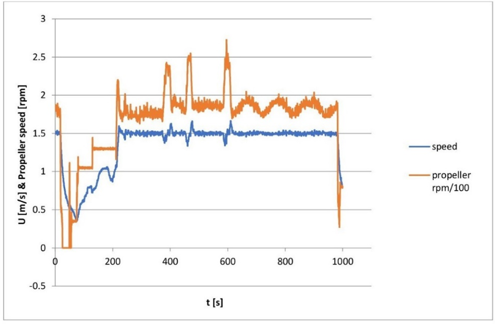
Figure 4. Vehicle and propeller speed
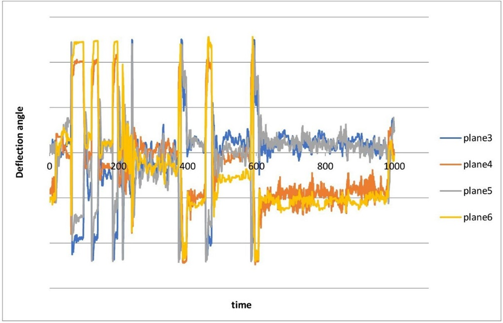
Figure 5. Deflection angles of the stern planes
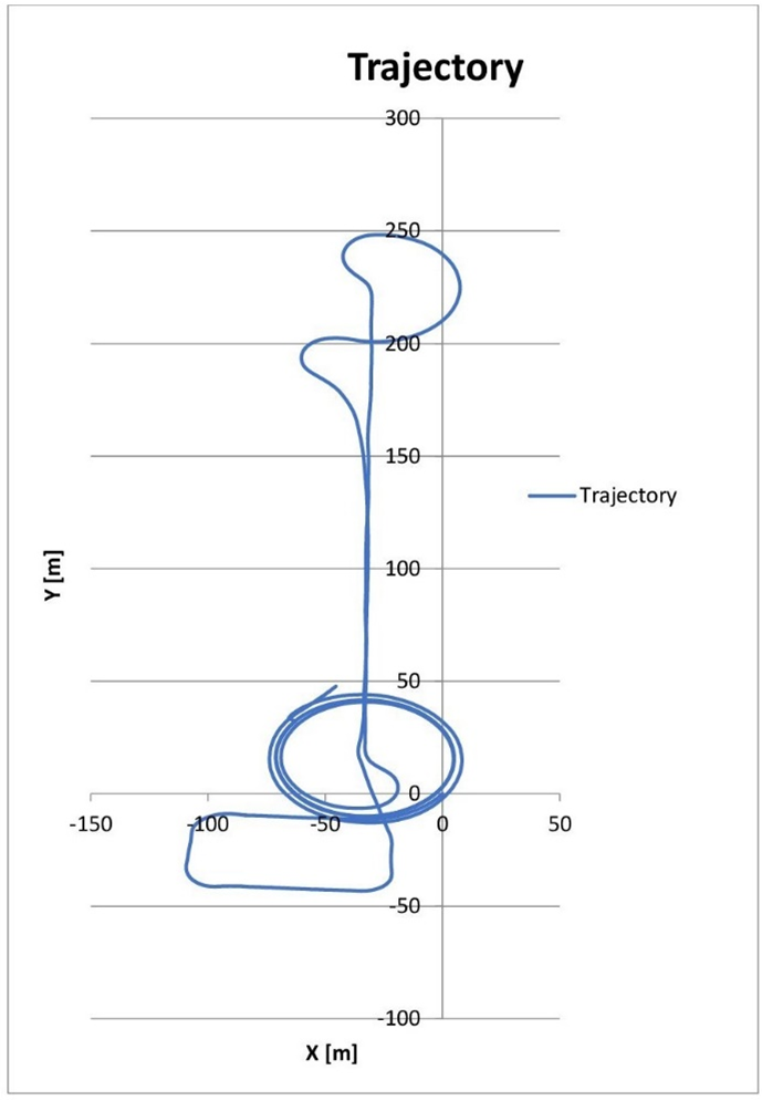
Figure 6. Vehicle trajectory
- Roll Control Adverse Yaw
Roll control adverse yaw is a phenomenon that occurs when an aircraft rolls to one side, but also yaws in the opposite direction. This is due to the difference in lift generated by the two wings. When the aircraft rolls to one side, the wing that is tilted up generates more lift than the wing that is tilted down. This difference in lift causes the aircraft to yaw in the opposite direction. Pilots can counteract adverse yaw by using the rudder. When the pilot applies a rudder, the aircraft will yaw in the direction of the rudder deflection.
Adopted by the author the Roll Control application [22] is a simplified AUV subsystem that is in charge of:
- Calculating the vehicle roll rate according to a rudder command and the adverse yaw effect from both dive planes (and possibly the hull’s added moment of inertia effect);
- Computing left and right warning alarms, which sound, respectively if the vehicle roll rate is strictly less than –10.0° per second or strictly greater than 10.0° per second;
- Computing the “roll mode” (either Off, Nominal, or Failsoft) according to the ON/OFF button being pressed and the vehicle roll rate value.
Active control of the vehicle toward target parameters that are unknown before deployment, such as where the target is or where the target is headed is achieved by using in-situ data analysis in real-time with an additional on-board computer called a backseat driver. This computer sends instructions to modify the mission of the vehicle and to promote its autonomy [14], [23].
To give the underwater vehicle the ability to mitigate problems autonomously by onboard fault protection system, [24] use a combination of BNP {Bayesian nonparametric} and LDA {Latent Dirichlet allocation} techniques. The developed model is used for fault diagnosis in AUV vertical plane maneuvers. The existing data-driven methods do not grow and have rigid structures. It is helpful for the UUV type of performance to evolve its intelligence by using new data as it undergoes new operation modes. Therefore, it is necessary to automatize:
- The system characters and patterns, and
- The system nominal and fault mode adaptability.
This process is described by [24] as a transformation of records of the AUV’s sensors which are heterogenous data (e.g., numeric, Boolean, or text) to a common domain space. They assume that there are an infinite number of latent {unknown} topics, but only a finite number of them is enough to explain the observed data. Then, the smart robot can upgrade with the size and complexity of the data. Therefore, article [24] is an illustration of how the automated vehicle can enhance its database for failure and faults.
Figure 7 shows the computer model in Ansys SCADE™. As can be seen, the major elements in this virtual model transit from where a failure may lead to an adverse maneuvering status for the automated vehicle. It is analogous to an event tree analysis where the sequence of events and their hazards can be logically traced.
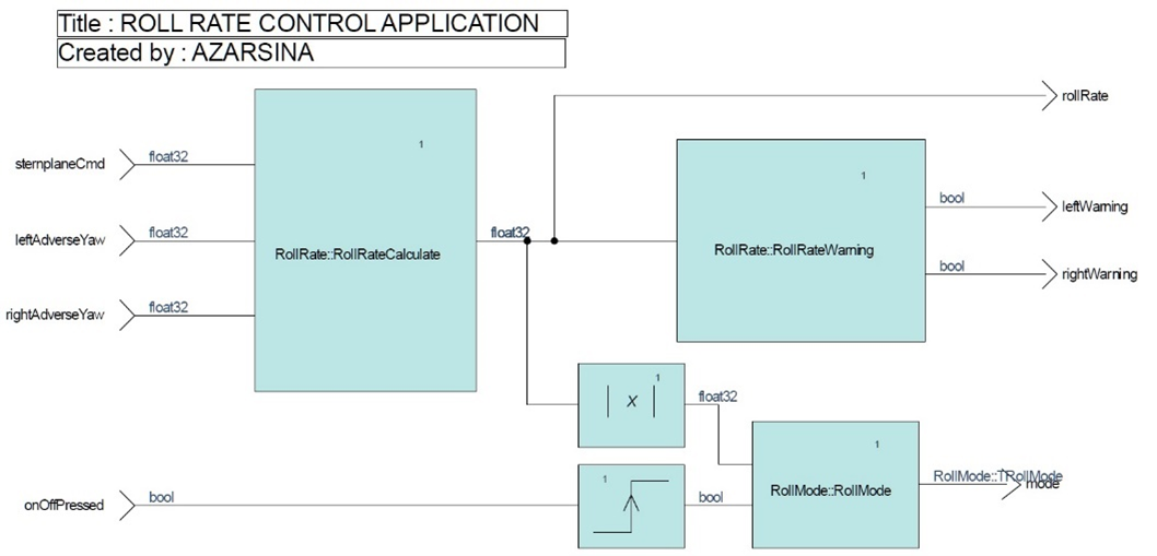
Figure 7. Roll control adverse yaw computer application [22]
- RESULT AND DISCUSSION
The dependability of system structures can be modeled using dependability block diagrams (DBD), similar to reliability block diagrams (RBD). According to the binary basis of the Boolean logic, the DBD is either in the up state mode or in the down state mode. Each network model can be converted from the up state mode into the down state mode using the Boolean algebra:  , and vice versa:
  [8]. The system down state is a logical OR-connection of all minimal cuts MC, while the system up state is the AND-connection of their negation
  , modeled by DBD belonging to the system S: [8]
| 
| (1) |
For each component (e.g., computer, communication line), the following three states are defined. U up state (processing/delivering of the correct message within time). D down state (no processing/delivering of the message or message out of time, e.g., due to failure of a computer, breakage of transport line, etc.). F fault message state (processing/delivering of the faulty message, e.g., faulty processing or transferring of the incorrect message, falsified or corrupted message). It is assumed that the components are s-independent; stochastic dependency (s-dependency) is explained by [8].
| 
| (2) |
- System Requirement Analysis
To be able to compensate the vehicle path by the application of the X-planes at the vehicle stern, they act sequentially. As a result, they are modeled as four components that are connected in series. It was seen in Figure 5, that the X-planes during a turning maneuver take values that fluctuate about an average. All turns were performed to the starboard side [16]. As long as the four planes are acting the maneuvering objective is fulfilled. If any of the four planes fail, then the vehicle can no longer follow the prescribed trace. Figure 8 is a 3D sketch of what shall happen during a successful oil spill crisis scenario as defined in this article. While the AUV is aiming to stay in the turn an adverse effect of the bow planes can stray it outside the desired path.
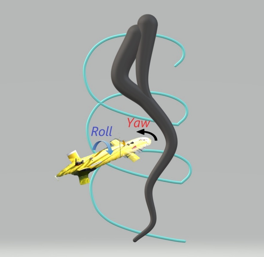
Figure 8. Upward spiral (helix) maneuver around an oil plume
- Objective System States
System states are as follows,  up state means that the X-planes give the correct input for roll control.
  down state means that the X-planes cannot contribute to roll control.
  fault state (running: in [25] the states are either success, failure, or running. The latter means that the action is running.) means that the X-planes are running but the resulting trace goes off the prescribed trajectory due to adverse yaw effect. We define according to [8]:
| 
| (3) |
| 
| (4) |
- Component Modeling
Each of the four planes is a component of this subsystem which covers a part of the overall roll control task. All parameters of the components are assumed to be the same.
The dependability of each control plane depends (1) on the proper calculation and delivery of the control signal to it, and (2) on the proper mechanical actuation of the plane.
Figure 9 illustrates the model of the components: each plane has an actuating time before and after which the vehicle control computer is communicated to and from. The VCC (nodes) are not considered in the component model, as it is assumed to be 100% dependable).
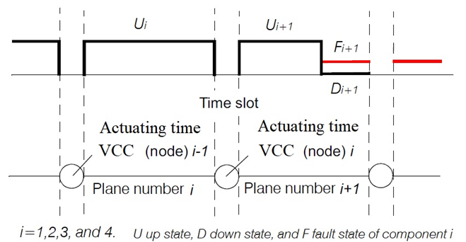
Figure 9. Illustration of the component model (four components)
The following three states are defined for each of the components,  up state (actuation of the correct hydrodynamic force from one node to the next within a given actuating time) ɟ,
  = 0.979 probability of the up state.
  down state (no actuation of the planes due to failure of the component, e.g. gears stuck, electric lines broke, or exceedance of actuating time),
  = 0.02 probability of the down state. According to [26] it is known that there have been not many instances of a down state. There have been instances when fish (squid) or large kelp have obstructed/constrained plane movement. 2% is likely reasonable.
  fault state (running of fault actuation, e.g., wrong order of actuation, coupling of motions, corruption of signal),
  = 0.001 probability of the fault state. ɟ NOTE: The VCC log counter of MUN Explorer operates at 0.1 seconds [20], however the actuating time in Figure 9 is not necessarily the same. The logic of a linear controller would be to adjust the command angles of the four planes one after the other in the order of their numbering 3 to 6 (X-planes). The exact calculation of dependability is as follows:
| 
| (5) |
- CONCLUSIONS
Finding the underwater patches of an oil spill by an AUV and gathering information urgently and accurately can assist in confining the pollution within a region which is a vital step in responding to the incident. The task constitutes sensing and detecting the environment and at the same time motion planning and control which requires hardware-in-the-loop simulation [27]. Originating in aviation, an adverse yaw effect was assumed to cause undesirable changes in the heading of an underwater vehicle. As was seen in Figure 8 the AUV uses its dive planes to heel to the helix maneuver. Due to unbalanced lift forces of the port and starboard planes, an adverse yaw moment can appear. In such circumstances, the manuscript demonstrated how sensitive the vehicle control system is to failure or fault. About 90% of the time, the helix run is successful. “Detailed analyses have mostly uncovered that system failures are caused by inadequate system design and s-dependencies between components, often triggered by common cause failures (CCF) or, in the worst case, by systematic failures” [28]. In our problem, small thrusters compared to a single propeller can in addition to producing thrust force, contribute to course keeping. For example, four thrusters like the arrangement of the Russian MT class AUV [29] or the French Alistar 3000 AUV [30] make a control system that can work parallel to the rudder system. Better dependability comes at the price of a more complex system, however. The Markov minimal cut approach [28] can assist in resolving the transitions and finding system down states. This could be the suggested mainstream for future research.
ACKNOWLEDGEMENT
The author cordially thanks Mr. Ron Lewis from MERLIN and Professor Neil Bose from Memorial University of Newfoundland who through email responses helped in completing the manuscript contents. Continued support of Dr. Xuwen Feng and the ISO TC 8/ SC 13 Marine Technologies team at the Second Institute of Oceanography, Ministry of Natural Resources, PRC is truly appreciated. This research could not happen without the caring support of WG 1 Submersibles coordinator, Ms. Yao Wang, and its respectable convener Mr. Cong Ye.
REFERENCES
- ISO, “ISO/AWI 20682 Autonomous Underwater Vehicles Risk and Reliability,” 01 06 2023. [Online]. Available: https://www.iso.org/standard/86398.html. [Accessed 03 02 2024].
- M. P. Brito dan G. Griffiths, “A Markov chain state transition approach to establishing critical phases for AUV reliability,” IEEE Journal of Oceanic Engineering, vol. 36, no. 1, pp. 139-149, 2011, https://doi.org/10.1109/JOE.2010.2083070.
- M. Allocco, Safety analyses of complex systems: considerations of software, firmware, hardware, human, and the environment, Hoboken, New Jersey: Willey, 2010.
- ISO 23460, Space projects — Programme management — Dependability assurance requirements, GENEVA: ISO, 2011.
- C. Thieme, Development of a Risk Management Process for NTNU's REMUS 100 AUV, Trondheim, Norway: Norwegian University of Science and Technology, 2014.
- M. P. Brito dan G. Griffiths, “Updating Autonomous Underwater Vehicle Risk Based on the Effectiveness of Failure Prevention and Correction,” JOURNAL OF ATMOSPHERIC AND OCEANIC TECHNOLOGY, vol. 35, pp. 797-808, 2018, https://doi.org/10.1175/JTECH-D-16-0252.1.
- F. Maurelli, S. Krupinski, X. Xiang dan Y. Petillot, “AUV localisation: a review of passive and active techniques,” International Journal of Intelligent Robotics and Applications, vol. 6, pp. 246-269, 2022, https://doi.org/10.1007/s41315-021-00215-x.
- H.-D. Kochs, System Dependability Evaluation Including S-dependency and Uncertainty: Model-Driven Dependability Analyses, Cham, Switzerland: Springer International Publishing AG, 2018, https://doi.org/10.1007/978-3-319-64991-7.
- X. Chen, N. Bose, M. Brito, F. Khan, B. Thanyamanta dan T. Zou, “A review of risk analysis research for the operations of autonomous underwater vehicles,” Reliability Engineering and Systems Safety, vol. 216, pp. 1-17, 2021, https://doi.org/10.1016/j.ress.2021.108011.
- P. Koopman, “A User’s Guide to Vehicle Automation Modes,” 28 01 2021. [Online]. Available: https://edgecaseresearch.medium.com/a-users-guide-to-vehicle-automation-modes-4bdd49b30dc0. [Accessed 30 05 2023].
- M. Gad-el-Hak, “Coherent structures and flow control: genesis and prospect,” BULLETIN OF THE POLISH ACADEMY OF SCIENCES, vol. 67, no. 3, pp. 411-444, 2019, https://doi.org/10.24425/bpasts.2019.129644.
- D. Mercado, M. Maia dan F. J. Diez, “Aerial-Underwater Systems, a New Paradigm in Unmanned Vehicles,” Journal of Intelligent & Robotic Systems, pp. 1-10, 2018, https://doi.org/10.1007/s10846-018-0820-x.
- A. Dawson, P. Graziani dan E. Miller, Interviewees, All things Ansys- PADT podcast: Episode 83. [Interview]. March 2020.
- J. Hwang, N. Bose, H. Nguyen dan G. Williams, “Oil plume mapping: Adaptive Tracking and adaptive sampling from an autonomous underwater vehicle,” IEEE Access, vol. 8, pp. 198021-198034, 2020, https://doi.org/10.1109/ACCESS.2020.3032161.
- N. Bose, “Canadian Academy of Engineering Oceans Seminar,” Canadian Academy of Engineering, St. John's, 2021.
- M. T. Issac, Analysis of Full-Scale Sea-Trials Manoeuvring Data and Development and Validation of a Motion-Simulation Model for the AUV "MUN Explorer", St. John's: Memorial University of Newfoundland, 2011.
- MUN, “Memorial University of Newfoundland and Labrador,” 2023. [Online]. Available: https://www.mun.ca/engineering/research/centres-and-facilities/research-centres/oerc/facilities/merlin/explorer-auv/. [Accessed 16 11 2023].
- R. Lewis, N. Bose, S. Lewis, P. King, D. Walker, R. Devillers, N. Ridgley, T. Husain, J. Munroe dan A. Vardy, “MERLIN - A decade of large AUV experience at Memorial University of Newfoundland,” dalam IEEE/OES Autonomous Underwater Vehicles (AUV), Tokyo, 2016, https://doi.org/10.1109/AUV.2016.7778675.
- C. D. Williams, “Email communications,” NRC Canada, St. John's, 2009.
- Explorer, “Holyrood sea trials,” Azarsina, Farhood, St. John's, 2023.
- F. Azarsina, Experimental Hydrodynamics and Simulation of Manoeuvring of an Axisymmetric Underwater Vehicle, St. John's: Memorial University, 2009.
- ROLL RATE CONTROL APPLICATION: RollControl SCADE Model, 2024.
- J. Hwang, N. Bose, G. Millar, C. Bulger dan G. Nazareth, “Bubble Plume Tracking Using a Backseat Driver on an Autonomous Underwater Vehicle,” Drones, vol. 7, pp. 1-21, 2023, https://doi.org/10.3390/drones7100635.
- B.-Y. Raanan, J. Bellingham, Y. Zhang, M. Kemp, B. Kieft, H. Singh dan Y. Girdhar, “Detection of unanticipated faults for autonomous underwater vehicles using online topic models,” Journal of Field Robotics, pp. 705-716, 2017, https://doi.org/10.1002/rob.21771.
- C. I. Sprague, Ö. Özkahraman, A. Munafo, R. Marlow, A. Phillips and P. Ögren, "Improving the Modularity of AUV Control Systems using Behaviour Trees," 2018 IEEE/OES Autonomous Underwater Vehicle Workshop (AUV), pp. 1-6, 2018, https://doi.org/10.1109/AUV.2018.8729810.
- R. Lewis, “Email communication,” Memorial University, St. John's, 2024.
- J. Evans dan D. Lane, “Distributed hardware-in-the-loop simulation for unmanned underwater vehicle development—issues and applications,” dalam Technology And Applications of Autonomous Underwater Vehicles, pp. 1-18, 2003, https://doi.org/10.1201/9780203522301.ch1.
- H.-D. Kochs, Dependability of Engineering Systems: A Markov Minimal Cut Approach, Cham, Switzerland: Springer , 2020, https://doi.org/10.1007/978-3-030-38327-5.
- L. V. Kiselev, A. V. Bagnitckii dan A. V. Medvedev, “Identification of AUV Hydrodynamic Characteristics Using Model and Experimental Data,” Gyroscopy and Navigation, vol. 8, no. 3, pp. 78-92, 2017, https://doi.org/10.1134/S2075108717030051.
- D. Scourzic, “Alistar AUV on track for inspection trials in the Gulf of Mexico,” Offshore Magazine, [Online], p. 01, April 2006.
AUTHOR BIOGRAPHY

| Farhood Azarsina, since 2009 works as a full-time faculty member at Islamic Azad University, Science and Research Branch located in Tehran. His research interests are marine dynamics, hydrodynamics, and underwater science and technology. He completed his doctoral studies at Memorial University of Newfoundland at the time when the university had just owned the autonomous underwater vehicle that is the research instrument of the present article. Azarsina studied bachelor and master of science in mechanical and marine engineering at Sharif University of Technology. |
Dependability of the Explorer Autonomous Underwater Vehicle in Oil Plume Response Mission; Case Study of the Vehicle Roll Control (Farhood Azarsina)