Scientific Bulletin of Bachelor of Electrical Engineering ISSN: 2685-9572
Design of PIFA Antenna Using Systematic Tuning for Long Range Communication
Perancangan Antena PIFA Menggunakan Penalaan Sistematis untuk Komunikasi Long Range
Liya Yusrina Sabila 1 , Teguh Prakoso 2 , Munawar Agus Riyadi 3
1 Program Studi Teknik Elektro, Universitas Ahmad Dahlan, Indonesia
2,3 Program Studi Teknik Elektro, Universitas Diponegoro, Indonesia
ARTICLE INFORMATION |
| ABSTRACT / ABSTRACT (10 PT) |
Article History/History: Posted 01 Jun 2019 Revised July 01, 2019 Accepted 01 August 2019 (Leave this part alone) |
| Komunikasi dengan sistem tanpa kabel merupakan salah satu komunikasi yang menjadi andalan sehingga integrasi komunikasi tercapai. Dalam penerapan ini, tentunya membutuhkan antena untuk mengirimkan gelombang informasi ke penerima. Antena juga diharapkan dapat diintegrasikan dengan komponen lain menjadi sebuah sistem terintegrasi. Ada beberapa tantangan yang perlu dijawab untuk merealisasikan hal ini. Yaitu ukuran antena yang kecil dan bentuk antena dapat menyesuaikan bentuk dari objek yang diintegrasikan, contohnya adalah bentuk lingkaran atau silinder. Antena yang dipilih untuk merealisasikan tantangan tersebut adalah Planar Inverted F Antenna (PIFA). Antena PIFA banyak digunakan pada perangkat-perangkat komunikasi karena bentuk dan ukurannya yang dapat disesuaikan dengan dimensi perangkat tersebut. Teknik yang digunakan untuk mewujudkan bentuk melengkung adalah teknik konformal. Untuk mengefisiensikan langkah perancangan antena, metode penalaan sistem diterapkan saat mensimulasikan perancangan. Hasil yang dicapai menggunakan metode penalaan sistem yang dapat memperingkas langkah percobaan menjadi 6 langkah percobaan saja. Antena yang dirancang bekerja rentang frekuensi 916,9 – 933 MHz, frekuensi resonansi 925,6 MHz dengan S11 adalah -12,5 dB, bandwidth 16,1 MHz, dan pola radiasi omnidirectional . Communication with a wireless system is one of the mainstays of communication so that communication integration is achieved. In this application, of course, an antenna is needed to send information waves to the receiver. It is also hoped that the antenna can be integrated with other components into an integrated system. There are several challenges that need to be answered to make this happen. Namely, the size of the antenna is small and the shape of the antenna can adjust to the shape of the object being integrated, for example a circle or cylinder shape. The antenna chosen to realize this challenge is the Planar Inverted F Antenna (PIFA). PIFA antennas are widely used in communication devices because their shape and size can be adjusted to the dimensions of the device. The technique used to create curved shapes is a conformal technique. To streamline the antenna design steps, the system tuning method is applied when simulating the design. The results achieved use a system tuning method which can reduce the experimental steps to just 6 experimental steps. The antenna designed works in the frequency range 916.9 – 933 MHz, the resonant frequency of 925.6 MHz with S11 is -12.5 dB, bandwidth 16.1 MHz, and the radiation pattern is omnidirectional. |
Keywords/Keywords: PIFA; Conformal; Tunning; 900 MHz; Long Range
|
Corresponding Author/Corresponding Author: Liya Yusrina Sabila, Universitas Ahmad Dahlan, Yogyakarta, Indonesia. liya,sabila@te.uad.ac.id |
This work is licensed under a Creative Commons Attribution-Share Alike 4.0 
|
Citation of this Document / Citation Document: (Leave this part) Author 1 and Author 2, “Title,” Scientific Bulletin of Undergraduate Electrical Engineering , vol. 3, no. 1, pp. xx-xx, 2021. DOI: 10.12928/biste.v3i1.xxx |
- INTRODUCTION / INTRODUCTION
Telecommunication technology using cable media (wireline) has now begun to be abandoned and replaced with wireless technology which uses radio waves as a transmission medium. Communication with a wireless system is one of the mainstays of communication so that communication integration is achieved [1], [2]. The development of technology and information always occurs rapidly so that humans need adequate facilities. The communication facilities and infrastructure needed are of course to meet the communication needs between two or more people at any location and time . A telecommunication system without cables or what is called wireless is a system that connects devices without a cable and is replaced with electromagnetic waves [3], [4]. In this application, of course, an antenna is needed so that the waves sent and received can be achieved in this system [5], [6].
One antenna that can be used is PIFA. PIFA is widely used in communication devices because its shape and size match the dimensions of the device, such as cellphones and modems. PIFA has several advantages, such as its relatively light weight and relatively small dimensions, its radiation pattern is omnidirectional, its production costs are low, and its structure is simple and easy to modify [7]–[10]. However, PIFA also has a number of disadvantages, such as low efficiency, relatively narrow bandwidth and working on one frequency [11]. Therefore, PIFA development can be done by modifying its structure or shape to compensate for its deficiencies or to produce desired characteristics. In general, PIFA consists of a groundplane, patch, probe or shorting pin that connects the patch to the groundplane [12]–[14]. Sandra Costanzo et al [15] designed an antenna that covers the needs of the Medical and Wireless Body Area Sensor Network, namely at a frequency of 2.36 GHz. The created antenna shows an increase of 3 dB. Guoping Gao et al [16] designed an antenna at the 2.4 GHz frequency for wearable applications. The antenna that produces the return loss is designed to be around -30 dB with a gain of 6.72 dBi.
In antenna design, researchers often use the trial and error method to get maximum results. This method has a weakness, it does not have a benchmark or size reference and can result in many steps having to be taken. This research improves the steps in design so that become more systematic by using a systematic tuning method. Systematic tuning is one of the methods used in experiments in the form of a systematic approach to determine the ideal conditions for a production process with the minimum possible reject rate. It can also be interpreted as an experimental technique that helps to investigate the best combination of parameters to be changed in order to obtain reliable static results. The systematic tuning method uses a benchmark or reference size of ±5% of the nominal size. The next step is to determine the parameters that influence antenna performance.
The research that will be carried out is designing an antenna that can be used for long distance communications, at a frequency of 900 MHz. In accordance with Internet of Things (IoT) technology, long range communications can use Sigfox or LoRa technology which works at a frequency of 900 MHz [17]–[19]. LoRa is a wireless communication system for the Internet of Things, offering long distance communication (> 15 km in remote areas) and low power. Antenna design has its own challenges when it needs to be placed on a surface that is not flat or curved, such as a circle or cylinder. So that the antenna can be placed well on a curved surface, the antenna is designed using conformal techniques to give it a curved shape. With a conformal antenna shape, it will be easier to install in areas that have a curved shape. The antenna used in wireless communication is not only the most important part, but also the main design and implementation problem that affects the performance of the wireless communication system [20]–[22]. This research aims to design an antenna with a small size that can be constructed onto other objects in a circular or cylindrical shape and has good performance in terms of bandwidth, S11, and resonant frequency.
- RESEARCH METHODS
In PIFA design, there are five important stages that will be followed, determining antenna specifications, determining antenna dimensions, carrying out design by tuning the system and analyzing the performance of the antenna design.
2.1 Antenna Specifications
Antenna specifications are something that is important to do at the beginning to meet the required performance. Specifications are determined from market needs. Antennas with a frequency of 900 MHz are designed to have the following specifications:
- Frequency Range : 919 MHz – 925 MHz
- Resonance Frequency: 922 MHz
- Bandwidth: 6 MHz
- S 11 : ≤ 10 dB
- Radiation Pattern : Omnidirectional
The antenna chosen is PIFA. PIFA has been widely used in mobile communication systems as mobile phones and laptops because of its compact design and is widely used in small portable devices. PIFA is like a monopole printed on a PCB, but has shorting feed points along the main resonance structure shown in Figure 1. The shorting feed point configuration can reduce the size of the antenna.
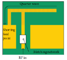
Figure 1. Planar inverted -F antenna (PIFA)
2.2. Initial Design of Antenna
The nominal design of the antenna is in Figure 2 and the dimensions are in Table 1. Initial results for the antenna are shown in Figure 3, showing that the resonance frequency does not meet the specifications, that is 922 MHz. Therefore, there is a need for a tuning process to get maximum results.


Figure 2. PIFA design
Table 1. Size of initial design of antenna
Variable | Size (mm) |
Ls | 20.7502 |
Ps | 28.53 |
Wp | 10.23 |
Lp | 15 |
Lf | 15 |
G | 0.9502 |
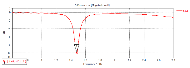
Figure 3. Initial results of PIFA design
2.3 Design Using Conformal Techniques
The antenna varied in curvature with a radius of 25 mm. Figure 4 is a simulation of the antenna when it is varied using conformal techniques and Figure 5 is a simulation of the antenna when it is added with other materials, namely silicon. Silicone was chosen as another material because it refers to the material used in proesthetic hands. Proesthetic hands are known to have a curved shape and use materials, one of which is silicon. Conformal techniques are used to meet the need for curved antennas to adjust when the antenna is integrated with a cylindrical or circular plane.
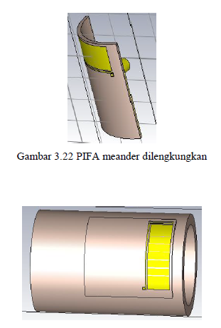
Figure 4. PIFA with conformal technique
Figure 5. PIFA with silicone material
The simulation results in Figure 4 and Figure 5 are tabulated in Table 2. Differences occur when the antenna is varied conformally in the form of a shift in frequency and S11 value. However, this time the difference looks more prominent. When applied with additional material the S11 value improves but the frequency range shifts to a lower frequency. So the antenna needs to be tuned again to get a frequency of 922 MHz. A comparison of the results of the original flat, conformal PIFA and the influence of the bionic hand can be seen in Table 2. The frequency range and bandwidth of the antenna shape when applied to the bionic hand are not written because the upper and lower frequency limits do not have an S11 value of less than -10 dB.
Table 2 . Size of initial design of antenna
Specification | Flat | Conformal | Additional Other Materials |
Frequency Range | 1475 – 1493 MHz
| 1387 – 1409 MHz | - |
Resonance Frequency | 1480 MHz | 1397 MHz | 1139 MHz |
Bandwidth | 8.2 MHz | 22.4 MHz | - |
S11 | -10.2 dB | -11.7 dB | -4.7 dB |
Table 2 shows the influence of antenna performance on the conformal shape and the addition of other materials. From experiments on flat shapes, third conformal shapes and additional materials have not shown performance in accordance with the specified specifications. Therefore, it is necessary to optimize using system tuning.
- RESULTS AND DISCUSSION / RESULTS AND DISCUSSION
In the systematic tuning process there are four variables that will be varied in the CST simulation, there is Lf, G, Lp and Wp. These four variables determine the number of experiments that must be carried out. For each factor a value of -1 and +1 is set as shown in Table 3. The value in Table 3 represents ±5% of the nominal value. The (-1) label represents a -5% variation and the (+1) label represents a +5% variation from the nominal value of the component.
Table 3 . Size of initial design of antenna
Variable | -1 | +1 |
Lf | 14.25 | 15.75 |
G | 0.9027 | 0.9977 |
Lp | 14.25 | 15.75 |
Wp | 9.7185 | 10.7415 |
3.1. Interaction Between Variables on Response
Response is the parameter that will seek the best results. The response used is the resonant frequency and S11. The relationship between response and antenna size variables is obtained from data processing using Minitab software. Figure 6 is the result of an analysis of interactions between variables that influence each response using systematic tuning by taking significant factors that have a slope above 0.005 for the frequency response and 0.07 for the S11 response. If we want to change the resonant frequency, then we can choose the parameter to be changed, namely Lp, f or Lf, as well as S11.
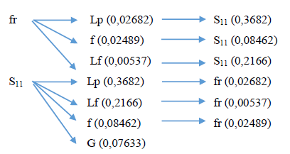
Figure 7. Interaction Tree Diagram Between Factors
3.2. System Tuning
Tuning 1
The tuning process is carried out to adjust the antenna performance. In this case adjust the resonant frequency and S11 with several tuning steps. The center frequency ( 𝑓 r) of 1139 MHz will be shifted to 922 MHz. According to the tree diagram, the most significant factor for shifting frequency is Lp with a coefficient of 0.02682 for every -5% change in nominal length. In order for the frequency to shift to 922 MHz, Lp must be changed by 40.4549%. If 40.4549% of 15 mm is 6.0682 mm. Then Lp becomes 15 + 6.0682 = 21.0682 mm. From tuning 1 you can shift the frequency to 927.8 MHz .
Tuning 2
In tuning 2, changes are made to Lf with a coefficient of -0.2166 for every change of +5% of the nominal length. The coefficients used in this case are the two coefficients of Lp and Lf, being -0.5848. In order for the S11 value to be -20 dB, Lf must be changed by 142.6171% from 15 mm, namely 21.3926 mm. Then Lp becomes 15 + 21.3926 = 36.3926 mm. Tuning 2 has the effect of changing the S11 value to -16.7 dB with a FR of 971.8 MHz.
Tuning 3
In the 3rd tuning it will shift the resonant frequency ( 𝑓 r) again because it is still not in accordance with the planned specifications, namely 922 MHz. Wp is selected as the variable to be changed. In the previous tuning, changes were made to Lp and Lf, so the coefficients used were these three coefficients, becoming 0.0571. Wp should be changed by 4.3624%. Where 4.3624% of 10.23 is 0.4463 mm. So, Lf becomes 10.23 + 0.4463 = 10.6763 mm. Tuning 3 has the effect of shifting the frequency to a lower frequency, namely 956.4 MHz and an S11 value of -15.7 dB.
Tuning 4
The center frequency on S11 ( 𝑓 r) of 956.4 MHz will be shifted to 922 MHz. In tuning 4, the Lp changes are made. The coefficient of frequency response used is twice Lp, Lf, and f, being 0.0839. In order for fr to shift to 922 MHz, Lp must be changed by 2.05% from 21.0682 which is 0.4319 mm. So, Lp becomes 21.0682 + 0.4319 = 21.5002 mm. Tuning 4 is able to shift the resonant frequency to 941 MHz with S11 of -16.8 dB.
Tuning 5
In tuning 5, the Lp is changed again to shift the frequency to 922 MHz . In tuning 5, the same coefficient as tuning 4 is used by adding Lp, to 0.11072. Lp must be changed by 0.858% from 21.5002 which is 0.1845 mm . So, Lp becomes 21.5002 + 0.1845 = 21.6846 mm. Tuning 5 has the effect of shifting the frequency to 934.4 MHz and has an S11 value of -18.2 dB.
Tuning 6
The center frequency on S11 ( 𝑓 r) of 934.4 MHz will be shifted to 922 MHz. In tuning 6, the LP changes again. In tuning 6, the same coefficient as tuning 5 is used by adding Lp, to 0.1375. In order for fr to shift to 922 MHz, Lp must be changed by 0.451% from 21.6846 which is 0.0978 mm. So, Lp becomes 21.6846 + 0.0978 = 21.7824 mm. Tuning 6 is carried out by changing the Lp value to 21.7824 mm and has the effect of shifting the fr to 925.6 MHz and has an S11 value of -12.5 dB.
Table 4 shows the tuning stages carried out and Figure 8 shows the final results of S11. In this case, tuning stops at tuning 6 because at tuning 6, the antenna performance already meets the specified specifications. The comparison of the resonant frequency and S11 for each tuning is tabulated in Table 5. The resulting frequency range is 916.9 – 933 MHz and the omnidirectional radiation pattern is shown in Figure 9 and Figure 10. So it can be said that the Original PIFA for a frequency of 900 MHz meets the specifications. Figure 9 and Figure 10 show that the omnidirectional radiation pattern is fulfilled due to the circular shape of the radiation area spreading in all directions, not just in one direction, so it can receive waves or signals from any direction.
Table 4 . Systematic tuning process
Variable | Nominal | Tuning 1 | Tuning 2 | Tuning 3 | Tuning 4 | Tuning 5 | Tuning 6 |
Lf | 15 | 15 | 36.3926 | 36.3926 | 36.3926 | 36.3926 | 36.3926 |
G | 0.9502 | 0.9502 | 0.9502 | 0.9502 | 0.9502 | 0.9502 | 0.9502 |
Lp | 15 | 21.0682 | 21.0682 | 21.0682 | 21.5002 | 21.6846 | 21.7824 |
Wp | 10.23 | 10.23 | 10.23 | 10.6763 | 10.6763 | 10.6763 | 10.6763 |
Tabel 5. Comparison of the results of each tuning
Spesifikasi | Nominal | Tuning 1 | Tuning 2 | Tuning 3 | Tuning 4 | Tuning 5 | Tuning 6 |
Resonance Frequency | 1139 MHz | 927,8 Mhz | 971,8 MHz | 956,4 MHz | 941 MHz | 934,4 MHz | 925,6 MHz |
S11 | -4,7 dB | -3,3 dB | -16,7 dB | -15,7 | -16,8 | -18,2 | -12,5 |
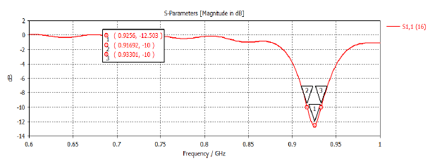
Figure 8. Final S11 results
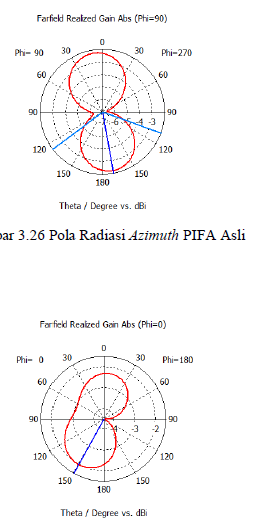
Figure 9. PIFA Azimuth Radiation Pattern
Figure 10. PIFA Elevation Radiation Pattern
3.3. Antenna Performance Evaluation
Based on the systematic tuning process up to tuning 6, it shows that the PIFA plan can meet the specified specifications. It can be seen in Table 6 that PIFA has the appropriate bandwidth and S11 values. From the experiments that have been carried out, the final antenna design meets the required performance. It can be seen that the antenna design in this research has performance that is in accordance with the references provided. This means that the antenna that has been designed can then be implemented.
Table 6. Antenna Performance
Specification | Flat PIFA | Conformal PIFA |
Frequency Range | 919 – 925 MHz | 916.9 – 933 MHz |
Resonance Frequency | 922 MHz | 925.6 MHz |
Bandwidth | 6 MHz | 16.1 MHz |
S11 | ≤ - 10 dB | -12.5 dB |
Radiation Patterns | Omnidirectional | Omnidirectional |
Table 7. Comparison with The Others Antenna
Ref. | Resonance Frequency | S11 | Radiation Pattern |
[23] | 2.4 GHz | -15 dB | Omnidirectional |
[24] | 911 MHz | -10 dB | Omnidirectional |
[25] | 957.2 MHz | -16.1 dB | Omnidirectional |
This Research | 925.6 MHz | -12.5 dB | Omnidirectional |
- CONCLUSION / CONCLUSIONS
From this research it can also be concluded that by changing the shape of the antenna to a curved shape and adding other materials, there will be a shift in frequency and changes in antenna performance. For this reason, it is necessary to change the size. From research, it has been proven that using the systematic analysis shows more effective steps. Just using 6 steps can get the best results. This proves that using a systematic tuning method can increase time and step efficiency in achieving appropriate and best performance. The frequency shift from nominal size to tuning 6 is 213.4 MHz and the S11 value has a difference of 7.8 dB. The final results obtained for the resonant frequency are 925.6 MHz with a bandwidth of 16.1 MHz, S11 -12.5 dB and an omnidirectional radiation pattern. From the results obtained, the antenna design that was carried out met the required performance. So the antenna can be recommended for further exploration, realization and integration with other components and application in areas with curved shapes.
REFERENCES / REFERENCES
[1] I. F. Akyildiz, A. Kak, and S. Nie, “6G and Beyond: The Future of Wireless Communications Systems,” IEEE Access, vol. 8, pp. 133995–134030, 2020, doi: 10.1109/ACCESS.2020.3010896.
[2] Q. Wu, “4G Communication Technology Wireless Network Secure Communication,” 2021 Int. Wirel. Commun. Mob. Comput. IWCMC 2021, pp. 915–918, 2021, doi: 10.1109/IWCMC51323.2021.9498797.
[3] M. Islam and S. Jin, “An Overview Research on Wireless Communication Network,” Adv. Wirel. Commun. Networks, vol. 5, no. 1, p. 19, 2019, doi: 10.11648/j.awcn.20190501.13.
[4] S. Alfattani, “Review of LiFi Technology and Its Future Applications,” J. Opt. Commun., vol. 42, no. 1, pp. 121–132, 2021, doi: 10.1515/joc-2018-0025.
[5] H. Karami, H. Tabarsa, G. B. Gharehpetian, Y. Norouzi, and M. A. Hejazi, “Feasibility study on simultaneous detection of partial discharge and axial displacement of HV transformer winding using electromagnetic waves,” IEEE Trans. Ind. Informatics, vol. 16, no. 1, pp. 67–76, 2020, doi: 10.1109/TII.2019.2915685.
[6] S. Ghosh and D. Sen, “An Inclusive Survey on Array Antenna Design for Millimeter-Wave Communications,” IEEE Access, vol. 7, pp. 83137–83161, 2019, doi: 10.1109/ACCESS.2019.2924805.
[7] F. N. Ikechiamaka, C. Okpala, and A. Akinbolati, “Design of Compact Planer Inverted - F Antenna ( PIFA ) for Effective Mobile communication for National Security Design of Compact Planer Inverted – F Antenna ( PIFA ) for Effective Mobile Communication for National Security,” J. Emerg. Trends Eng. Appl. Sci., vol. 11, no. February, pp. 35–41, 2022.
[8] M. Ikram, Y. Wang, M. S. Sharawi, and A. Abbosh, “A novel connected PIFA array with MIMO configuration for 5G mobile applications,” 2018 Aust. Microw. Symp. AMS 2018 - Conf. Proc., vol. 2018-Janua, pp. 19–20, 2018, doi: 10.1109/AUSMS.2018.8346961.
[9] K. Kundu, A. Dubey, A. Dhama, and N. N. Pathak, “Planar inverted F Antenna, PIFA array in 5G applications,” J. Phys. Conf. Ser., vol. 2062, no. 1, 2021, doi: 10.1088/1742-6596/2062/1/012002.
[10] S. S. Saife, A. Istiaque, and M. A. Hossain, “Design and Characterization of Miniaturized Implantable PIFA Antenna for MICS Band Application,” 2020 IEEE Reg. 10 Symp. TENSYMP 2020, vol. 3210, no. c, pp. 254–257, 2020, doi: 10.1109/TENSYMP50017.2020.9230999.
[11] M. Nahas, “A Super High Gain L-Slotted Microstrip Patch Antenna For 5G Mobile Systems Operating at 26 and 28 GHz,” Eng. Technol. Appl. Sci. Res., vol. 12, no. 1, pp. 8053–8057, 2022, doi: 10.48084/etasr.4657.
[12] A. Ahmadihaji, H. Aliakbarian, N. M. Saaid, and P. J. Soh, “Design, simulation, fabrication and evaluation of a textile pifa for wearable iot application,” ECTI Trans. Comput. Inf. Technol., vol. 15, no. 3, pp. 289–302, 2021, doi: 10.37936/ecti-cit.2021153.241779.
[13] R. Kumar, L. S. Solanki, and S. Singh, “Miniature Archimedean Spiral PIFA Antennas for Biomedical Implantable Devices,” 2019 6th Int. Conf. Signal Process. Integr. Networks, SPIN 2019, no. 2, pp. 162–167, 2019, doi: 10.1109/SPIN.2019.8711600.
[14] R. Del-Rio-Ruiz, J. M. Lopez-Garde, and J. Legarda, “Planar textile off-body communication antennas: A survey,” Electron., vol. 8, no. 6, 2019, doi: 10.3390/electronics8060714.
[15] S. Costanzo and A. M. Qureshi, “Compact and wideband PIFA design for wireless body area sensor networks,” Electron., vol. 10, no. 21, 2021, doi: 10.3390/electronics10212576.
[16] G. Gao, S. Wang, R. Zhang, C. Yang, and B. Hu, “Flexible EBG-backed PIFA based on conductive textile and PDMS for wearable applications,” Microw. Opt. Technol. Lett., vol. 62, no. 4, pp. 1733–1741, 2020, doi: 10.1002/mop.32224.
[17] P. D. P. Adi and A. Kitagawa, “Performance evaluation of E32 long range radio frequency 915 MHz based on internet of things and micro sensors data,” Int. J. Adv. Comput. Sci. Appl., vol. 10, no. 11, pp. 38–49, 2019, doi: 10.14569/IJACSA.2019.0101106.
[18] A. Ikpehai et al., “Low-power wide area network technologies for internet-of-things: A comparative review,” IEEE Internet Things J., vol. 6, no. 2, pp. 2225–2240, 2019, doi: 10.1109/JIOT.2018.2883728.
[19] N. Islam, B. Ray, and F. Pasandideh, “IoT Based Smart Farming: Are the LPWAN Technologies Suitable for Remote Communication?,” Proc. - 2020 IEEE Int. Conf. Smart Internet Things, SmartIoT 2020, pp. 270–276, 2020, doi: 10.1109/SmartIoT49966.2020.00048.
[20] M. A. Jamshed, A. Nauman, M. A. B. Abbasi, and S. W. Kim, “Antenna Selection and Designing for THz Applications: Suitability and Performance Evaluation: A Survey,” IEEE Access, vol. 8, pp. 113246–113261, 2020, doi: 10.1109/ACCESS.2020.3002989.
[21] L. Dai et al., “Reconfigurable Intelligent Surface-Based Wireless Communications: Antenna Design, Prototyping, and Experimental Results,” IEEE Access, vol. 8, pp. 45913–45923, 2020, doi: 10.1109/ACCESS.2020.2977772.
[22] M. Z. Chowdhury, M. Shahjalal, S. Ahmed, and Y. M. Jang, “6G Wireless Communication Systems: Applications, Requirements, Technologies, Challenges, and Research Directions,” IEEE Open J. Commun. Soc., no. i, 2020, doi: 10.1109/OJCOMS.2020.3010270.
[23] S. Kumar et al., “A 915 MHz Wristwatch-Integrated Antenna for Wireless Health Monitoring,” 14th Eur. Conf. Antennas Propagation, EuCAP 2020, 2020, doi: 10.23919/EuCAP48036.2020.9135360.
[24] T. N. Kapetanakis et al., “Embroidered bow-tie wearable antenna for the 868 and 915 mhz ism bands,” Electron., vol. 10, no. 16, pp. 1–14, 2021, doi: 10.3390/electronics10161983.
[25] J. Gui, A. Andújar, and J. Anguera, “On the Reuse of a Matching Network for IoT Devices Operating at 900 MHz Embedding Antenna Boosters,” Electron., vol. 11, no. 8, 2022, doi: 10.3390/electronics11081267.
AUTHOR BIOGRAPHY / AUTHOR BIOGRAPHY

| Liya Yusrina Sabila received a B.Eng. degree in 2017 and a Master’s degree in engineering in 2021 from Electrical Engineering Department at Diponegoro University, Semarang, Indonesia. Currently, I am working as a Junior Lecturer and a researcher at the Electrical Engineering Department, Faculty of Industrial Technology, Ahmad Dahlan University in Yogyakarta, Indonesia. My research interests are in antenna and propagation,especially small antenna design.
|
|
|

| Teguh Prakoso received a B.Eng. degree in 2002 from Institut Teknologi Bandung, Jawa Barat, a Master’s degree in engineering in 2006 from Institut Teknologi Bandung, Jawa Barat and a PhD degree in Engineering from the Universiti Teknologi Malaysia in 2014. Currently, He is working as a Senior Lecturer and a researcher at the Electrical Engineering Department, Faculty of Engineering, Diponegoro University in Semarang, Indonesia. His research interests in antenna, wireless propagation, radio over fiber and RF/microwave circuit. |
|
|

| Munawar Agus Riyadi received a B.Eng. degree in 2000 from Institut Teknologi Bandung, Jawa Barat, a Master’s degree in engineering in 2002 from Institut Teknologi Bandung, Jawa Barat and a PhD degree in Engineering from the Universiti Teknologi Malaysia in 2012. Currently, He is working as a Senior Lecturer and a researcher at the Electrical Engineering Department, Faculty of Engineering, Diponegoro University in Semarang, Indonesia. His research interests in telecommunications electronics.
|
Manuscript title is short and clear, implies research results, only one line (Name of First Author)