Buletin Ilmiah Sarjana Teknik Elektro ISSN: 2685-9572
Implementing PID Control on Arduino Uno for Air Temperature Optimization
Afindra Hafiedz Akbar 1, Alfian Ma’arif 2, Chokri Rekik 3, Ahmed J. Abougarair 4, Atinkut Molla Mekonnen 5
1, 2 Department of Electrical Engineering, Universitas Ahmad Dahlan, Yogyakarta, Indonesia
3 Control and Energy Management Lab (CEM Lab), University of Sfax, Sfax Engineering School, Tunisia
4 Electrical and Electronics Engineering, University of Tripoli, Tripoli, Libya
5 Department of Information Technology, Injibara University, Injibara, Ethiopia
ARTICLE INFORMATION |
| ABSTRACT |
Article History: Submitted 03 December 2023 Revised 31 January 2024 Accepted 09 February 2024 |
| 
This research presents the design and implementation of a room temperature controller using the Proportional Integral Derivative (PID) control system. The PID approach was selected due to the reliability in stabilizing systems, especially when dealing with dynamic temperature variations. The research focuses on designing a heating control device, implementing PID to room temperature control, and testing sensor characteristics. The air temperature is regulated using a PID control system that utilizes the DHT22 sensor to measure the air temperature, a DC heater to adjust the temperature, and a DC fan to distribute the air. A PWM control driver is used to set the temperature to 35℃. If the temperature exceeds the set value, the driver reduces the PWM to decrease the workload of the heater. The results show a significant contribution to the development of an effective air temperature control system. The system has improved performance with a rapid response time of 339 seconds for a temperature of 35℃, steady-state error stability of 0-0.1℃, and a settling time of 993 seconds. The implementation of PID control provides a reliable solution for optimal air temperature control. |
Keywords: Air Temperature; PID Control; Control System; Heater; Arduino |
Corresponding Author: Alfian Ma’arif, Department of Electrical Engineering, Universitas Ahmad Dahlan, Yogyakarta, Indonesia. Email: alfian_maarif@ieee.org |
This work is licensed under a Creative Commons Attribution-Share Alike 4.0 
|
Document Citation: A. H. Akbar, A. Ma’arif, C. Rekik, A. J. Abougarair, and A. M. Mekonnen, “Implementing PID Control on Arduino Uno for Air Temperature Optimization,” Buletin Ilmiah Sarjana Teknik Elektro, vol. 6, no. 1, pp. 1-13, 2024, DOI: 10.12928/biste.v6i1.9725. |
- INTRODUCTION
Control systems have various applications across domains, such as UAV control [1]-[3], robotics [4], [5], temperature regulation [6], [7], household appliances [8], [9]. Their primary objective is to guarantee process stability [10], [11] and consistency [12]. These systems establish links between components in both manual and automatic forms. Automatic systems facilitate the processes, minimizing errors that result from human factors. Automated temperature control in rooms requires customized systems to accommodate varying temperature needs [13]. Therefore, it is essential to develop adaptable temperature regulation systems to achieve optimal user satisfaction and operational efficiency.
Changes in Earth's surface temperature, influenced by human activities and natural factors [14], significantly impact human comfort and can result in health hazards, such as frostbite or hypothermia. Maintaining optimal health and comfort, particularly in high-altitude areas where space heaters are critical, necessitates effective temperature regulation. Implementing automated temperature control systems, heaters, and the Proportional Integral Derivative (PID) method offers improved energy efficiency and effectiveness [15]-[17]. Widely utilized in industry [18], the PID method guarantees system stability by automatically detecting and correcting errors, making it a reliable control approach [19].
Achieving optimal temperature levels is essential in diverse indoor environments [20], with space heaters playing a crucial role, especially in regions prone to extreme temperatures. Automating temperature control systems using PID methods provides precision and efficiency, enhancing energy usage and comfort levels [21]-[23]. Human activities and natural variations have a significant impact on surface temperatures. Therefore, it is necessary to have robust and adaptive control systems in place to address diverse needs and maintain comfort and health in various settings. Automated temperature control strategies utilizing PID methods provide valuable solutions for ensuring stability, efficiency, and user comfort across diverse environmental conditions.
- METHODS
- PID Controller
In several applications, particularly in industrial control systems, precise regulation of air temperature is crucial by employing the Proportional-Integral-Derivative (PID) controller [24]. Its fundamental task includes continuously calculating the error, representing the difference between the preset setpoint and the measured process variable. The main goal is to decrease this error magnitude through careful control variable adjustments constantly [25]. These essential variables include a range of factors, such as the positions of control valves, alterations to damper apertures, and regulations for the power input of heating elements, all dynamically adjusted in real-time to optimize system efficiency. These adjustments, as determined through equations (1) for the Proportional (P) Controller, (2) for the Proportional-Integral (PI) Controller, and (3) for the PID Controller, enable the Proportional-Integral-Derivative (PID) controller to regulate light intensity with accuracy and speed precisely. Incorporating control algorithms within the PID structure enhances energy efficiency and operational versatility.
Where  ,
,  , and
, and  represent the proportional, integral, and derivative parameters, these parameters are fundamental to the widely used Proportional-Integral-Derivative (PID) control algorithm, which is critical for stabilizing and regulating industrial processes. The proportional parameter (
 ) adjusts the control action according to the magnitude of the error signal, while the integral parameter (
 ) integrates the error signal over time, and the derivative parameter (
 ) controls the rate of change of the error signal [26], [27]. By carefully adjusting these PID parameters, precise control and stability [28] can be achieved in the dynamic systems that are prevalent in engineering and industry.
The PID controller's continuous analysis and adjustment of control variables allow for meticulous control within industrial processes. By taking into account current, past and expected future errors, the PID controller effectively maintains the system at the desired setpoint, thereby improving system performance and control efficiency [29]. This methodology is an essential facet of industrial automation, providing stability, accuracy, and adaptability in the control of complex systems in diverse applications [30].
- System Design
In this research, the system design encompasses two core stages: hardware and software design, drawing upon existing theories and prior research for optimal outcomes. The setup entails the DHT22 temperature sensor, Arduino, motor driver, fan, and air heater as the primary components. As shown in Figure 1, the hardware configuration was designed to regulate temperatures utilizing the PID method.
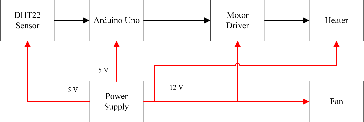
Figure 1. Block diagram system
Based on Figure 1, the red arrows signify the power connectivity to each component. The DHT22 sensor and Arduino Uno were configured to use a 5V power supply, whereas the motor driver, heater, and fan operated on a 12V configuration.
Figure 2 illustrates the block diagram of the control system. The set point value adjustments align with the desired configuration, leveraging the DHT22 sensor to measure air temperature feedback. The PID control computes the control signal value to regulate the heater, ensuring it reaches the designated level. The PID control system continuously modifies the process or system output to correspond with the specified setpoint by operating via feedback. With three actions Proportional (P), Integral (I), and Derivative (D)—the PID controller can generate a highly stable and precise response. Figure 3 provides a visual representation of the intricate hardware components used in the course of this research, providing a comprehensive overview of the technical setup used in the study.

Figure 2. Diagram block control system


Figure 3. Hardware illustration
Based on Figure 3, the devices configuration centers around a 30 cm Paralon tube that houses the essential components: a DC fan, a heater, and a DHT22 temperature sensor. Inside the tube, the fan is located at one end, while the DHT22 sensor is located at the opposite end. The heater is centrally located within the tool. Operating dynamics include active engagement of the fan, which drives airflow toward the DHT22 sensor. At the same time, the heater generates heat according to predetermined PID settings.
- Wiring Diagram System
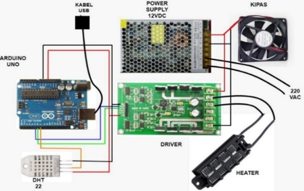
The wiring diagram is the essential element in the realization of the system's advanced air temperature control. This system organizes the capabilities of various components that are intricately woven together to facilitate seamless communication and interaction. At its core is the Arduino Uno 328P microcontroller, which acts as the brain center of the setup. The ensemble includes the L298 driver, heater, DHT22, fan and power supply. In particular, the PID control algorithm is seamlessly integrated into the Arduino's operating environment, enhancing its control capabilities.
The Arduino Uno 328P assumes the role of the critical control node, expertly interfacing with the components to capture real-time data critical to effective control strategies. Figure 4 illustrates the schematic system, providing a visual representation of the interconnected components and their functional relationships within the system.
Based on Figure 4, the wiring diagram of the air temperature control system is presented. Following hardware design, the subsequent stage creates a wiring diagram to connect all components via wires or a PCB board. It is necessary to link all constituents to the Arduino Uno microcontroller and power source using a 12V power supply. Table 1 show the details connection.

Figure 4. Wiring diagram system (Kipas, means fan, kabel USB means USB cable)
Table 1. Wiring connectivity
Components | Connectivity |
Sensor DHT22 | VCC, GND, pin 7 |
Heater | + (motor 2), - (motor2) |
Fan | Power (12V), GND |
Driver Motor 15A | VCC, GND, Dir2 (6), PWM2 (5) |
Power supply | 12V, GND |
- Flowchart System
Figure 5 illustrates the flowchart and provides a complete operational overview of the air temperature control system. This system uses a PID controller, which ensures precise regulation and control.
As shown in Figure 5, the PID control system generates control signals that enable precise temperature control. Initially, the setpoint is set by Pulse Width Modulation (PWM), driven by the DHT22 sensor readings. To achieve optimum performance, the Proportional parameter ( ), Integral parameter (
 ), and Derivative parameter (
 ) values are fine-tuned through iterative trials and adjustments.
When the PWM value is set via the DHT22 sensor, the heater activation is adjusted accordingly, resulting in the desired temperature in degrees Celsius. Determining the error values for each parameter involves calculating the discrepancy between the setpoint and the sensor temperature reading. The resulting PWM value includes the initial PWM setting and the output derived from the PID calculation.
The heater is then activated based on the PWM modulation controlled by the PID controller. The resulting temperature measured by the sensor becomes the Present Value (PV) for comparison to the Setpoint. The system seeks equilibrium by matching the PV to the setpoint. If a match occurs, the system stabilizes; however, if a mismatch persists, the system converges to the setpoint, continuously recalibrating until stability is achieved. This iterative loop ensures precision in achieving and maintaining the desired temperature setpoint.
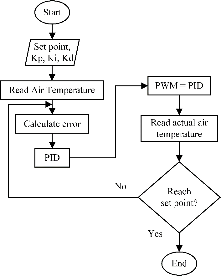
Figure 5. Flowchart system
- RESULT AND DISCUSSION
Air temperature optimization through PID control, this study explores the implementation of PID methodology for regulating and optimizing air temperature. It comprehensively analyzes how PID control impacts and optimizes air temperature within controlled environments. This study systematically evaluates the effectiveness of PID parameters in achieving rapid responses and maintaining precise air temperature outcomes. An extensive examination of PID parameters and their influence on the effectiveness of the air temperature control system is the focal point of this research project.
- Experimental of Temperature meter and data sensor DHT22 and Calibration
Figure 6 displays the PID control implementation in the hardware system's air temperature control system, which has completed the wiring configuration procedure. The circuit underwent a wiring configuration process and included several key components like a DHT22 temperature sensor, a digital thermometer, a heater, a DC fan, a 15A motor driver, an Arduino Uno microcontroller, a breadboard, and a 12V adapter.
The DHT22 temperature sensor is a vital feedback unit recording temperature data in digital signal format. When turning on the heater, it produces heat according to a predefined set value. Simultaneously, the DC fan circulates the heat throughout the room. Afterward, the DHT22 sensor measures the resulting temperature, and the program running on the Arduino Uno analyzes the data.
Commands are then sent by the program to the 15A motor driver to adjust the heater's heat output to match the targeted setpoint value. Within this research context, the DHT22 temperature sensor is the primary tool for monitoring the heater's heat output, providing real-time readings accessible through the Arduino Uno's serial monitor. The 15A motor driver is a temperature controller, precisely regulating the heater's output to match the specified setpoint value. As a result, this integrated system works in harmony to ensure comprehensive air temperature control in line with the specified parameters. Table 2 shows the experimental reading of sensor and actuator using PWM.
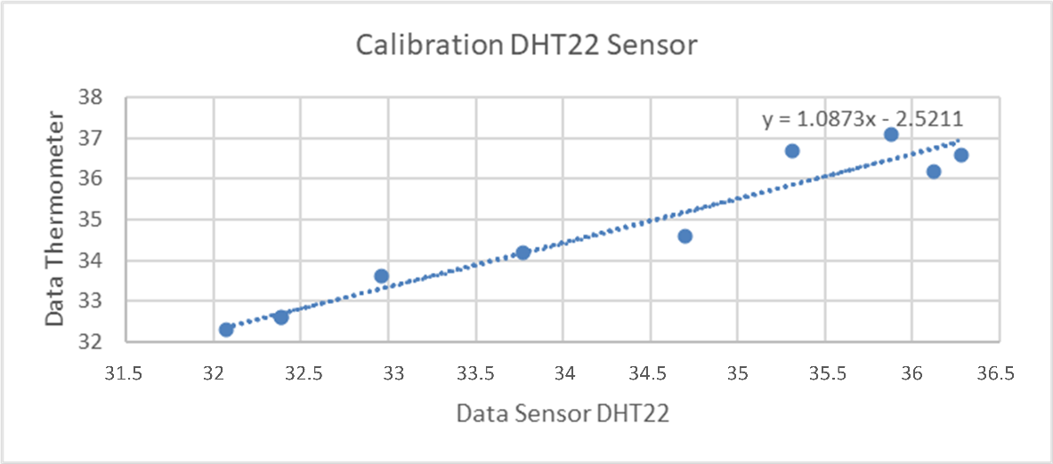
Figure 6. Device of Air Temperature Control System
Table 2. Experimental sensor and actuator
PWM | Voltage (volt) | Sensor DHT22 (°C) | Thermometer Digital(°C) | Error value |
25 | 1.11 V | 32.07 | 32.3 | 0.2°C |
50 | 2.19 V | 32.39 | 32.6 | 0.2°C |
75 | 3.27 V | 32.39 | 32.6 | 0.2°C |
100 | 4.36 V | 32.96 | 33.6 | 0.6°C |
125 | 5.47 V | 33.77 | 34.2 | 1.5°C |
150 | 6.6 V | 34.7 | 34.6 | 0.1°C |
175 | 7.72 V | 35.31 | 36.7 | 1.3°C |
200 | 8.86 V | 35.88 | 37.1 | 1.2°C |
225 | 10.04 V | 36.1 | 36.2 | 0.1°C |
250 | 11.12 V | 36.3 | 36.6 | 0.3°C |
Table 2 displays data obtained from experiments on the air temperature control system using Pulse Width Modulation (PWM) values and their effects on voltage, DHT22 sensor readings, and digital thermometer measurements. Abbreviations are explained upon first use. A linear relationship exists between the PWM settings and resultant voltage output, with increasing PWM values leading to higher voltage levels.
Intriguing observations arise upon analysis of temperature readings from the DHT22 sensor and digital thermometer. At lower PWM values ranging from 25 to 100, recorded temperatures show a consistent pattern, maintaining proximity between the DHT22 sensor and digital thermometer readings. Error-values ranging from 0.2 to 0.6 degrees Celsius were observed. As PWM values increase beyond 100, a significant difference arises between the sensor readings and digital thermometer measurements. This discrepancy becomes more noticeable, with error values ranging from 0.1 to 1.5 degrees Celsius.
Therefore, it suggests a potential non-linear relationship between PWM, voltage output, and actual temperature regulation at higher PWM values. Further investigation may be necessary to address these disparities. These results could involve recalibration or adjustments to the PID control parameters for improved temperature control at high PWM settings. These findings emphasize the importance of comprehending the intricate relationship between PWM modulation, voltage, and temperature outcomes when optimizing air temperature regulation through PID control systems. Figure 7 shows the calibration of DHT22 sensor using linear regression.
Based on the calibration in Figure 7, we employed a Linear Regression model to calibrate the data. The resulting equation,  , defines '
 ' as the dependent variable and '
 ' as the independent variable, where '
 ' represents the DHT22 data. This regression analysis aims to establish a functional relationship between the variables, enabling the estimation or prediction of one variable based on the other. Calibration processes are essential for interpreting and utilizing data to improve the precision and dependability of measurements or predictions within experimental settings.
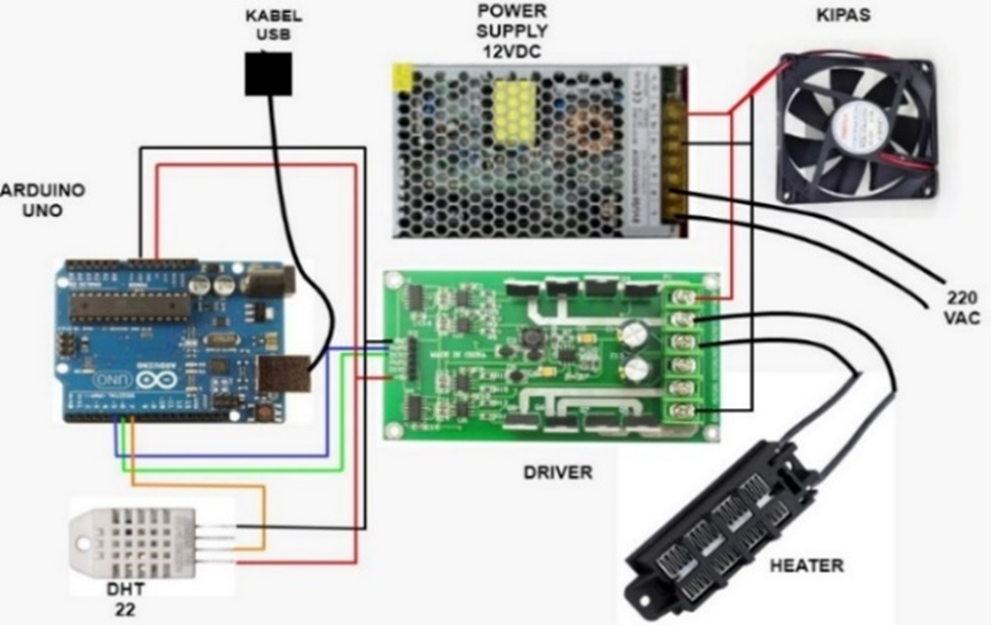
Figure 7. Calibration DHT22 Sensor
- Proportional (P) Controller
Throughout the experimental trials, the proportional control system adjusted its  values, set at 5, 10, 15, 20, and 25, while keeping the
  and
and  values parameter at 0. The main aim of this deliberate variation in the
  parameter was to objectively analyze the system's graphical response across different parameter values. The results presenting the outcomes of system testing for other proportional parameters are presented and explained in Table 3.
Table 3. Response analysis Proportional Controller

| Rise Time (TR) | Overshoot (MP) | Peak Time (TS) | Settling Time (TS) | Steady State Error |
5 | NaN | 0 | 98 | NaN | 3.0200 |
10 | NaN | 0 | 138 | NaN | 2.9300 |
15 | NaN | 0 | 932 | NaN | 2.7700 |
20 | NaN | 0 | 242 | NaN | 2.7700 |
25 | NaN | 0 | 402 | NaN | 2.5300 |
Table 3 displays the gathered data from the stepinfo function in MATLAB, which functions as a tool for analyzing the response dynamics of the PID control system with different  values. The preliminary testing, wherein
  was set to 5,
  to 0, and
  to 0, showed the following response parameters: NaN rise time, 0 overshoot, a peak time of 98, NaN settling time, and a steady-state error of 3.0200. The subsequent experiments involved increasing the
  value in 10, 15, 20, and 25 increments while keeping
  and
and  at a parameter of 0. Critical system characteristics were recorded during each test, including rise time, overshoot, peak time, settling time, and steady-state error. These findings demonstrate the discernable impact of the
  value on the system's response. Increasing
  values can move the system toward the target set point but can also trigger system instability, heightened oscillations, increased overshoot, and reduced steady-state error.
The acronym NaN, seen in the test results, means "Not a Number," indicating an uncertain or invalid value within floating-point arithmetic. The graph illustrates how the system responds to changes in  values. Analyzing this visual output is crucial for interpreting how the system reacts to varying
  ratios, allowing for the identification of the best
  value for precise temperature control. Figure 8 shows the temperature response using Proportional Controller.
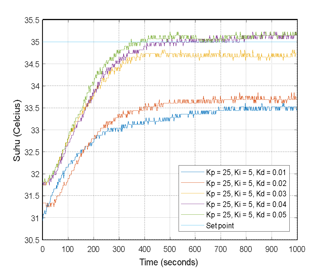
Figure 8. Temperature response with Proportional Controller
- Proportional Integral (PI) Controller
In the previous experiments, the Proportional-Integral (PI) control system faced challenges in reaching a steady-state value, primarily due to an unknown settling time. To enhance system stability, we introduced derivative control in this experiment to refine the response characteristics and achieve more excellent output stability.
During the testing phase, the system's  and
and  values were predetermined at 25 and 5, respectively, based on optimal settings from previous trials involving the proportional-integral control system.
  =0.01,
  =0.02,
  =0.03,
  =0.04, and
  =0.05. Next, we systematically varied the derivative value (
 ) to explore the system's response under different derivative control values. This deliberate alteration was intended to analyze and investigate the system's performance. The comprehensive results of the proportional-integral-derivative (PID) control system trial are meticulously outlined and shown in Table 4 for thorough examination and evaluation.
Table 4. Response analysis Proportional Integral Controller

| 
| Rise Time (TR) | Overshoot (MP) | Peak Time (TS) | Settling Time (TS) | Steady State Error |
25 | 1 | NaN | 0 | 774 | NaN | 0.8200 |
25 | 2 | 939.2000 | 0 | 992 | NaN | 0.5000 |
25 | 3 | 424.2000 | 0 | 658 | NaN | 0.2600 |
25 | 4 | 345.4250 | 0 | 784 | NaN | 0.1800 |
25 | 5 | 293.8250 | 0.6571 | 928 | 996.2400 | 0.0100 |
Table 4 presents the results of the temperature control system trial that utilized the combined proportional and integral (PI) control, with  = 25 and
  = 0. We varied
  values between 1 and 5 throughout various trials, while Kd remained parameter at 0. These trials facilitated the capture and analysis of multiple parameters that impact the system's efficacy and behavior.
In the first trial involving  = 1, significant outcomes were observed, demonstrating a system response with an immeasurable rise and settling time (NaN). Furthermore, the result showed a stable-state error of 0.8200. Follow-up trials revealed the influence of gradual increases in
  values on the system. When
  was set to 2, a significant rise in time to 939.2000 was achieved, but it was accompanied by a decrease in the steady-state error to 0.5000. With higher
  values, the system's response dynamics became more evident. For instance, during the third trial, a significant decrease in rise time to 424.2000 coincided with a further reduction in steady-state error to 0.2600.
In the fourth trial, with  set to 4, both rise time and steady-state error declined to 345.4250 and 0.1800, respectively. During the fifth trial, employing the highest
  value of 5, an increase in overshoot (0.6571) was observed alongside an extended rise time of 293.8250; however, it resulted in the lowest steady-state error of 0.0100. The undefined values in rise time and settling time highlight the system's difficulty in achieving stability under specific testing conditions. Furthermore, Figure 9 illustrates the system's response trend as
  values increase.
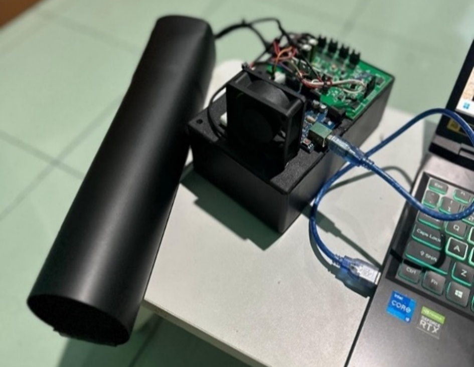
Figure 9. Temperature response with Proportional Integral Controller
- Proportional Integral Derivative (PID) Controller
In the previous experiments, the proportional-integral (PI) control system faced hurdles in reaching a stable state, as evidenced by an unknown settling time. The subsequent experiment introduced derivative control to improve the system's stability. The goal was to enhance the system's response characteristics and address the previous challenge.
Throughout testing, the system was conFigured with predetermined  =25 and
  =5 values derived from optimal settings established in previous trials of proportional-integral control systems. Subsequently, the derivative value (
 ) underwent systematic variation, set explicitly at
  =0.01,
  =0.02,
  =0.03,
  =0.04, and
  =0.05, to scrutinize and comprehend the system's response across diverse derivative control values. The comprehensive outcomes derived from the proportional-integral-derivative (PID) control system's testing are meticulously detailed and presented in Table 5, providing a comprehensive overview for analysis and interpretation.
Table 5. Response analysis PID Controller

| 
| 
| Rise Time (TR) | Overshoot (MP) | Peak Time (TS) | Settling Time (TS) | Steady State Error |
15 | 5 | 0.01 | NaN | 0 | 796 | NaN | 1.560 |
15 | 5 | 0.02 | NaN | 0 | 774 | NaN | 1.310 |
15 | 5 | 0.03 | 329.2639 | 0 | 470 | NaN | 0.260 |
15 | 5 | 0.04 | 257.5750 | 0.6571 | 826 | NaN | -0.150 |
15 | 5 | 0.05 | 229.5750 | 0.6571 | 500 | NaN | -0.150 |
Table 5 summarizes the results of several tests conducted on a proportional-integral-derivative (PID) control system. The study focused on varying  values while keeping
  =15 and
  =5 and aimed to explore the effect of changes in the Kd parameter, which is essential in determining the system's behavior.
Beginning with the first test using  = 0.01, the recorded response shows an unmeasurable rise time (NaN), zero observed overshoot, a peak time of 796, an undetermined settling time (NaN), and a steady-state error of 1.5600. Tests following with
  = 0.02 demonstrated similar results, with comparable rise time and overshoot characteristics.
The results of the third trial indicate that a Kd value of 0.03 resulted in a rise time of about 329.2639, zero overshoot, a peak time of 470, an indeterminate settling time (NaN), and a decreased steady-state error of 0.2600. The fourth and fifth experiments used  values of 0.04 and 0.05, respectively, demonstrating higher overshoot and quicker rise times while maintaining an indeterminate settling time.
These experiments shed light on the system's sensitivity to derivative control ( ) despite the inconclusive settling times (NaN). The rise time, overshoot, and peak time parameters varied with changes to
  . Notably, the sustained low steady-state error indicates the efficacy of derivative control in improving the system's accuracy in reaching the target setpoint.
Figure 10 accompanies this text and displays the system's response to a range of  values. The tests thoroughly understand how derivative control affects a PID control system's response. Identifying the ideal
  value requires a comprehensive assessment of the system's demands and characteristics. These test results present valuable insights into the intricate impacts of derivative control on system behavior.
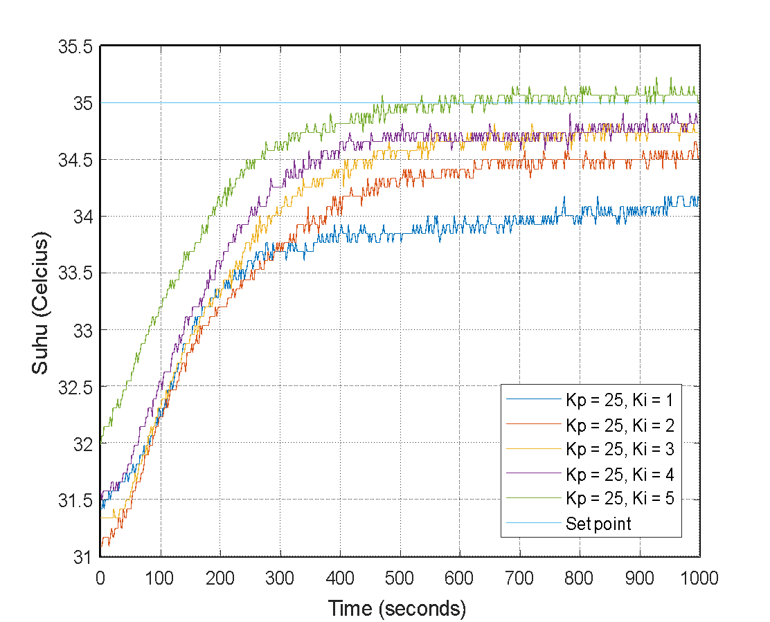
Figure 10. Temperature Response PID Controller
- Best Parameter Proportional Integral Controller (PID) Controller
The parameter tuning procedure yielded the optimal PID parameters for optimizing the temperature control system.  = 14.6,
  = 0.376, and
  = 8 were the most appropriate. Table 6 shows the tuning response results for three separate setpoints, 34, 35, and 36. The system exhibited an optimal performance profile at these points, with minimal overshoot, fast rise time, and negligible settling time, and details the response results obtained by implementing the best PID parameters at these three set points, giving a thorough picture of the system's performance at different temperature set points.
Table 6. Response analysis the best parameter PID Controller

| 
| 
| Rise Time (TR) | Overshoot (MP) | Peak Time (TS) | Settling Time (TS) | Steady State Error |
14.6 | 0.376 | 8 | 142 | 0.8824 | 994.36 | 0.1 | 34 |
14.6 | 0.376 | 8 | 339.6 | 0.8571 | 993.92 | 0 | 35 |
14.6 | 0.376 | 8 | 348.8 | 0.5556 | 992.84 | 0.1 | 36 |
Based on the tuning results of the PID parameters shown in Table 6, the system's response displays notable performance enhancement compared to its previous configuration. The optimal PID parameters ( = 14.6,
  = 0.376, and
  = 8) provide the finest results in the test with set point 34, with an overshoot of less than 1% and a rise time of roughly 142 seconds. Although there is an increase in rise time to 339.6 seconds and 348.8 seconds at set points 35 and 36, respectively, this can be attributed to the 50-watt heating power limitation and system efficiency, affecting the response time.
All systems with these best parameters exhibited optimal settling times ranging from 992.82 to 994.36 seconds. This finding indicates that the system can quickly and stably reach the set point value without significant oscillations. Furthermore, the system demonstrates high accuracy in achieving and maintaining the temperature at the specified set point, as evidenced by the steady-state error in each test approaching zero.
A graph in Figure 11 illustrates the best PID parameter test results, conducted at three different set points and aligned with the data presented in the Table 6. The chart indicates a consistent response, meeting the intended objective by verifying the effective system performance enhancement through PID tuning. Therefore, implementing the optimized PID configuration effectively sustains desired temperature levels in the given environment.
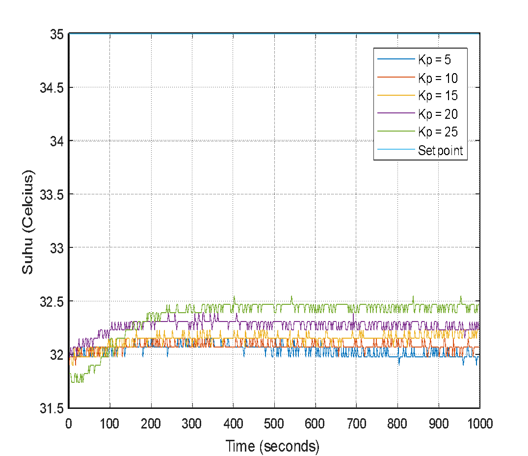
Figure 11. Temperature response the best PID with varying set point
- CONCLUSIONS
The research "Implementing PID Control on Arduino Uno for Air Temperature Optimization" actively engaged in designing, constructing, and rigorously testing a system to attain precise temperature regulation, yielding invaluable insights. Firstly, the study rigorously tested and verified system components, explicitly scrutinizing the DHT22 temperature sensor and assessing PWM voltage at the heater's output. This emphasized the pivotal role of component scrutiny in upholding system precision and consistency. Additionally, the research employed linear regression to calibrate the DHT22 sensor, enhancing its accuracy to align readings with thermometer data and ensure a reliable temperature representation. Furthermore, this study identified the most effective configuration for precise air temperature control via optimal PID controller parameters:  = 14.6,
  = 0.376, and
  = 8. Under these parameters, the system showcased swift response times, particularly demonstrating rapid responses below 35°C in about 142 seconds. Temperatures at 35°C and 36°C exhibited similar response times, approximately 339.6 and 348.8 seconds, respectively. With an overshoot of less than 1%, the system achieved stability within roughly 990 seconds. This investigation underscores the efficacy of PID controllers in attaining precise air temperature regulation, emphasizing the critical role of meticulous parameter tuning for practical implementation in temperature regulation systems. The integration of evolutionary optimization methods, such as Genetic Algorithm and Particle Swarm Optimization, with PID has the potential to improve this research. This approach is expected to facilitate the critical component of dynamic system control, the PID parameter tuning process. The effectiveness of PID parameter tuning can be strengthened by exploring the solution space holistically through the integration of evolutionary optimization methods, such as Genetic Algorithms. Similarly, the application of the Particle Swarm Optimization method is expected to improve convergence capability and precision in determining the optimal PID parameters. Combining the evolutionary optimization algorithm with PID has the potential to achieve an optimal balance between exploration and exploitation in finding optimal solutions for dynamic control systems. Therefore, this approach is expected to improve the overall performance of the control system.
REFERENCES
- T. Susanto, M. Bayu Setiawan, A. Jayadi, F. Rossi, A. Hamdhi and J. Persada Sembiring, "Application of Unmanned Aircraft PID Control System for Roll, Pitch and Yaw Stability on Fixed Wings," 2021 International Conference on Computer Science, Information Technology, and Electrical Engineering (ICOMITEE), pp. 186-190, 2021, https://doi.org/10.1109/ICOMITEE53461.2021.9650314.
- J. Kim, S. Kim, C. Ju and H. I. Son, "Unmanned Aerial Vehicles in Agriculture: A Review of Perspective of Platform, Control, and Applications," in IEEE Access, vol. 7, pp. 105100-105115, 2019, doi: https://doi.org/10.1109/ACCESS.2019.2932119.
- P. K. Chittoor, B. Chokkalingam and L. Mihet-Popa, "A Review on UAV Wireless Charging: Fundamentals, Applications, Charging Techniques and Standards," in IEEE Access, vol. 9, pp. 69235-69266, 2021, doi: https://doi.org/10.1109/ACCESS.2021.3077041.
- S. Wilson et al., "The Robotarium: Globally Impactful Opportunities, Challenges, and Lessons Learned in Remote-Access, Distributed Control of Multirobot Systems," in IEEE Control Systems Magazine, vol. 40, no. 1, pp. 26-44, 2020, https://doi.org/10.1109/MCS.2019.2949973.
- A. Stefek, T. V. Pham, V. Krivanek and K. L. Pham, "Energy Comparison of Controllers Used for a Differential Drive Wheeled Mobile Robot," in IEEE Access, vol. 8, pp. 170915-170927, 2020, doi: https://doi.org/10.1109/ACCESS.2020.3023345.
- Z. Liu, A. Mohammadzadeh, H. Turabieh, M. Mafarja, S. S. Band and A. Mosavi, "A New Online Learned Interval Type-3 Fuzzy Control System for Solar Energy Management Systems," in IEEE Access, vol. 9, pp. 10498-10508, 2021, https://doi.org/10.1109/ACCESS.2021.3049301.
- M. Danita, B. Mathew, N. Shereen, N. Sharon and J. J. Paul, "IoT Based Automated Greenhouse Monitoring System," 2018 Second International Conference on Intelligent Computing and Control Systems (ICICCS), pp. 1933-1937, 2018, https://doi.org/10.1109/ICCONS.2018.8662911.
- H. Shareef, M. S. Ahmed, A. Mohamed and E. Al Hassan, "Review on Home Energy Management System Considering Demand Responses, Smart Technologies, and Intelligent Controllers," in IEEE Access, vol. 6, pp. 24498-24509, 2018, https://doi.org/10.1109/ACCESS.2018.2831917.
- H. Zhang, D. Wu and B. Boulet, "A Review of Recent Advances on Reinforcement Learning for Smart Home Energy Management," 2020 IEEE Electric Power and Energy Conference (EPEC), 2020, pp. 1-6, doi: https://doi.org/10.1109/EPEC48502.2020.9320042.
- M. Chen, D. Zhou and F. Blaabjerg, "Enhanced Transient Angle Stability Control of Grid-Forming Converter Based on Virtual Synchronous Generator," in IEEE Transactions on Industrial Electronics, vol. 69, no. 9, pp. 9133-9144, 2022, https://doi.org/10.1109/TIE.2021.3114723.
- S. Badnava et al., "Platoon Transitional Maneuver Control System: A Review," in IEEE Access, vol. 9, pp. 88327-88347, 2021, doi: https://doi.org/10.1109/ACCESS.2021.3089615.
- S. K. Sunori, A. S. Bhakuni, S. Maurya, G. S. Jethi and P. K. Juneja, "Improving the Performance of Control System for Headbox Consistency of Paper Mill Using Simulated Annealing," 2020 Fourth International Conference on I-SMAC (IoT in Social, Mobile, Analytics and Cloud) (I-SMAC), pp. 1111-1116, 2020, https://doi.org/10.1109/I-SMAC49090.2020.9243567.
- T. Inovan, A. I. Cahyadi and O. Wahyunggoro, "Implementation of Adaptive-PID Based Temperature Trajectory Tracking Control to Improve Repeatability in Coffee Roasting," 2023 IEEE International Conference on Industry 4.0, Artificial Intelligence, and Communications Technology (IAICT), pp. 162-167, 2023, https://doi.org/10.1109/IAICT59002.2023.10205885.
- T. Jia, K. Yang, Z. Peng, L. Tang, H. Duan and Y. Luo, "Review on the Change Trend, Attribution Analysis, Retrieval, Simulation, and Prediction of Lake Surface Water Temperature," in IEEE Journal of Selected Topics in Applied Earth Observations and Remote Sensing, vol. 15, pp. 6324-6355, 2022, https://doi.org/10.1109/JSTARS.2022.3188788.
- J. Moreno-Valenzuela, R. Pérez-Alcocer, M. Guerrero-Medina and A. Dzul, "Nonlinear PID-Type Controller for Quadrotor Trajectory Tracking," in IEEE/ASME Transactions on Mechatronics, vol. 23, no. 5, pp. 2436-2447, 2018, https://doi.org/10.1109/TMECH.2018.2855161.
- M. Mahmud, S. M. A. Motakabber, A. H. M. Zahirul Alam and A. N. Nordin, "Adaptive PID Controller Using for Speed Control of the BLDC Motor," 2020 IEEE International Conference on Semiconductor Electronics (ICSE), pp. 168-171, 2020, https://doi.org/10.1109/ICSE49846.2020.9166883.
- B. Verma and P. K. Padhy, "Robust Fine Tuning of Optimal PID Controller With Guaranteed Robustness," in IEEE Transactions on Industrial Electronics, vol. 67, no. 6, pp. 4911-4920, 2020, https://doi.org/10.1109/TIE.2019.2924603.
- K. Nouman, Z. Asim and K. Qasim, "Comprehensive Study on Performance of PID Controller and its Applications," 2018 2nd IEEE Advanced Information Management,Communicates,Electronic and Automation Control Conference (IMCEC), pp. 1574-1579, 2018, https://doi.org/10.1109/IMCEC.2018.8469267.
- H. Geng, Z. Zheng, T. Zou, B. Chu and A. Chandra, "Fast Repetitive Control With Harmonic Correction Loops for Shunt Active Power Filter Applied in Weak Grid," in IEEE Transactions on Industry Applications, vol. 55, no. 3, pp. 3198-3206, 2019, https://doi.org/10.1109/TIA.2019.2895570.
- A. Altayeva, B. Omarov and Y. I. Cho, "Towards Smart City Platform Intelligence: PI Decoupling Math Model for Temperature and Humidity Control," 2018 IEEE International Conference on Big Data and Smart Computing (BigComp), pp. 693-696, 2018, https://doi.org/10.1109/BigComp.2018.00128.
- E. Merzlikina, H. Van Va and G. Farafonov, "Automatic Control System with an Autotuning Module and a Predictive PID-Algorithm for Thermal Processes," 2021 International Conference on Industrial Engineering, Applications and Manufacturing (ICIEAM), pp. 525-529, 2021, https://doi.org/10.1109/ICIEAM51226.2021.9446467.
- J. P. Mandap, D. Sze, G. N. Reyes, S. Matthew Dumlao, R. Reyes and W. Y. Danny Chung, "Aquaponics pH Level, Temperature, and Dissolved Oxygen Monitoring and Control System Using Raspberry Pi as Network Backbone," TENCON 2018 - 2018 IEEE Region 10 Conference, pp. 1381-1386, 2018, https://doi.org/10.1109/TENCON.2018.8650469.
- A. Punse, S. Nangrani and R. Jain, "A Novel Application of Multipoint Temperature Control Using PID," 2019 3rd International Conference on Computing Methodologies and Communication (ICCMC), pp. 1191-1196, 2019, https://doi.org/10.1109/ICCMC.2019.8819722.
- N. E. -T. Tochukwu, A. K. Tetteh and G. K. Agordzo, "Investigation on the Temperature Stabilization of the Laser Diode Based on PID Control," 2022 IEEE Delhi Section Conference (DELCON), pp. 1-8, 2022, https://doi.org/10.1109/DELCON54057.2022.9752826.
- E. Alexis, L. Cardelli and A. Papachristodoulou, "On the Design of a PID Bio-Controller With Set Point Weighting and Filtered Derivative Action," in IEEE Control Systems Letters, vol. 6, pp. 3134-3139, 2022, https://doi.org/10.1109/LCSYS.2022.3182911.
- A. A. Cahya and R. D. Puriyanto, “The Design of Rice Milling and Screening Systems Uses the DC Motor PID Method,” Control Systems and Optimization Letters, vol. 1, no. 1, pp. 1–6, 2023, https://doi.org/10.59247/csol.v1i1.2.
- O. Arrieta, D. Castillo, R. Vilanova, and J. D. Rojas, “Model Reference based tuning for fractional-order 2DoF PI controllers with a robustness consideration,” IFAC-PapersOnLine, vol. 52, no. 1, pp. 207-212, 2019, https://doi.org/10.1016/j.ifacol.2019.06.063.
- Y. Pan, X. Li and H. Yu, "Efficient PID Tracking Control of Robotic Manipulators Driven by Compliant Actuators," in IEEE Transactions on Control Systems Technology, vol. 27, no. 2, pp. 915-922, 2019, https://doi.org/10.1109/TCST.2017.2783339.
- J. Li and W. Li, "On-Line PID Parameters Optimization Control for Wind Power Generation System Based on Genetic Algorithm," in IEEE Access, vol. 8, pp. 137094-137100, 2020, https://doi.org/10.1109/ACCESS.2020.3009240.
- S. Wang and F. He, "Control technology and strategy of tension control system," 2018 Chinese Control And Decision Conference (CCDC), pp. 2620-2625, 2018, https://doi.org/10.1109/CCDC.2018.8407568.
Implementing PID Control on Arduino Uno for Air Temperature Optimization (Afindra Hafiedz Akbar)