Buletin Ilmiah Sarjana Teknik Elektro ISSN: 2685-9572
Bond Graph Dynamic Modeling of Wind Turbine with Singly-feed Induction Generator
Sugiarto Kadiman, Oni Yuliani, Diah Suwarti
Department of Electrical Engineering, Institut Teknologi Nasional Yogyakarta, Indonesia
ARTICLE INFORMATION |
| ABSTRACT |
Article History: Received 22 November 2023 Revised 30 March 2024 Published 19 January 2025 |
| 
This paper contributes to a modeling part of singly-fed induction generator (SFIG) systems driven by constant wind turbines of generation capacity of 2.5 kW. As a consequence of some physical domains present in wind turbine, that are aerodynamical, mechanical and electrical, the modeling of wind turbine is challenging; therefore, modeling based on physical techniques has a higher credibility in these conditions. One of these ways is Bond-Graph modeling those representations the systems developed from the law of conservation of mass and energy covering in the systems. Bond graph uses causal analysis which is a process for identifying and addressing the causes and effects of a problem; moreover, the model is presented visually so that they are easier and more user friendly. In this paper, modeling the parts of among blades, tower, gearbox, and induction generator are based on the bond-graph method. The blades are modeled based on aerodynamic force model, both tower and gearbox are modeled based on rigid components model, and generator is model based on hybrid mechanic-electric model. Then, all of parts are connected together to accomplish the entire model of wind turbine for simulation based on 20-Sim software. The proposed wind turbine is the 2.5 KW variable speed with three blades, two-mass gearbox, tower, and a singly-fed induction generator type which is used in small and isolated category power generation systems. The model consists of realistic parameters. Using the Bond-Graph modeling method makes it easier to know what is actually happening in the system, for example the direction of energy movement in the system. Simulation results point out better performance of wind turbine with singly-feed induction generator, namely a more constant output current under constant wind conditions compared to varying wind conditions. |
Keywords: Singly-fed Induction Generator; Physical Domains; Bond-Graph; Constant and Variable Speeds; 20-Sim Software |
Corresponding Author: Sugiarto Kadiman, Department of Electrical Engineering, Institut Teknologi Nasional Yogyakarta, Yogyakarta, Indonesia. Email: sugiarto.kadiman@itny.ac.id |
This work is licensed under a Creative Commons Attribution-Share Alike 4.0 
|
Document Citation: S. Kadiman, O. Yuliani, and D. Suwarti, “Bond Graph Dynamic Modeling of Wind Turbine with Singly-feed Induction Generator,” Buletin Ilmiah Sarjana Teknik Elektro, vol. 6, no. 4, pp. 381-391, 2024, DOI: 10.12928/biste.v6i4.9409. |
- INTRODUCTION
Wind turbine is a multi-domain and complicated system that numerous methodical areas are implied, such as aerodynamic, mechanical, and electrical. Latterly some publications deal with this matter. Renewable energy sources are the most attractive substitutions to declining the after-effects of climate issues. Throughout clean energy, wind energy has the quickest and most relevant evolution [1]-[5]. Wind energy is the second foremost favorite of renewable energy for electricity generation after hydro power caused by its relatively simple substructure, cost-usefulness, and maturity of technology. A massive portion of the established explanations is recognized over typical of wind turbine constructions. Their typical structures become an important attraction a part of the discourse.
Stand-alone wind turbines propose an attracting renewable energy source for isolated or remote areas. These wind turbines reduce the pollution, decreasing the need for diesel generators which burn up a lot of polluting fuel; and it can be allocated wherever wind resource is acceptable and there is no get into to the grid [6]. The recent researches in wind turbine are debating the idea of using induction generator in stand alone small wind turbine as a consequence their advantages over synchronous generators, such as smaller size, lower cost, and lesser maintenance [7]-[8].
Throughout number of years, it was a number of discourses involving modelling of wind turbine accurately. Many scholars carry out studies on the dynamic analysis of model wind turbine using one-mass and two-mass models [9][10]. Generally, the abridged two-mass model is the most utilized in the literature to signify the forces applied to the transmission drive train of the wind turbine. These studies exposes the importance of having an accurate model of the wind turbine, as a way to dynamic studies of a system. Being a self complexity, it looks to using a general method for modeling the whole of wind turbine.
Under this context, for the purpose of analyzing the system in the equal reference frame, the Bond-Graph methodology can embody the whole structure. This methodology offers some correctness that can be functional at once to the model. A Bond-Graph comprises of sub-systems coupled together by power bonds. They exchange instantaneous power at ports. The variables that are forced to be the same, when two ports are linked are the power variables, counted as functions of time. The important gains of the Bond-Graph tool for modeling purposes are a unified graphical language aims to depict with physical perception power interactions, energy dissipation and storage phenomena in dynamic systems of each physical domain and also the visualization instrument of causality properties for writing equations equivalent to chosen modeling guesses. More information can be found in [11].
The model of Bond-Graph based wind turbine can be acquired in various studies [12]-[16]. A comprehensive model of a blade is suggested in the first. The aerodynamic forces are regarded, and for the purpose of evaluating the output power and blade characteristic, real data of a wind turbine are applied. Also, it is a general model that can be applied to each wind turbine blade. In [17], an accomplish wind turbine based on parameters taken from a real turbine is proposed. The model expresses whole components of the wind turbine, nonetheless the aerodynamics are not reviewed in feature. The study is concentrating on monitoring the wind turbine geared systems beneath hybrid unpredictability.
Many wind turbines employ an induction machine to work as generator [18]-[21]. The induction machine, namely a squirrel cage induction machine or singly-fed induction generator is applied as an aim to permit an easy connecting to the external power network. The singly-fed induction generators used in smaller systems are unmatched relating to cost and low maintenance and do not necessitate a complex blade pitch control procedure. Small singly-fed induction generators have relatively high nominal slip values which deliver adequate compliance to the grid. And its comportments the wind turbine without the power electronics converters requirement in other arrangements.
In this study a model of Bond-Graph based wind turbine has three blades, gearbox, tower, and singly-fed induction generator 2.5 kW. The framework of this study is as follows: first, the wind turbine model is developed. Then, the comprehensive model is simulated based on 20-Sim software [22]. Following section defines result and analysis. Finally, conclusions of the study are presented.
- METHODS
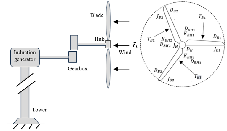
Figure 1 shows a portrayal of a wind turbine [23]. It includes of six inertias which are the three blades, hub, gearbox and a SFIG. The inputs are wind speed and electromagnetic torque. To accomplish the dynamic equations for this wind turbine model applying Newton’s second law can be fairly difficult, and some faults can be easily made. This is why the differential equations are added for the simplified case. Figure 2 illustrations a simplified wind turbine model using a three-mass diagram of wind turbine, where  and
and  denote generator inertia, hub inertia, electro-magnetic torque, and aerodynamic torque, respectively. While Figure 3 depicts mechanical diagram of wind turbine with blade, gearbox, and induction generator. All parameters are described in Table 1.

Figure 1. Wind turbine model
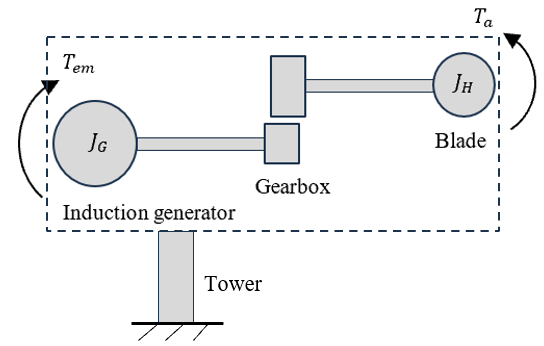
Figure 2. Simplified wind turbine model
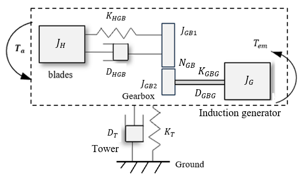
Figure 3. Mechanical diagram of wind turbine with blade, gearbox, and generator
Table 1 Abbreviations in relation with Figure 1, Figure 2, and Figure 3
Abbrev. | Information | Abbrev. | Information |

| Blade torque-1 from wind | 
| Stiffness between hub and gearbox |

| Blade torque-2 from wind | 
| Stiffness between gearbox and generator |

| Blade torque-3 from wind | 
| Damping between hub and gearbox |

| Hub intertia | 
| Damping between gearbox and generator |

| Hub damping | 
| Generator inertia |

| Gearbox-1damping | 
| Electromagnetic torque |

| Gearbox-2 damping | 
| Aerodynamic torque |

| Wind thrust |

| Gearbox-1 ratio | 
| Tower stifness |

| Tower damping |
All physical model of the blade is created on Rayleigh beam structure and blade element momentum (BEM) method [24][25]. These methods adapt the blade as stiffness frame dynamics where its sections are basically detached structure frameworks, achieved by partial differential calculation, and are massed in space by finite elements, shown in Figure 4. Every section has own displacement and this movement can be expressed as generalized Newton forces and displacements.

|
(a) | (b) | (c) |
Figure 4. (a) Blade form of wind turbine; (b) N-sections of blade; (c) Beam with force and displacement
The blade beam section based on Bond-Graph is formed by massing part inertias on center of gravity of the sections and linking it to the  characterizing movements and rotates at gravity center of the element. The blade construction is made by using
  and
and  elements. Both elements characterize the rigidity and the physical absorbing mode between gravity center of neighboring sections. The boundary form of the model is designated between
  and
and  sources. Assembly between blade and hub is assumed to be stiff, explicitly,
  . Apparently, the blade generates one degree of freedom,
  . To end, the rotating inertia
  i is the stiffness frame of a whole blade.
The rotating inertia  displays a derivative causality as rotational speed is identified with bond 1. Factually, blades generate the torque as output; its necessities the rotational speed as input. Moreover, bond 1 necessitaes a connection alongside the hub. The reduced Bond graph shape of a ductile blade is seen in Figure 5. In Figure 5, the parameters of
  ,
,  , and
, and  are wind speed, rotor revolving speed, and pitch angle, respectively.
A picture of a two-mass gearbox model is shown in Figure 6. In this study, the assumption for using a two-mass model is enough. Through using Newton’s second law on rotational procedure of the wind turbine drawing in Figure 6, it would be got up with the following equations.
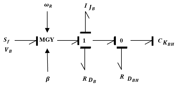
Figure 5. Turbine blade-based Bond-Graph model
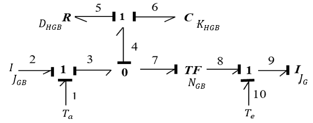
Figure 6. Bond-Graph representation of gearbox model
| 
| (1) |
As for speed difference between hub and gearbox
| 
| (2) |
While for the gearbox, it will apply
| 
| (3) |
And speed difference between gearbox and induction generator denotes
| 
| (4) |
The mechanical system can be transformed in Figure 3 into a Bond-Graph description.
It is supposed that the tower fluctuation does not effect the mechanical system, it only influences on its input, such as the wind speed [26][27]. The Bond-Graph model of the tower fluctuation can be viewed in Figure 7. The graph in Figure 8 is a cut down of Figure 7. It is assumed zero input force from the ground and each time there are get ahead of bonds on a junction that can remove them.
The Bond-Graph model embodying the mechanical system depicted in Figure 1 can be viewed in Figure 9 [26]. Later, the inputs are wind speed containing tower movement on every blade and generator torque. The wind speed is deliver for through a modulated gyrator which transforms flow into effort corresponding to a formula set in within the gyrator. This conversion is dependent on the blades pitch angle, consequently the modulated gyrator. It can be also noted that all the  ,
,  and
and  -elements comprise the same causality, respectively. Every element has their chosen causality.

| 
|
Figure 7. Bond-graph of tower fluctuation | Figure 8. Simplified of tower fluctuation |
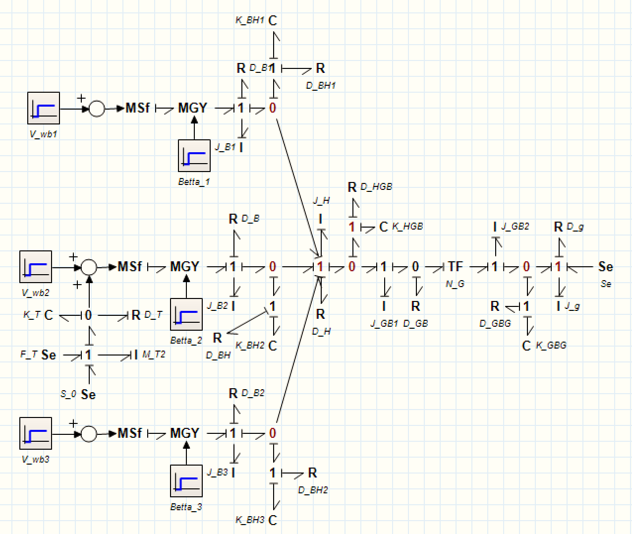
Figure 9. Bond Graph representation of wind turbine model
In a singly-fed induction generator, such as squirrel cage induction generator, the three energy ports are stator, rotor, and shaft. Stator collects its energy delivery from the mains; the rotor may also be provided with electric energy from mains as in induction generator or share the electric energy with stator as in squirrel cage. The shaft distributes mechanical energy to the joined load. The energy conversation between the three ports performs in the air gap.
The dynamic mathematical model of a singly-fed induction generator is usually a set of fifth order non-linear differential equations [29][30]. Karnopp [31] suggests a Bond-Graph model describing these equations. The hypothesis viewed for the SFIG model that the joint inductances containing armature, dampers, and field on direct axis windings are identical is the basis of standard theory of the generator model. Besides, both copper losses and machine slots are unobserved and the un-restrictedness distribution of the stator fluxes and apertures wave are sinusoidal wave forms. The damper winding that are sited next to air-gap present flux involving damper circuits whose value is around equivalent to flux linking armature.
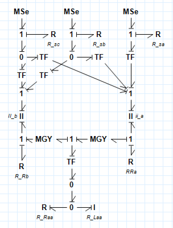
To represent real system elements decidedly, certain Bond-Graph elements should be attached. In Figure 10(a),  and
and  phase stator resistance elements,
  and
and  should be split into three stator coil resistances
  ,
,  , and
, and  , to make obvious the resistance of each stator coils. This was accomplished without altering the dominant equations which is under conventions of a spatially sinusoidal distribution of MMFs, and disregarding magnetic losses and saturation [32][33], Eq. (5) relates stator voltages to stator and rotor currents. Besides, necessary is the electro-magnetic motor torque for a P-pole machine, stated as
| 
| (5) |
Terms of Eq. (6) to Eq. (7) symbolize rotor inertial torque, shaft damping torque, and load torque, respectively. While,  and
and  describe
  and
and  axis stator voltages;
  and
and  denote
  and
and  axis stator currents;
  and
and  indicate
  and
and  axis rotor currents.
  and
and  mean stator and rotor resistances, stator self-inductance, mutual inductance, and rotor self-inductance, respectively. Then,
  and P are electro-magnetic torque, mechanical load torque, moment of inertia of the rotor, viscous resistance coefficient, electrical, mechanical angular velocities of the rotor, and number of pole pairs, repectively.
| 
| (6) |
This motor torque is balanced contrasted to other torques through
| 
| (7) |
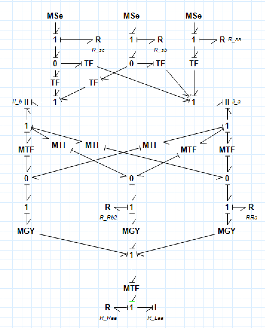
The enhanced Bond-Graph model is shown in Figure 10(b) which moved and
and  back-over the transformers in front of the phases. The Bond-Graph in Figure 10(b) depictions the interaction both stator coils and rotor bars with 2-port I-elements in the electrical energy area. An inductance only describes storage of magnetic energy. Overlooked are power losses and leakage effects in the magnetic area.
| 
|
(a) | (b) |
Figure 10. (a) Park reference frame of singly-fed induction generator; (b) Enhanced model
- RESULT AND DISCUSSION
With the view to demonstrate the performance of the steady state condition of the proposed Bond-Graph model, the wind turbine system simulation using the software 20-Sim with the numerical parameters that has been given (Table 2) is presented. The setup for simulation is as follows: a constant wind of 2 m/s is utilized at the simulation start. A wind turbine system comprises of 2.5 kW wind turbines is linked to a tower and a two-mass gearbox system to a RL load. The 2.5 kW wind turbine is simulated by three blades turbines. The induction generator is a SFIG. The blades, gearbox, tower, and SFIG are connected for the purpose to make the complete model of a constant-speed wind turbine as is shown in Figure 11.
Table 2 The SFIG parameters [34]-[36]
Components | Values |
Rated power | 2.5 kW |
Rated voltage | 220/380 V |
Number of pole pairs | 2 |
Rated speed | 1420 rpm |
Moment of inertia | 0.2 kg.m2 |
Stator resistance | 2.30 Ω |
Rotor resistance | 6.95 Ω |
Stator inductance | 0.040 H |
Rotor inductance | 0.036 H |
Mutual inductance | 0.061 H |
At Figure 12(a) a measured wind speed reach 2 m/second. It will be observed that the singly-fed induction generator speed reaches steady-state condition in approximately 4.6 seconds, seen in Figure 12(b). On the contrary to a constant wind input, the stator currents decline to a steady value, and generator velocity oscillation disappear. The stator currents oscillate at the input frequency with initial large amplitude, their response reflects their variability with wind, from 56 p.u. to 138 p.u., seen in Figure 12(c).
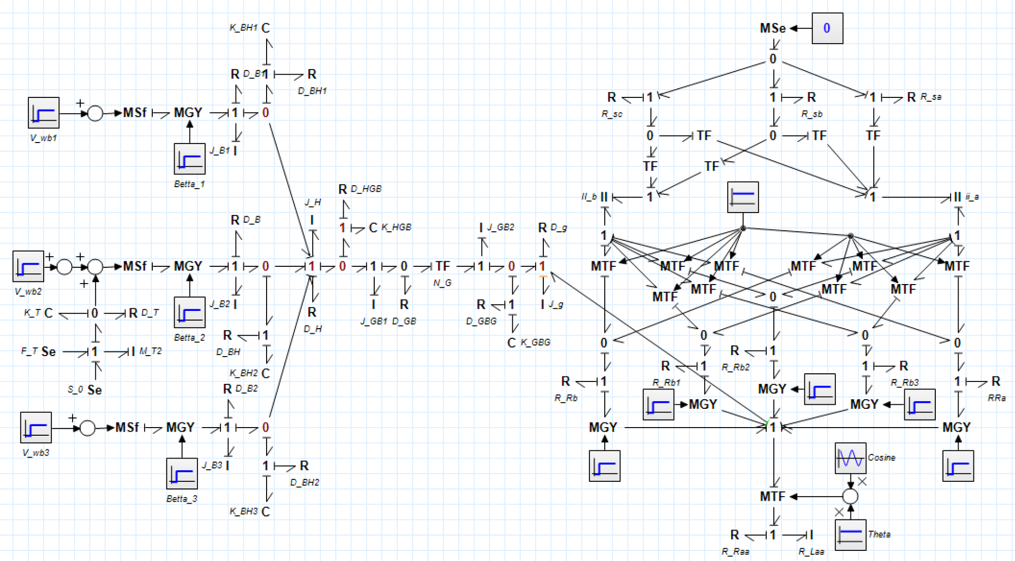
Figure 11. Constan wind speed simulation model with a SFIG
Figure 13 describes a wind turbine system comprises of 2.5 kW wind turbines is linked to a tower and a two-mass gearbox system to a RL load. Variable wind profile data is used. At Figure 14(b), measured gearbox speed reaches with a value of 120 N and it decreases to 95 N. Initially, the wind speed increases abruptly in the same ratio as the gearbox speed, i.e., up to the maximum value (around 1 p.u.) when the wind speed exceeds 2 m/s, shown in Figure 14(a). While the stator currents oscillate at the input frequency with initial small amplitude. After about 7.6 seconds, the generator reaches steady state. Here the stator currents increase to a steady value, and the value varies according to the loading value, from 76 p.u. to 116 p.u., seen in Figure 14(c).
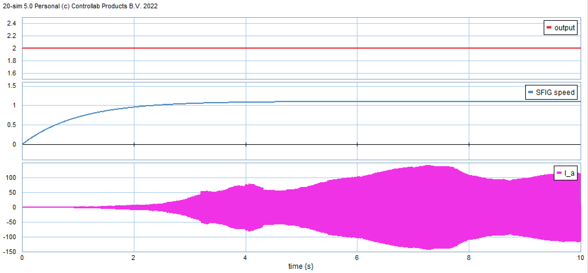
Figure 12. Responses for a constant wind profile (a) wind speed, (b) gearbox speed, (c) stator current of a SFIG
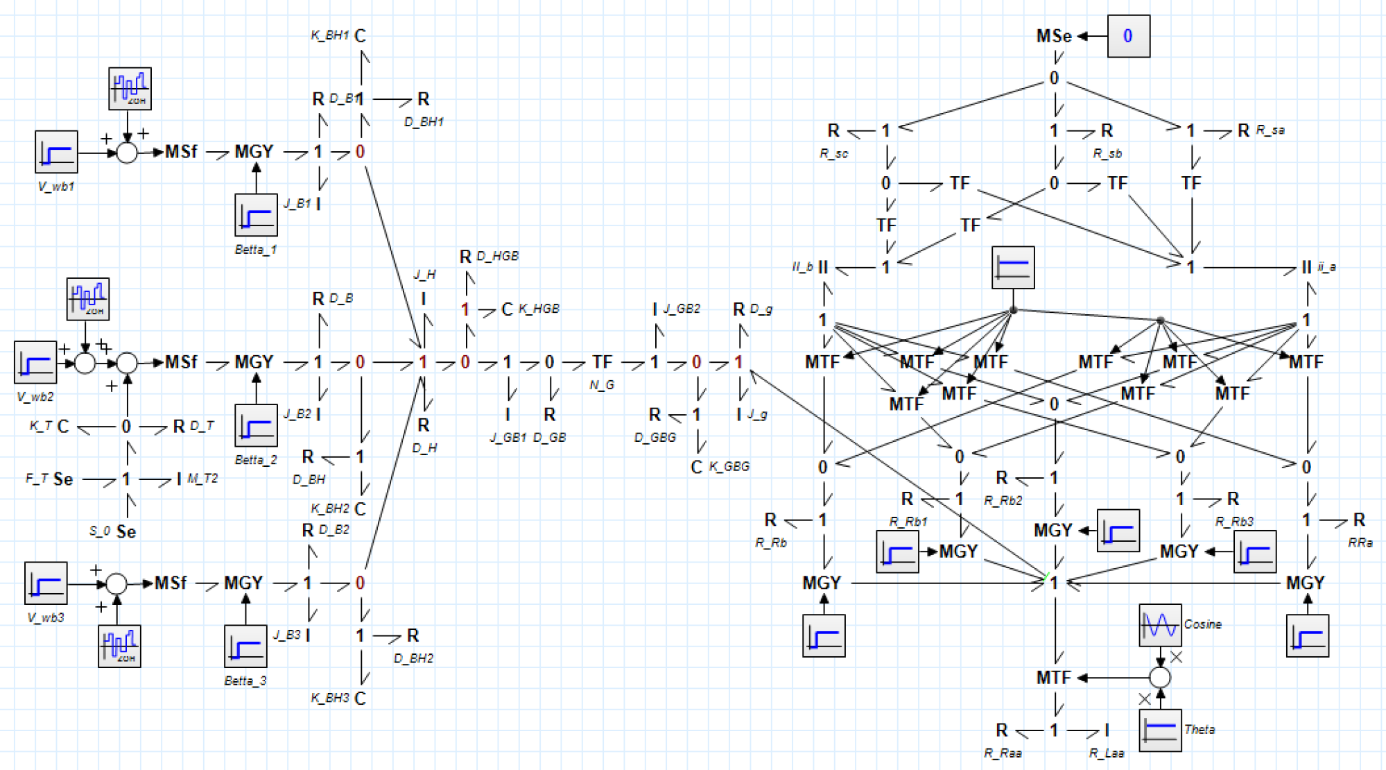
Figure 13. Variable wind speed simulation model with a SFIG
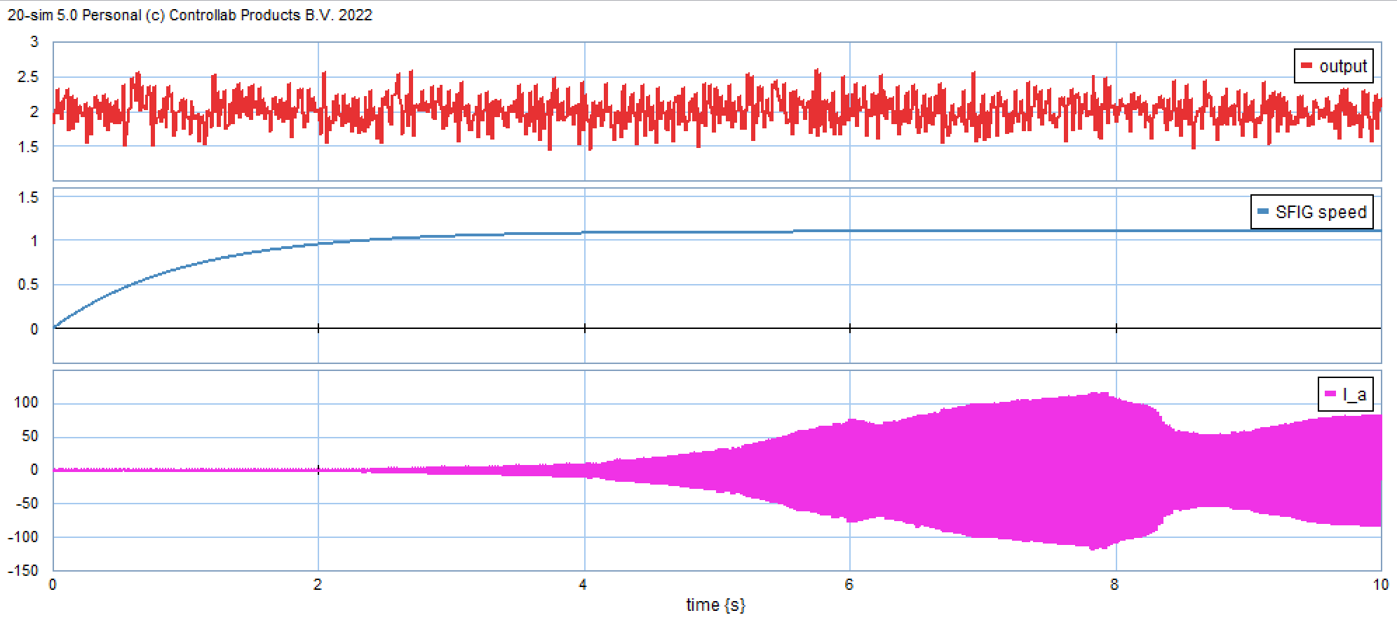
Figure 14. Responses for variablewind profile (a) wind speed, (b) gearbox speed, (c) stator current of a SFIG
- CONCLUSIONS
The aim of this paper is to make a nonlinear model of a wind turbine generating system with singly-fed induction generator by using the Bond-Graph approach. With the view to implement the aerodynamic force, blade structure is considered to be a flexible body. BEM theory has been applied for the wind aerodynamic force adaptation. Magnitudes of both torque and current in simulations have seen the legitimacy of the proposed model.
In contrast to a constant wind input, current response of singly-fed induction generator reflects their variability with wind, from 56 to 138 p.u. during a constant wind speed, such as 2 m/s. When the wind speed conditions vary increasing from 1.5 m/s to 2.5 m/s then the current response varies from 60.091 to 104.796 p.u. On the contrary, whether under constant (namely 2 m/s) or varying wind speed (from 1.5 m/s to 2.5 m/s) conditions, the response of generator speed and generator stator current tends to vary; the steady state nominal speed of generator is at 6.04 seconds and the stator current varies at ambient around 134.5 p.u.
The Bond-graph approach is unified, which means one can model many types of physical systems with the same methodology. To model a dynamic structure in the conventional way and Bond Graph method is moderately different, but the result is a model with precisely the same principal equations. It is also fitted to Bond Graph procedure offers superior interpretation of what occurred in the system.
Currently, most engineers must work and interact in many dissimilar disciplines. A thoughtful of the intersections of these distinctive disciplines is a valuable asset for some engineer. Based on the results in this study, interesting future research include accomplishment control design associated with wind turbine using Bond-Graph, such as an enhancement active and reactive power control methods on singly-fed induction generator using converters.
ACKNOWLEDGEMENT
This research has been fully subsidized by DRTPM, Dirjen Dikti Ristek, Kemdikbud Ristek under Grant no. 181/E5/PG.02.00.PL/2023, 0423.25/LL5-INT/AL.04/ 2023, and 03/ITNY/LPPMI/Pen.DRTPM/PFR/VII/ 2023.
REFERENCES
- J. S. Saranyaa and P. F. A, "A Comprehensive Survey on the Current Trends in Improvising the Renewable Energy Incorporated Global Power System Market," in IEEE Access, vol. 11, pp. 24016-24038, 2023, https://doi.org/10.1109/ACCESS.2023.3252574.
- T. Z. Ang, M. Salem, M. Kamarol, H. S. Das, M. A. Nazari, and N. Prabaharan, “A Comprehensive Study of Renewable Energy Sources: Classifications, Challenges and Suggestions,” Energy Strategy Revs., vol. 43, 2022, https://doi.org/10.1016/j.esr.2022.100939.
- M. Elgendi, M. AlMallahi, A. Abdelkhalig, and M. Y. E. Selim, “A review of Wind Turbines in Complex Terrain,” International Journal of Thermo-fluids, vol. 17, 2023, https://doi.org/10.1016/j.ijft.2023.100289.
- K. Dai, A. Bergot, C. Liang, W. N. Xiang, and Z. Huang, “Environmental Issues Associated with Wind Energy - A Review,” Renewable Energy, vol. 75, pp. 911-921, 2015, https://doi.org/10.1016/j.renene.2014.10.074.
- T. A. Hamed and A. Alshare, “Environmental Impact of Solar and Wind energy - A Review,” Journal of Sustainable Development of Energy, Water and Environment Systems, vol. 10, no. 2, 2022, https://doi.org/10.13044/j.sdewes.d9.0387.
- J. K. Kaldellis (Ed.). Stand-alone and hybrid wind energy systems: technology, energy storage and applications. Elsevier. 2010. https://books.google.co.id/books?hl=id&lr=&id=fIlwAgAAQBAJ.
- A. Bensalah, M.A. Benhamida, G. Barakat, and Y. Amara, “Large wind turbine generators: State-of-the-art review,” in Proceed. 2018 XIII International Conference on Electrical Machines (ICEM), vol. 2018, pp.2205-2211, 2018, https://doi.org/10.1109/ICELMACH.2018.8507165.
- O. E. Youssef, M. G. Hussien, and A. E. W. Hassan, “An Advanced Control Performance of a Sophisticated Stand‐Alone Wind‐Driven DFIG System,” International Transactions on Electrical Energy Systems, vol. 2023, no. 1, p. 5541932, 2023, https://doi.org/10.1155/2023/5541932.
- A. Afkari, F. E. Lamzouri, and E. Boufounas, “A Robust Controller for A Variable-speed Wind Turbine Using A Single Mass Model,” ICCSRE’2021, vol. 297, 2021, https://doi.org/10.1051/e3sconf/202129701042.
- B. Boukhezzar and H. Siguerdidjane, “Nonlinear Control of a Variable-Speed Wind Turbine Using aTwo-Mass Model,” IEEE Transactionson Energy Conversion, vol. 26, no. 1, pp. 149-162, 2011, https://doi.org/10.1109/TEC.2010.2090155.
- R. M. Imran, D. Hussain, and M. Soltani, “DAC to Mitigate the Effect of Periodic Disturbances on Drive Train using Collective Pitch for Variable Speed Wind Turbine,” in Conference: IEEE ICIT 2015, pp. 2588-2593, 2015, https://doi.org/10.1109/ICIT.2015.7125479.
- R. Iserman. Mechatronic design approach. Mechatronic Systems, Sensors, and Actuators: Fundamentals and Modeling. 2017. https://books.google.co.id/books?hl=id&lr=&id=xJwuDwAAQBAJ.
- A. Mohammed, B. Sirahbizu, and H. G. Lemu, “Optimal Rotary Wind Turbine Blade Modeling with Bond Graph Approach for Specific Local Sites,” Energies, vol. 22, 2022, https://doi.org/10.3390/en15186858.
- A. Gambier, “Dynamic Modelling of the Rotating Subsystem of a Wind Turbine for Control Design Purposes,” in IFAC-Papers OnLine, vol. 50, issue 1, pp. 9896-9901, 2017, https://doi.org/10.1016/j.ifacol.2017.08.1621.
- A. Ramdane, and A. Lachouri, “Modeling and Simulation of a Wind Turbine Driven Induction Generator Using Bond Graph,” Journal of Renewable Energy and Sustainable Development (RESD), vol. 1, no. 2, pp. 236-242, 2015, https://doi.org/10.21622/resd.2015.01.2.236.
- J. P.T. Mo and D. Chan, “Reliability Based Maintenance Planning of Wind Turbine Using Bond Graph,” Universal Journal of Mechanical Engineering, vol. 5, no. 4, pp. 103-112, 2017, https://doi.org/10.13189/ujme.2017.050401.
- B. Lu and A. Zanj, “Development of an Integrated System Design Tool for Helical Vertical Axis Wind Turbines (VAWT-X),” Energy Reports, vol. 8, pp. 8499-8510, 2022, https://doi.org/10.1016/j.egyr.2022.06.038.
- C. Fu, K. Lu, Y. D. Xu, Y. Yang, F. S. Gu, and Y. Chen,” Dynamic Analysis of Geared Transmission System for Wind Turbines with Mixed Aleatory and Epistemic Uncertainties,” Applied Mathematics and Mechanics, vol. 43, pp. 275-294, 2022, https://doi.org/10.1007/s10483-022-2816-8.
- M. B. Sliemene and M. A. Khlifi, “Persistent Voltage Control of a Wind Turbine-Driven Isolated Multiphase Induction Machine,” Engineering, Technology & Applied Science Research, vol. 13, no. 5, 2023, https://doi.org/10.48084/etasr.6330.
- O. Attallah, R. Ibrahim, and N. Zakzouk, “Fault Diagnosis for Induction Generator-based Wind Turbine Using Ensemble Deep Learning Techniques,” Energy Reports, vol. 8, pp. 12787-12798, 2022, https://doi.org/10.1016/j.egyr.2022.09.139.
- I. G. K. Polson, R. S. MohanKumar and N. Selvaganesan, "Control System Design for MIMO System using Bond graph Representation -Quadcopter as a Case Study," 2021 Seventh Indian Control Conference (ICC), Mumbai, India, 2021, pp. 39-44, 2021, https://doi.org/10.1109/ICC54714.2021.9703118.
- B. A. Alsati, G. I. Ibrahim, and R. R. Moussa, “Study the Impact of Transient State on the Doubly Fed Induction Generator for Various Wind Speeds,” Journal of Engineering and Applied Science, vol. 70, no. 65, 2023, https://doi.org/10.1186/s44147-023-00232-6.
- T Tarek Medalel Masaud and P. K. Sen, "Modeling and control of doubly fed induction generator for wind power," 2011 North American Power Symposium, pp. 1-8, 2011, https://doi.org/10.1109/NAPS.2011.6025122.
- W. A. Timmer and C. Bak, “Aerodynamic characteristics of wind turbine blade airfoils,” In Advances in wind turbine blade design and materials, pp. 129-167, 2023, https://doi.org/10.1016/B978-0-08-103007-3.00011-2.
- E. Branlard and E. Branlard, “The blade element momentum (BEM) method,” Wind Turbine Aerodynamics and Vorticity-Based Methods: Fundamentals and Recent Applications, pp. 181-211, 2017, https://doi.org/10.1007/978-3-319-55164-7.
- A. Gambier, “Dynamic Modelling of the Rotating Subsystem of a Wind Turbine for Control Design Purposes,” in IFAC-Papers OnLine, vol. 50, no. 1, pp. 9896-9901, 2017, https://doi.org/10.1016/j.ifacol.2017.08.1621.
- S. Simani, “Advanced Issues of Wind Turbine Modelling and Control,” 12th European Workshop on Advanced Control and Diagnosis (ACD2015), p. 659, 2015, https://doi.org/10.1088/1742-6596/659/1/012001.
- A. Mohammed and H. G. Lemu, “Wind Turbine System Modelling Using Bond Graph Method,” In Advanced Manufacturing and Automation VIII 8, pp. 95-105, 2019, https://doi.org/10.1007/978-981-13-2375-1_14.
- H. Bamdjid et al., "Photovoltaic/Wind Hybrid System Power Stations to Produce Electricity in Adrar Region," 2022 10th International Conference on Smart Grid (icSmartGrid), pp. 185-189, 2022, https://doi.org/10.1109/icSmartGrid55722.2022.9848677.
- Thomas C. Krause; Paul C. Krause, "Symmetrical Induction Machine," in Introduction to Modern Analysis of Electric Machines and Drives , pp.55-104, 2023, https://doi.org/10.1002/9781119908357.ch3.
- A. Parida and M. Paul, "A Novel Modeling of DFIG Appropriate for Wind- Energy Generation Systems Analysis," 2022 IEEE 10th Power India International Conference (PIICON), pp. 1-6, 2022, https://doi.org/10.1109/PIICON56320.2022.10045295.
- Z. D Guo, P. Korondi, and P. T. Szemes, “Bond-Graph-Based Approach to Teach PID and Sliding Mode Control in Mechatronics,” Machines, vol. 11, no. 10, p. 959, 2023, https://doi.org/10.3390/machines11100959.
- M. P. Kazmierkowski, "Induction Machines Handbook, Third Edition [Book News]," in IEEE Industrial Electronics Magazine, vol. 14, no. 4, pp. 185-186, 2020, https://doi.org/10.1109/MIE.2020.3031423.
- S. Cai, J. L. Kirtley and C. H. T. Lee, "Critical Review of Direct-Drive Electrical Machine Systems for Electric and Hybrid Electric Vehicles," in IEEE Transactions on Energy Conversion, vol. 37, no. 4, pp. 2657-2668, 2022, https://doi.org/10.1109/TEC.2022.3197351.
- H. Dehnavifard, M. A. Khan and P. S. Barendse, "Development of a 5-kW Scaled Prototype of a 2.5 MW Doubly-Fed Induction Generator," in IEEE Transactions on Industry Applications, vol. 52, no. 6, pp. 4688-4698, 2016, https://doi.org/10.1109/TIA.2016.2591512,
- A X. Yan and M. Cheng, "Backstepping-Based Direct Power Control for Dual-Cage Rotor Brushless Doubly Fed Induction Generator," in IEEE Transactions on Power Electronics, vol. 38, no. 2, pp. 2668-2680, 2023, https://doi.org/10.1109/TPEL.2022.3214331.
AUTHOR BIOGRAPHY

| Sugiarto Kadiman     he holds the Bachelor degree, Master degree, and Doctor degree in Electrical Engineering from Gadjah Mada University, Yogyakarta, Indonesia, in 1989, 2000, and 2014, respectively. Since 2014, he is working as Associate Professor in the Program Study of Electrical Engineering, Faculty of Industrial Technology, Institut Teknologi Nasional Yogyakarta, Yogyakarta, Indonesia. His research interest is model of Power System Analysis, Modelling and Simulation Systems, and Electronic Controlled Power Systems. He does research in The Dynamic of Synchronous Generator Under Unbalanced Steady State Operation and Unbalanced Transient Condition, Higher Order Model of Synchronous Generator, and Power System Stabilizer and PID Impacts on Transient condition in synchronous generator. The current project is Model Development and Control Design of Variable Speed Wind Power Plant with DFIG Configuration. He can be contacted at email: sugiarto.kadiman@itny.ac.id. he holds the Bachelor degree, Master degree, and Doctor degree in Electrical Engineering from Gadjah Mada University, Yogyakarta, Indonesia, in 1989, 2000, and 2014, respectively. Since 2014, he is working as Associate Professor in the Program Study of Electrical Engineering, Faculty of Industrial Technology, Institut Teknologi Nasional Yogyakarta, Yogyakarta, Indonesia. His research interest is model of Power System Analysis, Modelling and Simulation Systems, and Electronic Controlled Power Systems. He does research in The Dynamic of Synchronous Generator Under Unbalanced Steady State Operation and Unbalanced Transient Condition, Higher Order Model of Synchronous Generator, and Power System Stabilizer and PID Impacts on Transient condition in synchronous generator. The current project is Model Development and Control Design of Variable Speed Wind Power Plant with DFIG Configuration. He can be contacted at email: sugiarto.kadiman@itny.ac.id. |
|
|

| Oni Yuliani    she received the Bachelor degree in Chemical Engineering from Sriwijaya University, Palembang, Indonesia, in 1996. She received Master degree in Computer Science from Gadjah Mada University, Yogyakarta, Indonesia in 2006. Since 1994, she is working as Senior Lecturer in the Program Study of Electrical Engineering, Faculty of Industrial Technology, Institut Teknologi Nasional Yogyakarta, Yogyakarta, Indonesia. Her research interest includes Computer Algorithm and Program, and Probability and Stocastic Process. She can be contacted at email: oniyuliani@itny.ac.id. she received the Bachelor degree in Chemical Engineering from Sriwijaya University, Palembang, Indonesia, in 1996. She received Master degree in Computer Science from Gadjah Mada University, Yogyakarta, Indonesia in 2006. Since 1994, she is working as Senior Lecturer in the Program Study of Electrical Engineering, Faculty of Industrial Technology, Institut Teknologi Nasional Yogyakarta, Yogyakarta, Indonesia. Her research interest includes Computer Algorithm and Program, and Probability and Stocastic Process. She can be contacted at email: oniyuliani@itny.ac.id. |
|
|

| Diah Suwarti She received the Bachelor degree in Electrical Engineering from Sekolah Tinggi Teknologi Nasional, Yogyakarta, Indonesia, in 1998. She received Master degree in Electrical Engineering from Gadjah Mada University, Yogyakarta, Indonesia in 2011. Since 2012, she is working as Assistant Professor in the Program Study of Electrical Engineering, Faculty of Industrial Technology, Institut Teknologi Nasional Yogyakarta, Yogyakarta, Indonesia. Her research interest includes High Voltage and Electrical Power Protection. She can be contacted at email: diahsuwarti@itny.ac.id. |
Bond Graph Dynamic Modeling of Wind Turbine with Singly-feed Induction Generator (Sugiarto Kadiman)