Buletin Ilmiah Sarjana Teknik Elektro ISSN: 2685-9572
Efficiency Through Automation: A Single System for Multiple Railway Guard Posts
Mochammad Hisam Zulwidad, Indah Sulistiyowati
Department of Electrical Engineering Universitas Muhamadiyah Sidoarjo, East Java, Indonesia
ARTICLE INFORMATION |
| ABSTRACT |
Article History: Submitted 07 August 2023 Revised 15 September 2023 Accepted 02 October 2023 |
| 
One of the important factors in train travel is the guarding of railroad crossings. Unfortunately, the number of unguarded railway crossings is still quite large. This condition makes it prone to accidents, especially at crossings that are heavily traveled by vehicles. Most of the railway crossing guards in Indonesia use a manual system, where in this system one guard post can only guard one railway crossing, due to limited human resources from PT KAI, many railway crossing doors are not guarded. To reduce accidents and cover the lack of human resources from PT.KAI, an Efficiency tool through Automation was made: One System for Multiple Railway Crossing Guard Posts. This tool is equipped with several main components, namely PLC, HMI, Infrared Sensor, and servo motor. The crossing gate is fully controlled by PLC and HMI as a monitoring system for all components in real-time. By detecting the arrival of the train, the infrared sensor can work by utilizing the movement of the train passing the sensor, not only detecting the arrival of the train, the infrared sensor also works to give orders so that the Servo Motor as a crossing door can be immediately closed and opened on the miniature, the railroad crossing itself is also equipped with an infrared sensor that functions to detect the presence of vehicles in the middle of the railroad crossing controlled by PLC and HMI as a monitoring system. This tool has been tested and the device functions properly and can help reduce the accident rate at railroad crossings. |
Keywords: Railway Safety; Automation; Guard Posts |
Corresponding Author: Indah Sulistiyowati, Department of Electrical Engineering, Universitas Muhammadiyah Sidoarjo, East Java, Indonesia. Email: indah_sulistiyowati@umsida.ac.id |
This work is licensed under Creative Commons Attribution-Share Alike 4.0 
|
Document Citation: M. H. Zulwidad and I. Sulistiyowati, “Efficiency Through Automation: A Single System for Multiple Railway Guard Posts,” Buletin Ilmiah Sarjana Teknik Elektro, vol. 5, no. 3, pp. 407-416, 2023, DOI: 10.12928/biste.v5i3.9001. |
- INTRODUCTION
Technology advancements will inevitably accompany scientific advancements thus, it is impossible to prevent them in this life [1]. The railroad crossing door is a technological invention that has been tremendously beneficial to people [2]. Railroad crossing gates are used to secure train transit so as not to obstruct human or other motorized vehicle traffic [3]. Government Regulation No. 72 of 2009 regarding Railway Traffic and Transportation, Article 110, Paragraph 4, states this. "Train traffic is prioritized because road users must give the train priority because, in the event of a collision, the effect and costs sustained may be greater [4]. Accordingly, the crossing gate's primary purpose is to secure train traffic, according to Joni Martinus, vice president of public relations at KAI (KAI, 12.10.2020). Railroad crossing gates have both advantageous and unfavorable consequences in daily life [5].
The purpose of a train doorstop is to aid human activity, however, some flaws in the design have led to several accidents that were the result of communal negligence [6]. Because it affects the community's standard of living, Governor Khofifah underlined the significance of enhancing security around railroad tracks [7]. People who desire to cross the railroad tracks, for instance, may risk their lives if there is no Early Warning System (EWS) in place, such as a siren [8]. In addition, there are 1,290 railroad crossings in East Java alone, including 1,140 level crossings and 150 level crossings, according to Khofifah. The local government guards 72 crossings, KAI guards 280 crossings, volunteers patrol 127 crossings, and 470 crossings are unsecured [9].
An automated control system called an automatic railroad crossing is utilized to raise the level of safety for both road users and the train itself [10]. When a train passes by, the system opens and closes the crossbar on its own [11]. There has been a lot of research done to create and build more effective and efficient automatic control systems as the use of automation technology at railway gate crossings has increased recently [12][13].
To enhance, update, and address issues that have already been studied, this research was conducted using literacy in various prior studies. In previous research, the use of an automatic train doorstop using an Arduino microcontroller and HC-SR04 sensor [14][15]. This research is smaller than the research done by the author since it was able to manage 5 automatic train door bars simultaneously with 1 tool, meaning that with this tool 1 guard post may control 5 train door bars simultaneously.
Previous researchers explained the use of the Telegram BOT-based Railway Automatic Door Crossing System Design [16]. This research is considered less effective in terms of monitoring because to carry out telegram control the user must create a bot which is quite complicated when compared to using HMI to monitor the train doorstop. In addition, the telegram application is still less effective because the railroad crossing guard still needs time to operate the cell phone, so a lot of time is wasted.
Automated railroad crossing technology has now replaced manual crossing technology [17]. The train doorstop is made safer and more effective by incorporating technology into its parts as it advances [18][19]. To solve this problem, we created PAK SUMA: Innovation of Railway Door Crossing, One Tool for Five Guard Posts. Here, we'll create an HMI (Human Machine Interface)-monitored PLC-based automatic train doorstop. To make up for the absence of human resources, we can run five guard stations with the tools we create. This doorstop can set the time so that it will automatically close if a train passes and open if the train does not pass. It also can alert guard officers and train users when there are still people standing in the middle of the train tracks after the gates are closed. Thanks to this tool, it is hoped that accidents at railway crossings can be reduced. It is hoped that this PLC-based automatic train doorstop with HMI monitoring will be a technological advancement in the world of railways as well as a solution to reduce the frequency of accidents caused by trains.
- METHODS
The Research and Development (R&D) research technique was utilized in this study to update and develop earlier studies by reviewing earlier studies to make changes and renewals that would produce new results that would be useful and effective for the larger population [20]. Making block diagrams, creating flowcharts, and creating wiring diagrams are the three methods covered in this chapter [21]. although each phase serves a distinct purpose, all three processes are ultimately interconnected with the construction of an efficient prototype that will benefit the larger community as a whole as their final aim [22].
System Block Diagram
The research block diagram is made to facilitate the design and manufacture of tools, the block diagram in this study is shown in Figure 1.
The input section consists of two parts, each of which is an infrared sensor. One of the infrared sensors detects whether a train is approaching, and the other determines whether there are still vehicles at the railroad crossing when the train gate is closed. This determines whether there is a train.
The Outsel V3 PLC microcontroller data processing component used has many advantages compared to the previous Outsel PLC series, one of which is that it has more pins. In terms of data processing from the input section and command messages from the associated HMI, PLC performs this task better than other microcontrollers. As the last step in this circuit, the microcontroller will send the processed data to the output stage. Because PLC outsells V3 has a system that can be connected to the HMI so that it may deliver data in real-time to the user through the HMI, PLC outsells V3 is used as a data communication medium between the tool and the user. Before entering the servo motor, PLC output data for the command to close the railroad crossing must first be input into Arduino and the pca9685 set module.
The output part is in the form of a servo motor and buzzer, with the servo motor functioning to move the railroad crossing gate and the buzzer to alert the driver and officers to the presence of vehicles at the railroad crossing. HMI is used to monitor the entire series of tools.
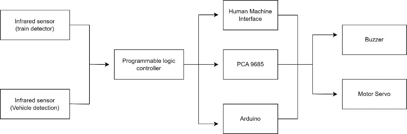
Figure 1. Block diagrams
System Flowchart
A flowchart is a research flowchart from the beginning of the process to the end which is made to facilitate the research process. In this study, there are 2 flowcharts consisting of the flowchart of the entire tool and the HMI monitoring system flowchart. Figure 2 is the first flowchart which shows the entire flow of the circuit from the initial condition where all system components are turned on, to the two infrared sensors in the input section, where infrared sensor 1 functions to detect the presence of an approaching train and infrared sensor 2 functions to detect the presence of vehicles that are still at a railroad crossing.
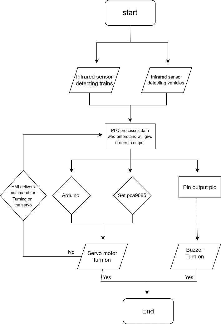
Figure 2. Tool set flowchart
Once the microcontroller has processed the sensor's data, it will send it to the output when infrared sensor 1 detects a passing train. When the train approaches the railroad crossing, the servo motor rotates, closing the railroad crossing. It then rotates to reopen the railroad crossing. A manual mechanism is also included with this tool, allowing the train doorstop to be closed manually via an HMI if the sensor were to unexpectedly become defective. Infrared sensors are installed at railway crossing gates. This sensor detects whether the vehicle is still at the railroad crossing. If so, the buzzer will activate to warn the driver to immediately get out of the car to prevent a fatal accident.
The second flowchart, Figure 3, shows the monitoring circuit of the automatic railroad door crossing tool for five guard posts. The microcontroller will begin sending data to the HMI in real-time when the door crossing is operational, allowing the railroad door crossing officer to continuously monitor which door crossings are operational and which are not. The HMI layer's indicator will turn on when doorstop 1 is engaged if doorstop 1 is not engaged, the program will end and the indicator will go out.
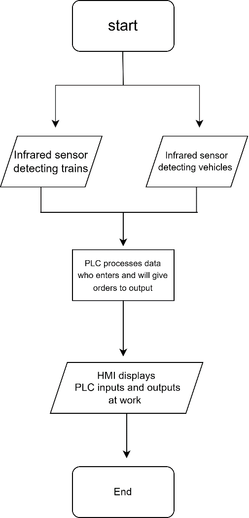
Figure 3. Monitoring series flowchart
Wiring Diagram
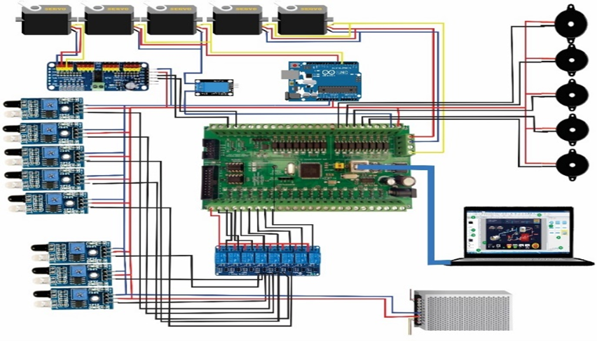
Figure 4 shows the wiring design for the wiring circuit utilized in this study. As can be seen, the PLC Mega V3 microcontroller is used to connect all of the components used as inputs and outputs. The tools must be correctly connected with all of the components for them to be used and function at their best. In Figure 4 there are several components used and their uses are as follows:
- Infrared sensor 1 as a train detection component.
- Infrared sensor 2 is used as a detector if there are vehicles that are still at the railroad crossing when the crossbar is closed.
- The Mega V3 PLC microcontroller is used as the brain of the circuit, its job is to process the data received by the sensor and then forward it to the output component.
- Arduino is used as a module for servo motors, plc commands will be processed by Arduino so that they can be read by servo motors.
- The PCA9685 Driver Set is used as a module for servo motors, plc commands will be processed by the PCA9685 Set so that they can be read by servo motors.
- The servo motor is used as the output that will rotate to move the railroad doorstop.
- The buzzer is used as an output that will make a sound if there is a vehicle that is still at the railroad crossing when the crossing bar is closed.
- HMI is used as a component that can see the entire system working correctly according to the desired system.
The pin address of each connected component can be seen in Table 1. The servo motor pin is directly attached to the module being used, which is an Arduino or a set-pca9685. These modules will operate if they get a command from the plc output, which is R1 to R5. Pins R6 through R10 will connect to the buzzer. While we immediately connect the buzzer's VCC supply to pin 5v of the PLC, the servo motor requires VCC and ground from the Arduino pin and setpca9685. We use the PLC's USB pin, which is already there, to connect the HMI directly.
All sensors that are utilized as wiring lines have three pins, the first of which is used as an input for reading the analog value the sensor produces. Next comes VCC, which serves as a source of power for the sensor, and GND, which serves as grounding. We use a parallel circuit to power all of the sensors' VCC and GND wiring lines by stepping down a 12v power source to 5v. The required power source comes from a 12v power supply.
Table 1. Component pin addresses
No. | Component | Component Pin Address | Pin Address Mega V3 PLC |
| No. | Component | Component Pin Address | Pin Address Mega V3 PLC |
1. | Servo motor (Railway crossing 1) | VCC GND Pwm Pin | R1 |
| 12. | Infrared sensor (Crossbar warning system 4) | VCC GND Pinout | S7 |
2. | Servo motor (Railway crossing 2) | VCC GND Pwm Pin | R2 |
| 13. | Infrared sensor (Crossbar warning system 5) | VCC GND Pinout | S8 |
3. | Servo motor (Railway crossing 3) | VCC GND Pwm Pin | R3 |
| 14. | Arduino | Pin 4 Pin 5 VCC GND | R11 |
4. | Servo motor (Railway crossing 4) | VCC GND Pwm Pin | R4 |
| 15. | Modul PCA9685 | VCC GND Pin PWM | SDA SCL VCC GND |
5. | Servo motor (Railway crossing 5) | VCC GND Pwm Pin | R5 |
| 16. | Buzzer (Crossbar 1 warning system) | VCC GND | R6 VCC |
6. | Infrared sensors (Crossbars 1 and 2) | VCC GND Pinout | S1 |
| 17. | Buzzer (Crossbar 2 warning system) | VCC GND | R7 VCC |
7. | Infrared sensors (Crossbars 3 and 4) | VCC GND Pinout | S2 |
| 18. | Buzzer (Crossbar 3 warning system) | VCC GND | R8 VCC |
8. | Infrared sensors (Crossbars 5) | VCC GND Pinout | S3 |
| 19. | Buzzer (Crossbar 4 warning system) | VCC GND | R9 VCC |
9. | Infrared sensor (Crossbar warning system 1) | VCC GND Pinout | S4 |
| 20. | Buzzer (Crossbar 5 warning system) | VCC GND | R10 VCC |
10. | Infrared sensor (Crossbar warning system 2) | VCC GND Pinout | S5 |
| 21 | HMI | USB | USB |
11. | Infrared sensor (Crossbar warning system 3) | VCC GND Pinout | S6 |
|
|
|
|
|
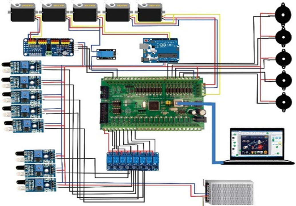
Figure 4. Wiring diagram
- RESULTS AND DISCUSSION
Figure 5 shows the results of a prototype automatic train door with one device for five guard posts. The following numbers will be used to describe each component: 1. PLC Mega V3, 2. Step down, 3. Arduino, 4. Relay, 5. Power supply, 6. Set PCA9685, 7.MCB, 8. Buzzer, 9. Servo motor, 10. Infrared sensor.
How to operate the prototype is as follows:
- The user turns on the MCB that has been connected to the power supply source.
- After turning on the MCB, the system will be in the standby position.
- Once the system is in standby position, we can directly run the train to simulate the doorstep.
If the train detection sensor is not working, we can immediately turn on the manual railroad crossing system by directly pressing the push on the HMI screen.
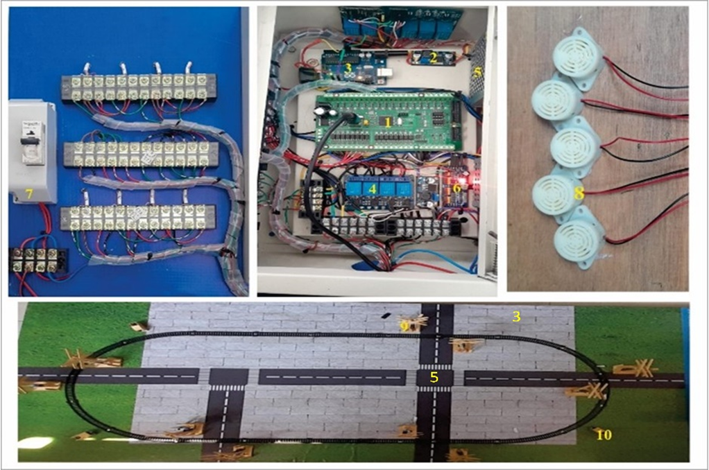

Figure 5. Tool realization
- Testing the Connection between the HMI and the Mega V3 PLC
To make sure the Mega V3 PLC microcontroller can connect to the intended HMI, testing is done. When the Mega V3 PLC microcontroller was connected to an HMI, testing was done repeatedly to determine how long the waiting time was. The results are shown in Table 2.
Table 2. Testing the HMI connection with the Mega V3 PLC
Testing- | PLC Mega V3 microcontroller | Accuracy |
Conditions | Waiting Time |
Test 1 | Connected | 4.15 Second | Good |
Test 2 | Connected | 4.09 Second | Good |
Test 3 | Connected | 2.84 Second | Good |
Test 4 | Connected | 3.09 Second | Good |
Test 5 | Connected | 3.48 Second | Good |
The Mega V3 PLC microcontroller testing results are shown in Table 2. The results indicate that the microcontroller was tested five times and that it can be connected correctly. However, the waiting time that was produced in each test varied, but the difference could still be considered to be typical because it was not too great.
- Testing the Infrared Sensor for Train Detection
Three tests were conducted on the infrared sensor, the first of which was to make sure that all of the parts were functional and in good condition. Table 3 contains the test results. The railroad gate will be closed when the sensor detects a train, as shown in Table 3, and open when the sensor does not detect a train.
Table 3. Train detection infrared sensor testing
Test to- | Conditions | Sensors detect trains | Reading result |
YES | NO |
First test | Connected | ME | 0 | Closed crossbar |
0 | ME | Open crossbar |
Test – 2 | Connected | ME | 0 | Closed crossbar |
0 | ME | Open crossbar |
Test – 3 | Connected | ME | 0 | Closed crossbar |
0 | ME | Open crossbar |
- Vehicle Detection Infrared Sensor Testing
Testing infrared sensors for vehicle detection This test is carried out to find out if the early warning system works properly. The results of component testing can be seen in Table 4. The tests performed above demonstrate that the buzzer will activate when the railroad gate is closed and the sensor determines that there are still vehicles at the railroad crossing. Less than two seconds pass before the buzzer responds. The buzzer won't sound if the railroad crossing is locked up and there are no cars there.
Table 4. Vehicle detection infrared sensor test
Test to- | Component Condition | Railroad crossing conditions | Condition of railroad crossing | Buzzer response time | Reading result |
First test | Connected | No vehicle | Closed | 0 | Buzzer not on |
Test – 2 | Connected | There is a vehicle | Closed | 1.40 Second | Buzzer on |
Test – 3 | Connected | There is a vehicle | Open | 0 | Buzzer not on |
Test – 4 | Connected | There is a vehicle | Closed | 1.26 Second | Buzzer on |
- Testing the Length of Time the Train Passes the Crossbar
Testing the time it takes for a train to pass through a railroad crossing can be found by applying the formula T = S / V where T = time, S = distance, and V = speed. By applying the formula, we can determine the time it takes for the train to pass through the railroad crossing. The test results can be seen in Table 5.
In the table of test results, Table 5 the time it takes for the train to pass through the railroad door crossing is different because the railroad door crossings 1 and 2 will close simultaneously. After all, the distance between the crossings is close to where it does not reach 30 meters, while the 5th railroad door crossing is quite far away so it does not close simultaneously. So the time it takes for the train to pass through the railroad crossing there is different. For each crossbar, we do a trial of 3 times with the same speed and the resulting value is not the same There is a difference in each trial but with a difference that is not so much it can be concluded that it can work well.
Table 5. Tests on the length of time the train passes through the railroad crossing
Test to- | Conditions | Railway door crossing | The time it takes for a train to pass through a railroad crossing | Condition of railroad crossing | Percentage accuracy |
First test | Connected | Railway door crossing 1 & 2 | 5.25 Second | Closed | 93% |
Test – 2 | Connected | Railway door crossing 1 & 2 | 6.41 Second | Closed | 85% |
Test – 3 | Connected | Railway door crossing 1 & 2 | 6.08 Second | Closed | 97% |
Test – 4 | Connected | Railway door crossing 3 & 4 | 6.55 Second | Closed | 97% |
Test – 5 | Connected | Railway door crossing 3 & 4 | 6.68 Second | Closed | 95% |
Test – 6 | Connected | Railway door crossing 3 & 4 | 6.62 Second | Closed | 91% |
Test – 7 | Connected | Railway door crossing 5 | 3.74 Second | Closed | 90% |
Test – 8 | Connected | Railway door crossing 5 | 3.54 Second | Closed | 86% |
Test – 9 | Connected | Railway door crossing 5 | 3.61 Second | Closed | 96% |
- Testing the Railroad Door Crossing
Testing is done to find out if the 5 door bars that we will control function properly as expected. The test results can be seen in Table 6. The test results above show that all railroad crossings function properly.
Table 6. Testing the railroad door crossing
Test to- | Conditions | Working railroad crossing | Condition of train doorstops | Accuracy |
First test | Connected | Railroad crossing 1 | Closed | Good |
Test – 2 | Connected | Railroad crossing 2 | Closed | Good |
Test – 3 | Connected | Railroad crossing 3 | Closed | Good |
Test – 4 | Connected | Railroad crossing 4 | Closed | Good |
Test – 5 | Connected | Railroad crossing 5 | Closed | Good |
- Manual System Testing Using HMI
This HMI must be connected to the PLC first by equating the input and output data of the PLC with the data that will be received by the HMI. This is necessary for testing the manual system of automatic railroad door crossing one tool for five guard posts. We utilize a USB cable to transfer data between the HMI and PLC. The HMI can then be used after the PLC and HMI have been connected. The user merely needs to push the layer button on the HMI to start it running; the microcontroller will react and carry out the command. Which bars are open and which are closed will be disclosed by HMI in real-time. Figure 6 displays the test results. The railroad crossing officer can take immediate action in this case by pressing the crossbar you want to manually close on the HMI screen when the infrared sensor detects the train is malfunctioning.
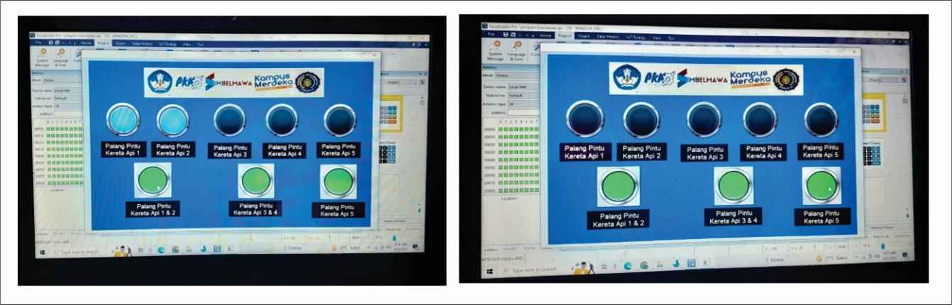
Figure 6. HMI menu
- CONCLUSION
Based on the results of the tests, it can be said that, even though there is a time gap between tests, with a small enough delay, it can still be said that all of the used components can perform optimally. The infrared sensor was tested for its ability to detect trains, and the results were quite promising: in each trial, 97% of the sensors worked as intended, and the infrared sensor accounted for a sizable portion of the sensors utilized to do so. Due to the abrupt fall in train speed, the open crossbar returns after passing through the railroad crossing with an average accuracy of 92.2%, but with a level on average that is still within acceptable bounds. When the railroad crossing is closed, the infrared sensor is tested to see if it can detect vehicles there. When it does, the process of sending data that the sensor has read to turn on the buzzer only takes an average of 1.33 seconds. This suggests that the system's existence may be able to lower the number of fatal accidents. At the railroad crossing, we also tested the infrared sensor for vehicle recognition with the doorstop open and closed but without any vehicles present, and we obtained the results of the buzzer not activating. HMI was used to test the manual system for automatic train door crossing, and it was successful. With HMI, we may close the train door crossing by just pressing a button on the HMI screen. This HMI also has a monitoring system that can track the status of the door bars around the clock. The prototype can be strengthened where it has flaws, such as its inability to distinguish between trains and other moving objects, or its inability to solve issues if there are objects that obstruct the doorstop when closing or opening. Additional research is advised to maximize the results of this study. The technical and financial viability of this system using actual rails and trains needs to be explored more thoroughly in the following stage.
ACKNOWLEDGEMENTS
The author would like to thank the Department of Electrical Engineering, Faculty of Science and Technology, University of Muhammadiyah Sidoarjo for their support. This work and research is supported and funded by DIKTIRISTEK, KEMENDIKBUDRISTEK through the student creativity program (PKM 2023).
REFERENCES
[1] D. V. Efanov, G. V. Osadchii, and V. V. Khoroshev, “New Stage in Safety Traffic Control Technologies Development: Digital Railroad Crossing,” in 2019 International Russian Automation Conference (RusAutoCon), pp. 1–6, 2019, https://doi.org/10.1109/RUSAUTOCON.2019.8867700.
[2] Y. Guo, L. Wan, Y. Zhou, Z. Zhang, and M. Yuan, “Research on the Degradation Process Analysis of the Rail Transit Door System,” in 2020 Global Reliability and Prognostics and Health Management (PHM-Shanghai), pp. 1–5, 2020, https://doi.org/10.1109/PHM-Shanghai49105.2020.9280920.
[3] M. Rath, “Smart traffic management system for traffic control using automated mechanical and electronic devices. In IOP Conference Series: Materials Science and Engineering, vol. 377, no. 1, p. 012201, 2018, https://doi.org/10.1088/1757-899X/377/1/012201.
[4] M. Hamadache, S. Dutta, R. Ambur, O. Olaby, E. Stewart, and R. Dixon, “Residual-based Fault Detection Method: Application to Railway Switch & Crossing (S&C) System,” in 2019 19th International Conference on Control, Automation and Systems (ICCAS), pp. 1228–1233, 2019, https://doi.org/10.23919/ICCAS47443.2019.8971747.
[5] E. Y. Narusova and V. G. Struchalin, “Developing Architecture of Electronic Means of Ensuring the Safe Crossing of Railway Tracks,” in 2021 International Conference on Quality Management, Transport and Information Security, Information Technologies (IT&QM&IS), pp. 85–89, 2021, https://doi.org/10.1109/ITQMIS53292.2021.9642860.
[6] M. I. M. Amjath and T. Kartheeswaran, “An Automated Railway Level Crossing System,” in 2020 International Conference on Image Processing and Robotics (ICIP), pp. 1–7, 2020, https://doi.org/10.1109/ICIP48927.2020.9367346.
[7] K. Shimura, Y. Tomioka, and Q. Zhao, “An Efficient Scene Recognition System of Railway Crossing,” in 2020 11th International Conference on Awareness Science and Technology (iCAST), pp. 1–6, 2020, https://doi.org/10.1109/iCAST51195.2020.9319497.
[8] P. Sikora, M. Kiac, and M. K. Dutta, “Classification of railway level crossing barrier and light signaling system using YOLOv3,” in 2020 43rd International Conference on Telecommunications and Signal Processing (TSP), 2020, https://doi.org/10.1109/TSP49548.2020.9163535.
[9] N. C. Brintha, C. V. P. Tarun, L. Abhishikth, B. P. K. Rao, and M. T. Reddy, “Smart Railway Crossing Surveillance System,” in 2022 International Conference on Computing, Communication, Security and Intelligent Systems (IC3SIS), pp. 1–5, 2022, https://doi.org/10.1109/IC3SIS54991.2022.9885699.
[10] B. P. P. Varna, D. Bhaskar, A. H. M, and V. K. Agrawal, “Solution to Unmanned Railway Crossing Using Satellite and GPS Based Approach,” in 2018 4th International Conference for Convergence in Technology (I2CT), pp. 1–4, 2018, https://doi.org/10.1109/I2CT42659.2018.9058149.
[11] A. A. Amusan and Y. K. Adebakin, “An Automatic Railway Level Crossing System with Crack Detection,” in 2022 5th Information Technology for Education and Development (ITED), pp. 1–7, 2022, https://doi.org/10.1109/ITED56637.2022.10051357.
[12] Z. Wang and L. Liu, “Research on Linkage Control Strategy of Train Door and Platform Door Based on Automatic Driving Technology,” in 2019 IEEE 3rd Information Technology, Networking, Electronic and Automation Control Conference (ITNEC), pp. 1989–1992, 2019, https://doi.org/10.1109/ITNEC.2019.8729537.
[13] E. N. Ardina, E. D. Wardihani, and S. B. Kuntardjo, “The Track Characteristics and The Propagation Model in Train Traffic For Automatic Traffic Door System,” in 2019 6th International Conference on Information Technology, Computer and Electrical Engineering (ICITACEE), pp. 1–62019, https://doi.org/10.1109/ICITACEE.2019.8904223.
[14] K. Shimura, Y. Tomioka, and Q. Zhao, “A Distance Estimation Method to Railway Crossing Using Warning Signs,” in 2021 IEEE 14th International Symposium on Embedded Multicore/Many-core Systems-on-Chip (MCSoC), pp. 178–181, 2021, https://doi.org/10.1109/MCSoC51149.2021.00034.
[15] A. Rehman, S. Latif, and N. A. Zafar, “Automata Based Railway Gate Control System at Level Crossing,” in 2019 International Conference on Communication Technologies (ComTech), pp. 30–35, 2019, https://doi.org/10.1109/COMTECH.2019.8737833.
[16] K. R. Ahmed, M. A. Hossain, A. Akter, and L. Akthar, “A Secure Automated Level Crossing and Train Detection System for Bangladesh Railway,” in 2022 International Conference on Advancement in Electrical and Electronic Engineering (ICAEEE), pp. 1–4 2022, https://doi.org/10.1109/ICAEEE54957.2022.9836361.
[17] C. Du, S. Dutta, P. Kurup, T. Yu, and X. Wang, “A review of railway infrastructure monitoring using fiber optic sensors,” Sensors and Actuators A: Physical, 303, 111728, 2020, https://doi.org/10.1016/j.sna.2019.111728.
[18] S. Surya, P. Kausik, G. Diyaneshwaran, and R. Raffik, “Railway Gate Automation Using Onboard Computing Techniques,” in 2023 2nd International Conference on Advancements in Electrical, Electronics, Communication, Computing and Automation (ICAECA), pp. 1–4, 2023, https://doi.org/10.1109/ICAECA56562.2023.10200564.
[19] A. S. Pashina, D. A. Trofimov, R. R. Savchuk, and M. V Tokareva, “Organization of Efficient Power Supply for the Railway Crossing Signaling System,” in 2020 IEEE Conference of Russian Young Researchers in Electrical and Electronic Engineering (EIConRus), pp. 1652–1654, 2020, https://doi.org/10.1109/EIConRus49466.2020.9039194.
[20] E. J. Lourenço, M. Oliva, M. A. Estrela and A. J. Baptista, "Multidimensional Design Assessment Model for eco-efficiency and efficiency in aeronautical assembly processes," 2019 IEEE International Conference on Engineering, Technology and Innovation (ICE/ITMC), pp. 1-9, 2019, https://doi.org/10.1109/ICE.2019.8792641.
[21] S. Singh, M. Zuber, M. N. Hamidon, N. Mazlan, A. A. Basri, and K. A. Ahmad, “Classification of actuation mechanism designs with structural block diagrams for flapping-wing drones: A comprehensive review,” Progress in Aerospace Sciences, vol. 132, p. 100833, 2022, https://doi.org/10.1016/j.paerosci.2022.100833.
[22] M. I. DeLosRíos-White, P. Roebeling, S. Valente, and I. Vaittinen, “Mapping the life cycle co-creation process of nature-based solutions for urban climate change adaptation,” Resources, vol. 9, no. 4, p. 39, 2020, https://doi.org/10.3390/resources9040039.
AUTHOR BIOGRAPHY

| Mochammad Hisam Zulwidad, was born in the city of Sidoarjo on May 27, 2002, his first education was MI he graduated in 2012, then continued his education at SMPN 1 Buduran, and in 2020 completed his education in electrical power installation engineering at SMKN 1 Sidoarjo which is located in the middle of Sidoarjo city. In 2020 continued his education to get his first bachelor's degree (S1) at Muhammadiyah Sidoarjo University with an Electrical Engineering study program.
|
|
|

| Indah Sulistiyowati, is a researcher specializing in Renewable Energy Power Systems and Control Systems. He completed his master's degree at the Sepuluh Nopember Institute of Technology majoring in Electrical Engineering Control Systems, and is now a lecturer at Muhammadiyah Sidoarjo University. |
Efficiency Through Automation: A Single System for Multiple Railway Guard Posts
(Mochammad Hisam Zulwidad)