Buletin Ilmiah Sarjana Teknik Elektro ISSN: 2685-9572
Motion-Making Messenger Robot 1 at the ABU Indonesia Robot Contest 2019 Using the Odometry Method
Dody Kurniawan, Wahyu Sapto Aji
Department of Electrical Engineering, Universitas Ahmad Dahlan, Yogyakarta, Indonesia
ARTICLE INFORMATION |
| ABSTRACT |
Article History: Submitted 21 June 2022 Revised 18 January 2023 Accepted 21 January 2023
|
| 
This research discusses the development of robot messenger 1 movement at the ABU Indonesia 2019 robot contest using odometry. To navigate at the time of the group, the Messenger Robot 1 robot is still operated manually. The disadvantage of manual operation of the robot is that the navigation of the robot is very dependent on the operation of the operator so that the robot is not accurate. Then a system is needed for navigation so that the robot can move accurately. Using the odometry method, it can estimate the change in position relative to the starting position. The positioning of the robot uses a rotary encoder to adjust the speed of the DC motor, according to the specified setpoint and determine the direction of motion of the robot. The test results of the odometry method using rotary encoder sesnor on simple motion, namely forward motion obtained an average error at the X coordinate point of -0.58 cm and at the Y coordinate of -3.02 cm, while in reverse motion obtained an average error, namely at the X coordinate point of 0.39 cm and at the Y coordinate of 3.03 cm. Based on these results it can be concluded that the robot can move literally with a fairly good level of accuracy.
|
Keywords: Robot; Odometry; Rotary; Encoder; Motor DC; PID
|
Corresponding Author: Wahyu Sapto Aji, Department of Electrical Engineering, Universitas Ahmad Dahlan, Indonesia. Email: wahyusa@ee.uad.ac.id |
This work is licensed under a Creative Commons Attribution-Share Alike 4.0 
|
Document Citation: D. Kurniawan and W. S. Aji, “Motion-Making Messenger Robot 1 at the Abu Indonesia Robot Contest 2019 Using the Odometry Method,” Buletin Ilmiah Sarjana Teknik Elektro, vol. 4, no. 3, pp. 172-185, 2021, DOI:10.12928/biste.v4i3.6191. |
- INTRODUCTION
The Universitas Ahmad Dahlan robot team made two robots, one of which is a manual robot called Messenger Robot 1 (MR1) which is allowed to navigate fully automatically or semi-automatically. The right system is needed so that the robot can navigate to the destination coordinates accurately and quickly [1]. To navigate during the competition, generally the Messenger Robot 1 robot is still operated manually. The weakness of manual robot operation is that robot navigation is very dependent on operator operation so that the robot is not accurate. So a system is needed for navigation so that the robot can move accurately.
Odometry is the use of data from movement sensors to estimate position changes relative to the initial position [2][3]. Wheeled robot positioners generally use rotary encoder sensors [4]. Rotary encoder sensors are used in motor speed regulation, according to the specified setpoint and determine the direction of robot motion [5][6]. The subject of this research is Messenger Robot 1 where the robot uses a PID controller system based on a rotary encoder sensor [7][8].
The motion system of Messenger Robot 1 uses 6 rotary encoder sensors [9][10] where four rotary encoder sensors mounted on omnidirectional wheels configured with DC Planetary Geared Motor (PG-45ZY45) [11] are used to control the rotation or speed of the DC motor, while two rotary encoder sensors, mounted on the omnidirectional wheel in the middle of the robot are used to read the distance of the robot's movement according to what has been determined [20]. This robot uses the STM32F103C8T6 microcontroller as the Microcontroller Processing Unit [12].
STM32F103C8T6 will give a command to the rotary encoder sensor which functions to read the number of turns on the robot wheel in the form of a pulse signal [13]. The pulse signal will be read by converting the pulse signal unit into motor rotational speed [14][15], then sent to the STM32F103C8T6 microcontroller as a feedback value [16]. The feedback value obtained is then converted back into distance traveled [17], with a PID controller as robot navigation [18][19].
In this research, the first thing to do is to make sure the external rotary encoder sensor on the wheel can provide data that will be processed to adjust the motor rpm. After obtaining the required rpm, the next step is to set and observe the results of the PID control embedded in the robot using the trial and error method. In testing the robot motion using a predetermined setpoint and some PID tuning. Based on five PID tuning experiments, 35 output samples per 100 milliseconds were taken. Then the sample is made into an output graph that is analyzed to determine the speed characteristics of each tuning performed using the trial and error method.
- METHODS
This research uses the odometry method to determine the distance traveled and uses the trial and error method to determine the PID value. Odometry method is a method of calculating the position using data from the movement of the actuator. The position calculation is carried out continuously until it reaches the destination position. In general, odometry is used to estimate the position relative to the initial position. If odometry is used on a robot, the relative position of the robot can be determined using the calculation of the number of pulses generated by the rotary encoder sensor. The number of pulses is then converted to the amount of distance in millimeters.
In PID control the robot uses the trial and error method. The trial and error method is a method used to find parameter values by trying to use certain values as parameters until the best PID control is obtained. This is because the parameters of kp, ki, and kd are not independent.
- System Design
In the process of making Messenger Robot 1, it requires some materials and materials for research. Before testing there are parts for system design in research, can be seen in Figure 1. The system design in this research includes hardware (mechanical) design which consists of the physical part or robot body, actuator installation and rotary encoder sensor. Then the hardware design (electrical) which consists of MCU (minisystem control unit), LCD, drivers, cables and other electronic devices. Then the software (program) design includes the design of the PID control system and the robot algorithm in motion.
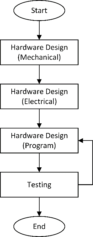
Figure 1. Flowchart of robot messenger system design 1
- Hardware Design and Implementation
- Hardware Specification Design
The design of Messenger Robot 1 using the "X" frame type has four omniwheels attached to the y-axis, 𝛼1 = 45°, 𝛼2 = 135°, 𝛼3 = 225°, 𝛼4 = 315°. The design of Messenger Robot 1 using the "X" frame type can be seen in Figure 2.
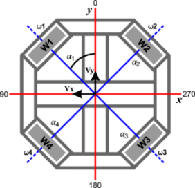
Figure 2. Design of robot coordinates
From the design of the robot coordinates, a 3-dimensional robot design is first made in accordance with the hardware made, so as to reduce the risk when making the robot. The 3-dimensional robot design can be seen in Figure 3 and Figure 4. The overall design of the robot is shown in Figure 4.
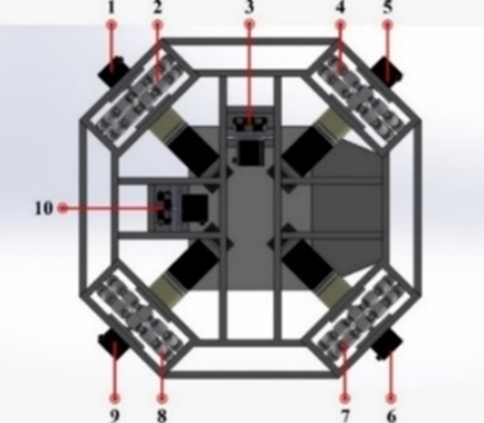
Figure 3. Design frame of robot base
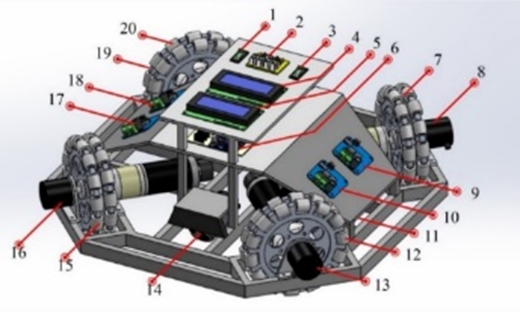
Figure 4. Overall design of the robot
Part descriptions of the components used in the robor are located in Table 1.
Table 1. Components used in the robot
No. | Information | No. | Information |
1 | Mini System switch | 11 | Wheel Free Wheel and Rotary Encoder coordinate Y |
2 | Keyboard | 12 | Omniwheel 1 |
3 | Motor Switches | 13 | Rotary Encoder External 1 |
4 | LCD RX (Master) | 14 | Wheel Free Wheel and Rotary Encoder coordinate X |
5 | TX LCD (Slave) | 15 | Omniwheel 2 |
6 | Robot mini system | 16 | Rotary Encoder External 2 |
7 | Omniwheel 4 | 17 | Motor Driver 2 |
8 | Rotary Encoder External 4 | 18 | Motor Driver 3 |
9 | Motor Driver 4 | 19 | Rotary Encoder External 3 |
10 | Motor Driver 1 | 20 | Omniwheel 3 |
The rotary encoder configuration is mounted on an omni wheel with an "X" shape frame with four wheels. Installation of rotary encoders on each omni wheel has the same distance from the center of the robot. So that the angle formed between the wheel axis against the y axis or the center point of the robot, the first wheel at an angle of 450, the second wheel at 1350, the third wheel on the 2250 axis, and the fourth wheel on the 3150 axis. The four rotary encoders are used to adjust the speed of each motor by reading the RPM value generated by each rotary encoder. In addition to placing a rotary encoder on each motor that is used to regulate the speed of the DC motor on each omni robot wheel, a rotary encoder is also installed at the x and y points of the robot which is called a rotary free wheel. Rotary free wheel is a rotary encoder sensor that functions to calculate the x and y coordinate values of the robot's center coordinates. The results of data reading from the rotary free wheel are then used in the omni robot odometry process in the process of moving forward. The installation of the two rotary encoders on the robot body is also useful for determining the distance traveled by the robot.
- Implementation of Hardware
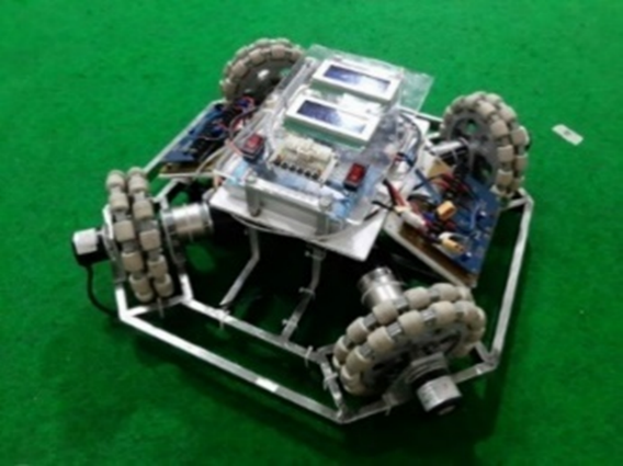
The physical part of the robot used for this research uses a 2 x 1 stainless steel frame with a thickness of 0.8 mm which is believed to be strong enough for the manufacture of Messenger Robot 1. An image of the physical part of the robot is located in Figure 5.
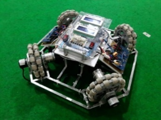
Figure 5. Physical parts of the robot
- Electronic System Design of Robot
- Schematic and Layout Design
The electronic design of the robot in this study uses two STM32F103C8T6 which are configured as slave and master. The STM32F103C8T6 slave is used to read the command button while the STM32F103C8T6 master is used as a six rotary encoder reader. The following electrical schematic can be seen in Figure 6. Then the robot electronics board looks like Figure 7.
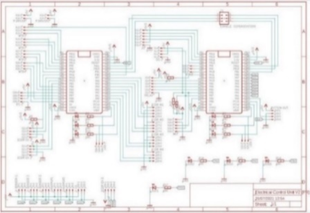
Figure 6. Electrical schematic
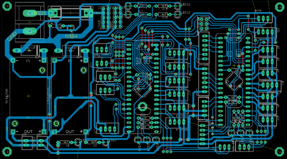
Figure 7. Robot electronics board
- Physical Implementation of the Electrical System
Part of the physical electrical system that is in accordance with the electrical system design that has been designed previously. The physical appearance of the electrical system can be seen in Figure 8.
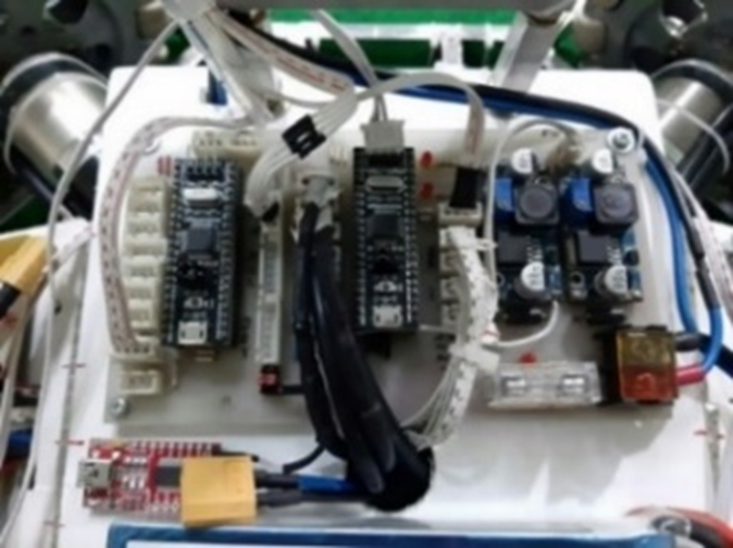
Figure 8. Physical electrical system
- Software Design
- Flowchart of How the System Works
Flowchart of how the robot system works as shown in Figure 9. In Figure 9 after the microcontroller initializes the program, then the robot enters standby mode, namely the robot mode is ready to run after that the keypad is pressed to run the program on the robot command to carry out the mission. If the keypad is not pressed, the robot remains in standby mode. The data that has been inputted will be processed by STM32F103 (master) to instruct the DC motor to move to rotate the omni wheel on the robot according to the predetermined RPM and then the external rotary encoder sensor reads the rotation of the free wheel until it reaches the target (x,y). If the robot cannot reach the predetermined target value (x,y), the DC motor rotates to move the robot to reach the predetermined target.
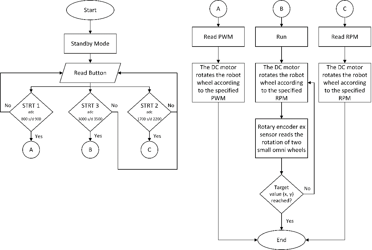
Figure 9. Flowchart of program
- PID Control Settings
Here is the program in the PID control setting. In Listing 1 there is an initialization for PID on each DC motor which is then fed back to the rotary encoder and processed every 100ms.
// Kp, Ki, Kd, pwm0 = pidmotor(0, setrpm1, 1.7, 0.085, 0.1, 255, 255);//Motor 1 pwm1 = pidmotor(1, setrpm2, 1.7, 0.085, 0.1, 255, 255);//Motor 2 pwm2 = pidmotor(2, setrpm3, 1.7, 0.085, 0.1, 255, 255);//Motor 3 pwm3 = pidmotor(3, setrpm4, 1.7, 0.085, 0.1, 255, 255);//Motor 4 |
Listing 1. PID settings
- Robot Motion System Design
The calculation of the distance traveled by the robot is the stage when the robot has counted the number of counters on the rotary encoder. The distance conversion formula is shown in Equation (1).
Based on Equation (1), the basis will be implemented in the programming language. The program shown on the Listing 2 of the process of calculating the distance traveled by the robot.
diameter[4] = 6; // diameter roda (cm) lubang[4] = 400; // jumlah pulsa dalam 1 putaran
diameter[5] = 6; // diameter roda (cm) lubang[5] = 400; // jumlah pulsa dalam 1 putaran void encoderex0(){ if (digitalRead(pinencoderexa[0]) == HIGH && digitalRead(pinencoderexb[0]) == HIGH) { pos[4]++; pos_rpm[4]++; } else { pos[4]--; pos_rpm[4]--; } hitung_jarak(4); panjang[4]=hitung[4]*pos[4]; // ubah ke satuan jarak tempuh (cm) } void encoderex1(){ if (digitalRead(pinencoderexa[1]) == HIGH && digitalRead(pinencoderexb[1]) == HIGH) { pos[5]++; pos_rpm[5]++; } else { pos[5]--; pos_rpm[5]--; } hitung_jarak(5); panjang[5]=hitung[5]*pos[5]; // hitung panjang fix } void hitung_jarak(int i) { { keliling[i] = PI * diameter[i]; hitung[i] = keliling[i] / lubang[i]; } |
Listing 1. Program to calculate distance
Robot positioning is done after getting a good and stable speed on the robot. The program shown on the Listing 3 explains the positioning of the robot.
void odometry() { if(button(0)==0) { counter=1; reset_stop(); lcd.clear(); lcd.setCursor(0,0); lcd.print("START"); delay(1000); } if(baca_odometer(5)<=-100&&counter==1) { lcd.clear(); set_motor(0, 0, 1); set_motor(1, 0, 1); set_motor(2, 0, 1); set_motor(3, 0, 1); while(1) { lcd.setCursor(0,3); lcd.print(baca_odometer(4)); lcd.setCursor(8,3); lcd.print(baca_odometer(5)); if(button(0)==0) break; while(Serial3.available()) { char c=Serial3.read(); if(isDigit(c)) in+=c; if(c=='a') {rx1=in.toInt(); in=""; } } } counter++; reset_stop(); lcd.clear(); lcd.setCursor(0,0); lcd.print(counter); delay(1000); } if(counter == 0 ){ setrpm1=0; setrpm2=0; setrpm3=0; setrpm4=0; } if(counter == 1 ){ setrpm1=-40; setrpm2=40; setrpm3=40; setrpm4=-40; } |
Listing 2. Robot positioning program cutout
After getting a good enough speed, the robot can determine the position coordinates with odometry. To estimate the position coordinates with respect to the initial axis, odometry is used. Rotary encoder is used as a detection of the number of turns of the wheel.
- RESULT AND DISCUSSION
In this study to find out how the workings of the Robot Messenger Robot 1 Motion Development at the 2019 ABU Indonesia Robot Contest Using the Odometry Method, so various ways of testing the robot are carried out to find out the system can function properly.
- Rotary Encoder Sensor Testing on Wheels
Testing of the rotary encoder sensor is done by reading the number of pulse signals generated from the rotation of each robot wheel. By rotating the wheels on the robot, it produces a pulse signal, so that the wheel rotation can be detected properly. For the results are shown in Table 2.
Table 2. The test results of reading the number of rotary encoder pulses
PWM | Rotary Encoder Wheel | Tachometer | Driver Output Voltage |
M1 | M2 | M3 | M4 | M1 | M2 | M3 | M4 | M1 | M2 | M3 | M4 |
Revolution per Minutes (RPM) | Volt |
40 | 112 | 97 | 84 | 60 | 111 | 97 | 83 | 59 | 396 | 3.7 | 3.3 | 2.6 |
60 | 176 | 163 | 147 | 125 | 176 | 162 | 145 | 125 | 6.24 | 6.06 | 5.45 | 4.75 |
80 | 231 | 214 | 196 | 174 | 230 | 212 | 194 | 174 | 7.93 | 7.74 | 7.3 | 6.51 |
100 | 267 | 249 | 232 | 214 | 266 | 247 | 232 | 212 | 9.04 | 8.89 | 8.5 | 7.8 |
120 | 288 | 274 | 259 | 244 | 285 | 272 | 257 | 244 | 9.84 | 9.73 | 9.4 | 8.87 |
150 | 313 | 300 | 286 | 280 | 310 | 298 | 284 | 278 | 10.62 | 10.59 | 10.33 | 9.98 |
180 | 328 | 317 | 310 | 304 | 328 | 314 | 308 | 304 | 11.13 | 11.14 | 11 | 10.78 |
200 | 336 | 322 | 315 | 315 | 333 | 322 | 315 | 314 | 11.37 | 11.41 | 11.3 | 11.17 |
225 | 343 | 333 | 325 | 325 | 343 | 333 | 325 | 325 | 11.62 | 11.68 | 11.59 | 11.51 |
255 | 360 | 348 | 342 | 345 | 357 | 346 | 342 | 344 | 12.14 | 12.16 | 12.16 | 12.14 |
Table 2 shows the results of testing the motor speed against the given PWM value, where the motor speed has a different value between each motor, so it needs good PID control and a system that can run the motor according to the expected setpoint, so that the same speed is obtained between each motor.
- PID Testing
PID control testing aims to obtain Kp, Ki, and Kd values that can have a fast rising time and also low oscillation. Good PID control is expected to maintain motor rotation speed without being affected by load and battery conditions. In this test, each motor is given PID control in order to maintain the motor rotational speed according to the specified setpoint. Setting Kp, Ki, Kd is done by Trial and Error method until getting stable results.
- Testing Tuning Constant KP= 2.7; KI= 0.085; KD= 0.1, Setpoint = 40
In this test using the manual trial and error method and using the target rpm value setting of 40. In this test using a proportional constant value of 2.7, an integral constant value of 0.085 and a derivative constant value of 0.1. Figure 10 is a graphical form of the results of PID control tunning, and the results are shown in Table 3.
From the results in Figure 10 and Table 3 of the KP Constant Tuning test = 2.7; KI = 0.085; KD = 0.1 results in poor speed responsiveness because the system has a fairly high overshoot of 15% from the set point. The oscillations that occur in motor 1 are 8 times, motor 2 are 7 times, motor 3 are 7 times and motor 4 are 7 times.
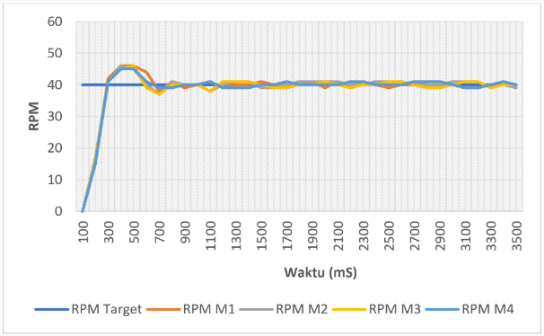

Figure 10. Results of Tunning Constants KP= 2.7; KI= 0.085; KD= 0.1
Table 3. Test Results with setpoint = 40, Kp = 2.7; KI = 0.085; KD = 0.1
Motor | Rise Time (tr) | Settling Time (ts) | Overshoot (%) | Steady State Error (SSE) |
1 | 300 ms | 900 ms | 15 % | ±1 |
2 | 300 ms | 800 ms | 15 % | ±1 |
3 | 250 ms | 1000 ms | 15 % | ±1 |
4 | 300 ms | 1100 ms | 12.5 % | ±1 |
- Testing Tuning Constants KP= 2; KI= 0.085; KD= 0.1
In this test using the manual trial and error method and using a target rpm value setting of 40. In this test using a proportional constant value of 2, an integral constant value of 0.085 and a derivative constant value of 0.1. Figure 11 is a graphical form of the results of tuning the PID control, and the results are shown in Table 4.
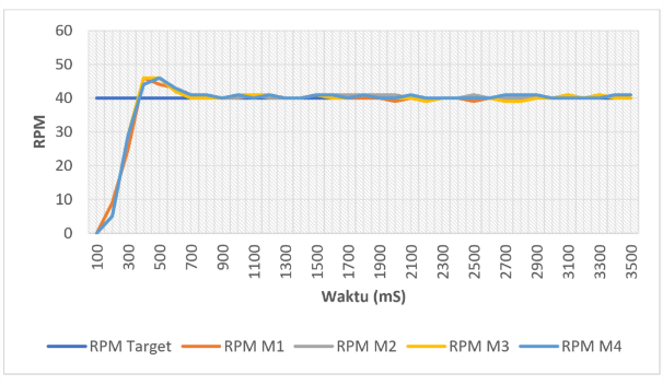

Figure 11. Result of KP Constant Tunning = 2; KI = 0.085; KD = 0.1
Table 4. Test results with setpoint = 40, KP = 2; KI = 0.085; KD = 0.1
Motor | Rise Time (tr) | Settling Time (ts) | Overshoot (%) | Steady State Error (SSE) |
1 | 400 ms | 1300 ms | 7.5 % | ±1 |
2 | 400 ms | 1250 ms | 10 % | ±1 |
3 | 400 ms | 1200 ms | 10 % | ±1 |
4 | 400 ms | 990 ms | 7.5 % | ±1 |
From the results of the KP = 2 constant tuning test; KI = 0.085; KD = 0.1 results in poor speed responsiveness because the system has a fairly high overshoot of 10% on motors 2 and 3 and 7.5% on motors 1 and 4 from the set point. The oscillations that occur on motor 1 are 5 times, motor 2 are 5 times, motor 3 are 7 times and motor 4 are 6 times.
- Testing Tuning Constant KP= 1.8; KI= 0.085; KD= 0.1, Setpoint = 40
In this test using the manual trial and error method and using the target rpm value setting of 40. In this test using a proportional constant value of 1.8, an integral constant value of 0.085 and a derivative constant value of 0.1. In Figure 12 is a graphical form of the results of PID control tunning, and the results are shown in Table 5.
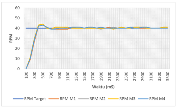

Figure 12. Result of Tunning Constant KP= 1.8; KI= 0.085; KD= 0.1
Table 5. Test results with setpoint = 40, KP = 1.8; KI = 0.085; KD = 0.1
Motor | Rise Time (tr) | Settling Time (ts) | Overshoot (%) | Steady State Error (SSE) |
1 | 400 ms | 1300 ms | 7.5 % | ±1 |
2 | 400 ms | 1190 ms | 10 % | ±1 |
3 | 400 ms | 1200 ms | 10 % | ±1 |
4 | 400 ms | 1100 ms | 7.5 % | ±1 |
From the results of the Tuning Test the KP Constant Tuning Test = 1.8; KI = 0.085; KD = 0.1 resulted in poor speed responsiveness because the system has a fairly high overshoot, namely 10% on motors 2 and 3 and 7.5% on motors 1 and 4 from the set point. The oscillations that occur in motor 1 are 5 times, motor 2 are 6 times, motor 3 are 3 times and motor 4 are 5 times.
- Testing Tuning Constant KP= 1.7; KI= 0.085; KD= 0.1, Setpoint = 40
In this test using the manual trial and error method and using a target rpm value setting of 40. In this test using a proportional constant value of 1.7, an integral constant value of 0.085 and a derivative constant value of 0.1. Figure 13 is a graphical form of the results of tuning the PID control, and the results are shown in Table 6.
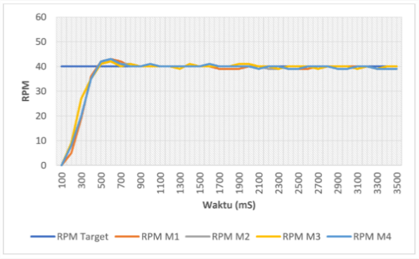

Figure 13. Result of Tunning Constant KP= 1.7; KI= 0.085; KD= 0.1
Table 6. Test results with setpoint = 40, KP = 1.7; KI = 0.085; KD = 0.1
Motor | Rise Time (tr) | Settling Time (ts) | Overshoot (%) | Steady State Error (SSE) |
1 | 460 ms | 800 ms. | 7.5 % | ±1 |
2 | 470 ms | 700 ms. | 5 % | ±1 |
3 | 470 ms | 860 ms. | 5 % | ±1 |
4 | 470 ms | 770 ms. | 5 % | ±1 |
From the test results of the KP Constant Tuning Test = 1.7; KI = 0.085; KD = 0.1 produces good speed responsiveness because the system has a good response on motor 1 as much as 7.5% on motors 2,3 and 4 as much as 7.5% of the set point. The oscillations that occur in motor 1 are 3 times, motor 2 are 5 times, motor 3 are 7 times and motor 4 are 4 times.
- Testing Tuning Constant KP= 1.6; KI= 0.085; KD= 0.1, Setpoint = 40
In this test using the manual trial and error method and using the target rpm value setting of 40. In this test using a proportional constant value of 1.6, an integral constant value of 0.085 and a derivative constant value of 0.1. In Figure 14 is a graphical form of the results of PID control tunning, and the results are shown in Table 7.
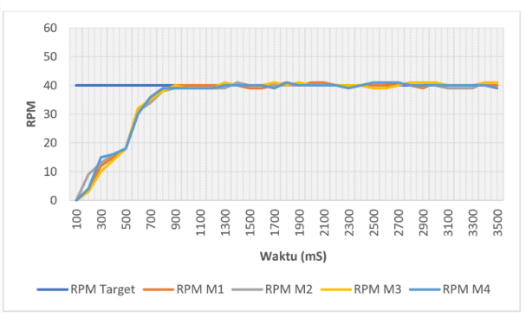

Figure 14. Result of Tunning Constant KP= 1.6; KI= 0.085; KD= 0.1
Table 7. Test results with setpoint = 40, KP = 1.6; KI = 0.085; KD = 0.1
Motor | Rise Time (tr) | Settling Time (ts) | Overshoot (%) | Steady State Error (SSE) |
1 | 870 ms | 900 ms | 2.5 % | ±1 |
2 | 1370 ms | 1450 ms | 2.5 % | ±1 |
3 | 880 ms | 1400 ms | 2.5 % | ±1 |
4 | 1250 ms | 1900 ms | 2.5 % | ±1 |
From the results of the Tuning Test the Tuning Test Constant KP = 1.6; KI = 0.085; KD = 0.1 results in poor speed responsiveness because it has a long response and does not reach the desired setpoint. the oscillations that occur in motor 1 are 6 times, motors 2, 3, 4 are 4 times.
- Robot Motion Testing
- Forward Robot Motion Testing
In forward motion testing, the robot is programmed to move straight ahead following the Y axis and can stop according to the specified target position. For the robot, markers are attached to the frame to mark the robot's navigational movements. This test uses an external rotary encoder sensor to calculate the distance traveled from the initial position to the target position, as shown in Figure 15, and the recap results of forward motion testing are shown in Table 8.
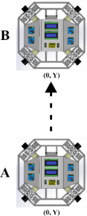
Figure 15. Illustration of Forward Robot Motion
Table 8. Recap results of forward motion testing
No | Target coordinates (cm) | Actual coordinates (cm) | Error (cm) |
X | Y | X | Y | X | Y |
1 | 0 | -100 | -0.33 | -103.48 | -0.33 | -3.48 |
2 | 0 | -100 | -0.05 | -100.70 | -0.05 | -0.70 |
3 | 0 | -100 | 0.19 | -102.16 | 0.19 | -2.16 |
4 | 0 | -100 | 0.94 | -101.79 | 0.94 | -1.79 |
5 | 0 | -100 | 0.145 | -101.41 | 0.145 | -1.41 |
Average | 0.179 | -1.908 |
The average error results obtained in the forward robot motion test are quite good, namely at the X coordinate point of 0.179 and at the Y coordinate of -1.908.
- Backward Robot Motion Testing
In testing the backward motion, the robot is programmed to move backwards following the Y axis and can stop according to the specified target position. For the robot, markers are attached to the frame to mark the robot's navigational movements. This test uses an external rotary encoder sensor to calculate the distance traveled from the initial position to the target position, as shown in Figure 16, and the recap results of backward motion testing are shown in Table 9.
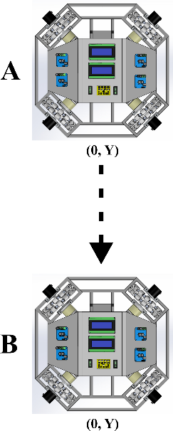
Figure 16. Illustration of backward robot motion
Table 9. Recap results of backward motion testing
No | Target coordinates (cm) | Actual coordinates (cm) | Error (cm) |
X | Y | X | Y | X | Y |
1 | 0 | 100 | -0.09 | 102.40 | -0.09 | 2.40 |
2 | 0 | 100 | 0.20 | 103.44 | 0.20 | 3.44 |
3 | 0 | 100 | 0.80 | 103.30 | 0.80 | 3.30 |
4 | 0 | 100 | 0.05 | 101.74 | 0.05 | 1.74 |
5 | 0 | 100 | 0.245 | 102.68 | 0.245 | 2.68 |
Average | 0.241 | 2.712 |
The average error results obtained in the forward robot motion test are quite good, namely at the X coordinate point of 0.241 cm and at the Y coordinate of 2.712 cm.
- Analysis of Testing
In testing the rotary encoder sensor on the wheel, the result is that this sensor can read the pulse value obtained in each rotation. Then from simple robot motion testing, namely forward and backward robot motion, the difference between the coordinates of the target to the actual target is still quite high on the X axis. In the PID tuning test which was carried out five times with different P constant values, the best results were obtained at fourth try. The fourth PID tuning experiment has resulted in a fast response and each motor can move stably. In the results of the robot motion test there are errors that are not recognized by the readings from the internal rotary encoder so that there is a difference in the actual distance to the target.
- CONCLUSION
From the tests that have been carried out on the Research Development of Robot Messenger Robot 1 Motion at the 2019 ABU Indonesia Robot Contest Using the Odometry Method, it can be concluded that, the first is the result of testing the rotational speed of a dc motor configured using a rotary encoder sensor can reach the specified setpoint, where in five trials with a setpoint of 40. The best response was obtained in the fourth experiment which resulted in a responsive and adaptive system with the fastest rise time value, the smallest overshoot value and a steady state error value close to the setpoint value and no oscillations occurred in the system. With a proportional constant value of 1.7, an integral constant value of 0.085 and a derivative constant value of 0.1. Second, the results of testing the odometry method using the rotary encoder sensor for simple motion, namely forward motion, obtained an average error at the X coordinate point of -0.58 cm and at the Y coordinate of -3.02 cm, while in backward motion the average the error is at the X coordinate of 0.39 cm and at the Y coordinate of 3.03 cm. Based on these results it can be concluded that the robot can move literally with a fairly good level of accuracy.
ACKNOWLEDGEMENT
Thank you to all who have been involved in this research. I hope this research can be useful for many people and hopefully in the future it can be further developed, because this research is far from perfect.
REFERENCES
[1] R. Hartono, T. N. Nizar, I. Robani, and D. A. Jatmiko, "Motion and Navigation Control System of a Mobile Robot as A Prototype of An Autonomous Vehicle," In IOP Conference Series: Materials Science and Engineering, vol. 879, no. 1, p. 012100, 2020, https://doi.org/10.1088/1757-899X/879/1/012100.
[2] A. Sofwan, H. R. Mulyana, H. Afrisal, and A. Goni, "Development of Omni-Wheeled Mobile Robot Based-on Inverse Kinematics and Odometry," 2019 6th International Conference on Information Technology, Computer and Electrical Engineering (ICITACEE), pp. 1-6, 2019, https://doi.org/10.1109/ICITACEE.2019.8904418.
[3] G. Popović et al., "Human localization in robotized warehouses based on stereo odometry and ground-marker fusion," Robotics and Computer-Integrated Manufacturing, vol. 73, p. 102241, 2022, https://doi.org/10.1016/j.rcim.2021.102241.
[4] X. Xiao et al., "Portable Body-Attached Positioning Mechanism Toward Robotic Needle Intervention," in IEEE/ASME Transactions on Mechatronics, vol. 25, no. 2, pp. 1105-1116, 2020, https://doi.org/10.1109/TMECH.2020.2974760.
[5] X. Jordens, R. Wilmart, E. Garone, M. Kinnaert, and L. Catoire, "A Project-Based Learning Approach for Building an Affordable Control Teaching Lab: The Centrifugal Ring Positioner," in IEEE Access, vol. 10, pp. 4907-4918, 2022, https://doi.org/10.1109/ACCESS.2022.3141588.
[6] J. Palacín and D. Martínez, "Improving the Angular Velocity Measured with a Low-Cost Magnetic Rotary Encoder Attached to a Brushed DC Motor by Compensating Magnet and Hall-Effect Sensor Misalignments," Sensors, vol. 21, no. 14, p. 4763, 2021, https://doi.org/10.3390/s21144763.
[7] F. Gao, H. Li, J. Fei, C. Lu, S. Guo, and J. Zhang, "Remote-control Real-time Video Interactive Robot," 2021 3rd International Academic Exchange Conference on Science and Technology Innovation (IAECST), pp. 40-43, 2021, https://doi.org/10.1109/IAECST54258.2021.9695720.
[8] K. Holdcroft, A. Bolotnikova, C. Belke, and J. Paik, "Modular robot networking: a novel schema and its performance assessment," 2022 IEEE/RSJ International Conference on Intelligent Robots and Systems (IROS), pp. 12698-12705, 2022, https://doi.org/10.1109/IROS47612.2022.9981688.
[9] D. Nemec, J. Andel, V. Simak, and R. Pirnik, "Safety Aspects of the Wheeled Mobile Robot," 2022 ELEKTRO (ELEKTRO), pp. 1-6, 2022, https://doi.org/10.1109/ELEKTRO53996.2022.9803409.
[10] H. Wang, N. Chen, D. Yang, and G. Fan, "Autonomous Navigation System for Indoor Mobile Robots Based on a Multi-sensor Fusion Technology," In CCF Conference on Computer Supported Cooperative Work and Social Computing, pp. 502-517, 2022, https://doi.org/10.1007/978-981-19-4546-5_39.
[11] P. I. -T. Chang, C. -C. Liu, S. -C. F. Chiang, and C. -Y. Lan, "Signal-based and Model-based Wheel Fault Detection of Omni-directional Vehicle with Mecanum Wheel," 2020 International Automatic Control Conference (CACS), pp. 1-6, 2020, https://doi.org/10.1109/CACS50047.2020.9289703.
[12] T. A. Mai, T. S. Dang, D. N. Anisimov, and E. Fedorova, "Fuzzy-PID Controller for Two Wheels Balancing Robot Based on STM32 Microcontroller," 2019 International Conference on Engineering Technologies and Computer Science (EnT), pp. 20-24, 2019, https://doi.org/10.1109/EnT.2019.00009.
[13] Y. Xia, Q. Li, R. Huang, and X. Zhao, "Design of Intelligent Medical Service Robot based on Raspberry Pi and STM32," 2022 IEEE 10th Joint International Information Technology and Artificial Intelligence Conference (ITAIC), pp. 1577-1581, 2022, https://doi.org/10.1109/ITAIC54216.2022.9836515.
[14] J. Wang, M. Li, W. Jiang, Y. Huang, and R. Lin, "A Design of FPGA-Based Neural Network PID Controller for Motion Control System," Sensors, vol. 22, no. 3, p. 889, 2022, https://doi.org/10.3390/s22030889.
[15] L. Li, H. Hu, Y. Qin, and K. Tang, "Digital approach to rotational speed measurement using an electrostatic sensor," Sensors, vol. 19, no. 11, p. 2540, 2019, https://doi.org/10.3390/s19112540.
[16] C. Zhao and Z. Hua, "Design of Motor Speed Control System Based on STM32 Microcontroller," 2022 International Conference on Computation, Big-Data and Engineering (ICCBE), pp. 274-276, 2022, https://doi.org/10.1109/ICCBE56101.2022.9888225.
[17] A. Badimon et al., "Negative feedback control of neuronal activity by microglia," Nature, vol. 586, no. 7829, pp. 417-423, 2020, https://doi.org/10.1038/s41586-020-2777-8.
[18] A. Latif, K. Shankar, and P. T. Nguyen, "Legged fire fighter robot movement using PID," Journal of Robotics and Control (JRC), vol. 1, no. 1, pp. 15-19, 2020, https://doi.org/10.18196/jrc.1104.
[19] D. Babunski, J. Berisha, E. Zaev, and X. Bajrami, "Application of Fuzzy Logic and PID Controller for Mobile Robot Navigation," 2020 9th Mediterranean Conference on Embedded Computing (MECO), pp. 1-4, 2020, https://doi.org/10.1109/MECO49872.2020.9134317.
[20] D. U. Rijalusalam and I. Iswanto, "Implementation kinematics modeling and odometry of four omni wheel mobile robot on the trajectory planning and motion control based microcontroller," Journal of Robotics and Control (JRC), vol. 2, no. 5, pp. 448-455, 2021, https://doi.org/10.18196/jrc.25121.
AUTHOR BIOGRAPHY

| Dody Kurniawan is a student at Department of Electrical Engineering, Faculty of Industrial Technology, Universitas Ahmad Dahlan, Yogyakarta, Indonesia.
|
|
|

| Ir. Wahyu Sapto Aji, S.T., M.T., IPM is a Lecturer in the Department of Electrical Engineering, Faculty of Industrial Technology, Universitas Ahmad Dahlan, Yogyakarta, Indonesia.
|
|
|
Motion-Making Messenger Robot 1 at the Abu Indonesia Robot Contest 2019 Using the Odometry Method (Dody Kurniawan)