ISSN: 2685-9572 Buletin Ilmiah Sarjana Teknik Elektro
Vol. 8, No. 5, October 2026, pp. 1529-1543
Coordinated Resistive Superconducting Fault Current Limiting for Transmission-Line Current Differential Protection
Habib Muhammad Usman, Marif Daula Siddique, Mohammed Madhat Abualnaeem,
Forsan Hamoud Abdulmola Hassan, Ahmed Ali Elnour Mahmoud, Abdulrahman Al-Hashedi
Department of Electrical Engineering, King Fahd University of Petroleum and Minerals (KFUPM), Dhahran,
Saudi Arabia
ARTICLE INFORMATION |
| ABSTRACT |
Article History: Received 20 June 2026 Revised 24 August 2026 Accepted 19 October 2026 |
| 
High-resistance internal faults remain a challenging operating condition for transmission-line current differential protection because the resulting differential current may approach the relay sensitivity boundary, whereas severe through-current conditions impose stringent security requirements. This paper proposes a coordinated protection framework that integrates a resistive superconducting fault current limiter (R-SFCL) with current differential protection and evaluates the R-SFCL not only in terms of fault-current suppression, but also through its influence on the differential–restraint operating margin and high-resistance fault detectability. The proposed method couples an electrothermal R-SFCL model with synchronized terminal-current phasors and a deterministic search for the maximum detectable fault resistance. The protection performance is systematically evaluated for internal three-phase (ABC), three-phase-to-ground (ABG), phase-to-phase (AB), and single-phase-to-ground (AG) faults over aggregate R-SFCL resistances ranging from 5 to 100 Ω. Simulation results show that the R-SFCL reduces peak fault current by 31.0–41.3% while preserving dependable operation of the differential relay for all investigated internal faults under a 200-A pickup threshold and a 0.75 differential-restraint characteristic. Increasing the R-SFCL resistance also enhances high-resistance fault sensitivity. At 20 Ω, the maximum detectable fault resistances are 90, 89, 73, and 80 Ω for ABC, ABG, AB, and AG faults, respectively, increasing to limiting values of 90, 92, 73, and 83 Ω at 30 Ω or above. No further sensitivity improvement is observed beyond 30 Ω for any fault category, revealing a clear saturation in the protection benefit. These results identify an effective coordination region of 20–30 Ω, within which substantial fault-current limitation is achieved while retaining most of the attainable improvement in differential-protection sensitivity. The proposed framework therefore provides a quantitative basis for protection-aware R-SFCL sizing that balances fault-current mitigation, relay dependability, and high-resistance fault sensitivity. |
Keywords: R-SFCL; Current Differential Protection; Transmission-Line Protection; Fault-Current Limitation; High-Resistance Fault |
Corresponding Author: Habib Muhammad Usman, Department of Electrical Engineering, King Fahd University of Petroleum and Minerals (KFUPM), Dhahran, Saudi Arabia. Email: habibusman015@gmail.com |
This work is open access under a Creative Commons Attribution-Share Alike 4.0 
|
Document Citation: H. M. Usman, M. D. Siddique, M. M. Abualnaeem, F. H. A. Hassan, A. A. E. Mahmoud, and A. Al-Hashedi, “Coordinated Resistive Superconducting Fault Current Limiting for Transmission-Line Current Differential Protection,” Buletin Ilmiah Sarjana Teknik Elektro, vol. 8, no. 5, pp. 1529-1543, 2026, DOI: 10.12928/biste.v8i5.17142. |
INTRODUCTION
Transmission-line protection is a primary layer of power-system security because internal faults must be isolated before thermal, electrodynamic, voltage, and stability consequences spread to adjacent equipment. Current differential protection compares synchronized currents entering a defined zone and is therefore inherently selective: the corrected terminal currents nearly cancel during normal loading and external faults, whereas an internal fault produces a nonzero operating current [1]–[3]. Practical performance is governed by both dependability for internal faults and security during through faults, current-transformer (CT) error, waveform distortion, communication delay, and time-synchronization mismatch [4]. High-resistance internal faults are critical because they reduce the differential operating quantity toward the relay boundary, while low-impedance close-in faults can impose severe current stress on CTs and circuit breakers [5].
The protection problem is increasingly important in networks with high short circuit capacity and low equivalent impedance. A low impedance grid can produce severe close in fault currents that increase the duty imposed on circuit breakers and current transformers [6]. At the same time, a high resistance fault can be difficult to detect because the resulting current is small and may not clearly separate from load or restraint quantities [7]. Recent work on renewable and storage connected lines shows that phasor quality and data reliability remain important for differential protection when converter dominated sources are present [8]. Robust communication and cyber physical security are also increasingly relevant because current differential relays depend on remote terminal data [9].
Superconducting fault current limiters introduce negligible impedance in normal operation and rapidly develop limiting impedance after a quench. Resistive SFCLs are particularly suitable for series insertion because the limiting mechanism is direct and scalable through series-parallel module design [10]–[18]. Their behavior depends on the superconducting layer, stabilizer, shunt path, thermal capacity, cooling boundary, and recovery process; consequently, a network-level post-quench resistance must be interpreted as an aggregate modular parameter rather than the resistance of a single coated-conductor tape [19]–[23]. Recent work also shows that shunt resistance and cooling design materially affect limitation and recovery [38],[52].
Series current-limiting devices can change the quantities used by protection functions. Published studies have reported effects on incremental-frequency, distance, overcurrent, and differential protection [24]–[27], [36][37]. The relevant question is therefore not whether an R-SFCL reduces current, but whether its resistance is coordinated with relay pickup and restraint settings. This distinction is especially important in modern networks where converter-interfaced sources, abnormal samples, synchronization error, and communication latency can already challenge conventional differential protection [53]–[59].
The research gap is the limited traceable analysis of how the complete R-SFCL resistance sweep changes the operating margin and maximum detectable fault resistance of a transmission-line current differential relay. Prior studies often emphasize current reduction or report selected operating points, whereas protection engineering requires a transparent mapping among limiter resistance, differential current, restraint current, pickup margin, and sensitivity limit [36][37].
The research contribution is threefold. First, the study provides a reproducible framework connecting R-SFCL electrothermal behavior, aggregate post-quench resistance, synchronized terminal-current phasors, and the two-condition differential trip boundary. Second, it reports the complete 5–100 Ω sweep and uses maximum detectable fault resistance, percentage improvement, and marginal gain as traceable sensitivity indices for ABC, ABG, AB, and AG faults. Third, it identifies where additional R-SFCL resistance ceases to improve sensitivity and separates this protection optimum from the independent objective of fault-current suppression. The remainder of the paper presents the model and assumptions, the deterministic sensitivity search, quantitative robustness considerations, results, comparison with recent intelligent protection methods, limitations, and conclusions.
- METHODS
Research Design and Simulation Workflow
This study uses a deterministic MATLAB/Simulink comparative design. Identical source, line, fault, and relay settings are simulated without and with the R-SFCL so that changes in relay response can be attributed to the limiter. For each fault type and limiter resistance, the fault resistance is increased until one of the trip conditions is no longer satisfied. The highest fault resistance that still produces a trip is recorded as the sensitivity limit. Performance is evaluated using the absolute increase in this limit, percentage gain, marginal gain between successive limiter settings, and the variation observed across the complete resistance sweep.
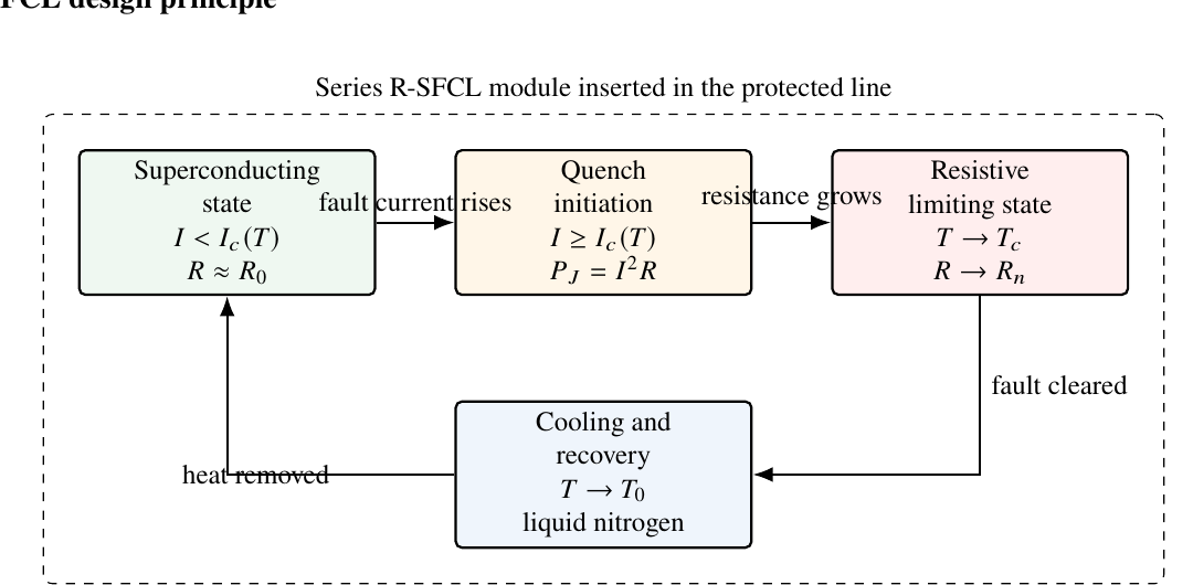
The workflow contains five stages. The first stage defines the two source transmission network and line parameters. The second stage inserts the R-SFCL as a modular post quench resistance supported by the electrothermal model. The third stage applies ABC, ABG, AB, and AG internal faults while varying fault resistance. The fourth stage extracts fundamental current phasors at both line terminals. The fifth stage evaluates the differential current, restraint current, practical ratio, and trip condition. Figure 1 presents R-SFCL operating diagram. Figure 2 gives the flowchart used to calculate the maximum detectable fault resistance. Figure 3 shows the simulation architecture.
R-SFCL Design Principle
The R-SFCL is placed in series near terminal M of the protected line as depicted in Figure 1. Under normal operation, the current remains lower than the temperature dependent critical current and the device has negligible resistance [38]. During a fault, heat generated inside the superconducting element drives a quench and increases the equivalent resistance [39]. After fault clearing, heat exchange with the liquid nitrogen bath supports recovery toward the superconducting state [40]. The model therefore represents the limiter as a low resistance branch before quench and as an aggregate post quench resistance during fault current limitation.
Figure 1. Technical operating cycle of the resistive superconducting fault current limiter used in the protection study
Electrical Thermal Model of the R-SFCL
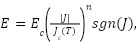
The nonlinear electrical behavior of the superconducting layer is represented using a power law relation, which is commonly used for coated conductor over current analysis [21]. The electric field  in the superconducting layer is
| 
| (1) |
Where  is the critical electric field criterion, J is the current density,
 is the temperature dependent critical current density,
 is conductor temperature, and n is the power law exponent.
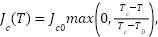
The temperature dependent critical current density is approximated as
| 
| (2) |
Where  is the critical current density at coolant temperature
 , and
 is the critical temperature. This expression captures the reduction of superconducting capability as temperature approaches [11].
The instantaneous resistance of the superconducting layer is obtained from the field-current relation as
| 
| (3) |
Where  is the active conductor length and
 is the equivalent cross sectional area. A metallic shunt or stabilizer layer is included to share current and reduce localized heating, which is consistent with practical R-SFCL designs [41]. The equivalent module resistance is
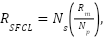
Where  is the shunt resistance. The network level limiter resistance is
| 
| (5) |
Where  and
 are the equivalent numbers of series and parallel modules. Equation (5) justifies the use of 5, 10, 20, 30, 50, and 100 Ω as aggregate R-SFCL values rather than single tape resistance values [14][15].
The investigated 5, 10, 20, 30, 50, and 100 Ω values span three engineering regions: a low-resistance region in which the limiter moderately changes the fault current (5–10 Ω), a coordination region in which relay sensitivity changes rapidly (20–30 Ω), and a high-resistance region used to examine whether further resistance provides additional protection benefit (50–100 Ω). The broad range is consistent with aggregate modular R-SFCL design, while the intermediate values allow the saturation point to be identified from the marginal sensitivity gain [14]–[16],[38].
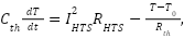
The lumped thermal balance is written as
| 
| (6) |
Where  is the equivalent thermal capacitance, IHTS is the superconducting layer current, and Rth is the thermal resistance to the coolant. The first term in Equation (6) represents Joule heating, while the second term represents cooling. Thermal electrical analogy models support this type of lumped representation for SFCL transient simulation [20]. Delayed current zeros and current limiting behavior in industrial systems also depend on this electrical thermal interaction [42].
Current Differential Relay Model
The current differential relay monitors the terminal currents of the protected line. The instantaneous terminal currents are denoted by  and
 , with positive polarity into the protected zone. During an internal fault, both terminal currents feed the fault and the algebraic sum becomes non zero. During normal operation or an external through fault, the terminal currents approximately cancel after polarity correction. This principle follows Kirchhoff current law and is the basis of line differential protection [43].
Let  and
 denote the fundamental phasors extracted from and . The differential current is
| 
| (7) |
where  is the relay operating current. The restraint current is defined as
| 
| (8) |
where  represents the through current related restraint quantity. The practical differential-restraint ratio is
| 
| (9) |
where ε is a small positive number used only to avoid division by zero in numerical evaluation.
The relay issues a trip when two conditions are simultaneously satisfied:
| 
| (10) |
| 
| (11) |
In this study, the pickup current is  = 200 A and the restraint coefficient is
 = 0.75. The pickup is intentionally well below the smallest reported internal-fault differential operating quantity while remaining above the numerical prefault mismatch of the synchronized model. The 0.75 restraint coefficient imposes a conservative percentage-differential boundary during large through-current conditions. These values are fixed for every case so that the effect of R-SFCL resistance is not confounded by adaptive setting changes. They are study settings, not universal relay recommendations; field application requires coordination with CT class, charging-current compensation, communication performance, and the manufacturer’s characteristic [53],[55].
Fault Current Formulation
Symmetrical components are used to represent unbalanced faults because ABC, ABG, AB, and AG faults do not all excite the same sequence networks. Fortescue’s transformation decomposes phase quantities into positive, negative, and zero sequence components [44]. For an AG fault, the boundary conditions are
| 
| (12) |
where  is the fault resistance in sequence form, the AG fault current satisfies
| 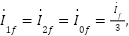
| (13) |
where  ,
 , and
 are the positive, negative, and zero sequence fault currents.
If  and
 are the positive sequence impedances from the fault point to terminals M and N, and
 and
 are the zero sequence impedances, the sequence fault current can be written as
| 
| (14) |
where  ,
 , and
 are the sequence voltages at the fault point, and ∥ denotes parallel impedance. Equation (14) shows that RSFCL changes the current distribution and therefore modifies the relay quantities.
The terminal current contribution from terminal M is represented by
| 
| (15) |
while the terminal N contribution is
| 
| (16) |
Here  is the pre fault line current. The positive and zero sequence current distribution factors are
| 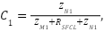
| (17) |
| 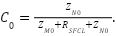
| (18) |
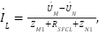
The pre fault load current is estimated from
| 
| (19) |
where  and
 are the terminal voltages. These equations clarify how the
 changes both the fault current and the terminal current balance used by the relay.
System Parameters and Measurement Settings
The simulated line uses the parameters summarized in Table 1. The two sources are rated at 230 kV and have phase angles of zero degrees and 20 degrees. The source resistance and inductance are included so that short circuit currents are not idealized. The 100 km line is represented using positive and zero sequence parameters, which are required for balanced and unbalanced fault studies [2].
Table 1. Transmission line and source parameters used in the simulation
Parameter | Value | Unit |
Rated frequency | 50 | Hz |
Source per-phase resistance | 0.8929 | Ω |
Source per-phase inductance | 32.58 ×  | H |
Source line voltage | 230 | kV |
Source phase angles | 0 and 20 | degree |
Protected line length | 100 | km |
Positive sequence resistance | 0.01273 | Ω/km |
Zero sequence resistance | 0.3864 | Ω/km |
Positive sequence inductance | 0.9337 × | H/km |
Zero sequence inductance | 4.1264 × | H/km |
Positive sequence capacitance | 12.74 ×  | F/km |
Zero sequence capacitance | 7.751 × | F/km |
Source positive/negative-sequence resistance | 0.8929 | Ω |
Source positive/negative-sequence inductance | 32.58 × | H |
Source zero-sequence resistance (model assumption) | 0.8929 | Ω |
Source zero-sequence inductance (model assumption) | 32.58 × | H |
Relay sampling frequency | 10 | kHz |
Samples per 50 Hz cycle | 200 | samples |
The relay uses a 10 kHz sampling frequency and a one-cycle 50 Hz phasor-estimation window, corresponding to 200 samples per cycle. This sampling rate provides sufficient resolution for the transient response while supporting stable extraction of the fundamental current component. The source is represented by a balanced, grounded three-phase Thevenin equivalent. The same per-phase resistance and inductance are used for the positive-, negative-, and zero-sequence source networks, as listed in Table 1. Consequently, the results are most directly applicable to systems with comparable source sequence impedances; networks with substantially different zero-sequence source characteristics should be assessed using their measured parameters.
The maximum detectable fault resistance is obtained using the procedure in Figure 2. For each fault type and R-SFCL resistance, the fault resistance is increased until either (10) or (11) is no longer satisfied. The preceding value is retained as the sensitivity limit. Since each setting represents a deterministic simulation case, the protection benefit is expressed through absolute and percentage changes in the sensitivity limit and through the marginal gain between successive limiter resistances.
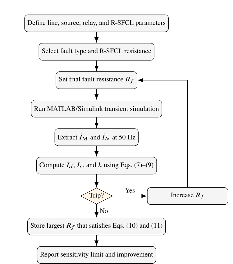
Figure 2. Flowchart used to calculate the maximum detectable fault resistance for each fault type and R-SFCL resistance
Relay Implementation and Practical Limitations
The relay processes one 20 ms cycle of current samples from each line terminal. At the 10 kHz sampling rate, this corresponds to 200 samples per terminal. These samples are used to estimate the 50 Hz current phasors, after which the differential current, restraint current, and trip decision are calculated directly from (7) to (11). The required processing is modest for a numerical relay because only two short sample windows and a small number of direct calculations are involved. The dominant operating delay is therefore the one-cycle measurement window rather than the calculation itself. Accordingly, the scheme is intended for dependable current differential protection and not for sub-millisecond travelling-wave protection.
Practical differential protection is sensitive to errors in terminal-current measurement and time alignment [53]. At 50 Hz, a synchronization error of 100 μs introduces about 1.8° phase displacement, while a 1 ms error introduces about 18° [54]. CT ratio error creates a proportional current mismatch, and CT saturation produces additional magnitude and phase distortion during heavy external faults [55]. Communication delay does not affect the comparison when both terminal measurements carry accurate timestamps and are aligned before calculation; unequal delay, packet loss, or incorrect timestamps can create a false differential quantity [56]. Practical implementation should therefore include CT-saturation supervision, suitable restraint during severe through faults, data-quality and packet-loss checks, and continuous monitoring of time synchronization [55]. The simulations assume correctly scaled CT signals and synchronized communication. The reported results therefore quantify internal-fault sensitivity for the stated model and settings; external-fault security under CT saturation, communication disturbances, and measurement noise requires separate validation.
Relay Principle and Network Diagrams
Figure 3 illustrates the operating principle of current differential protection. With terminal-current polarities directed into the protected zone, the corrected currents cancel during normal loading and external faults but add during an internal fault. Figure 4 shows the two-terminal transmission line, the location of the R-SFCL near terminal M, the terminal current measurements, and the internal fault point. Together, the diagrams define the protected zone and the measurement locations used in the simulation.
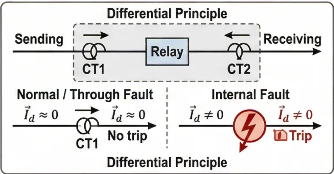
Figure 3. Current differential relay principle for the protected transmission line
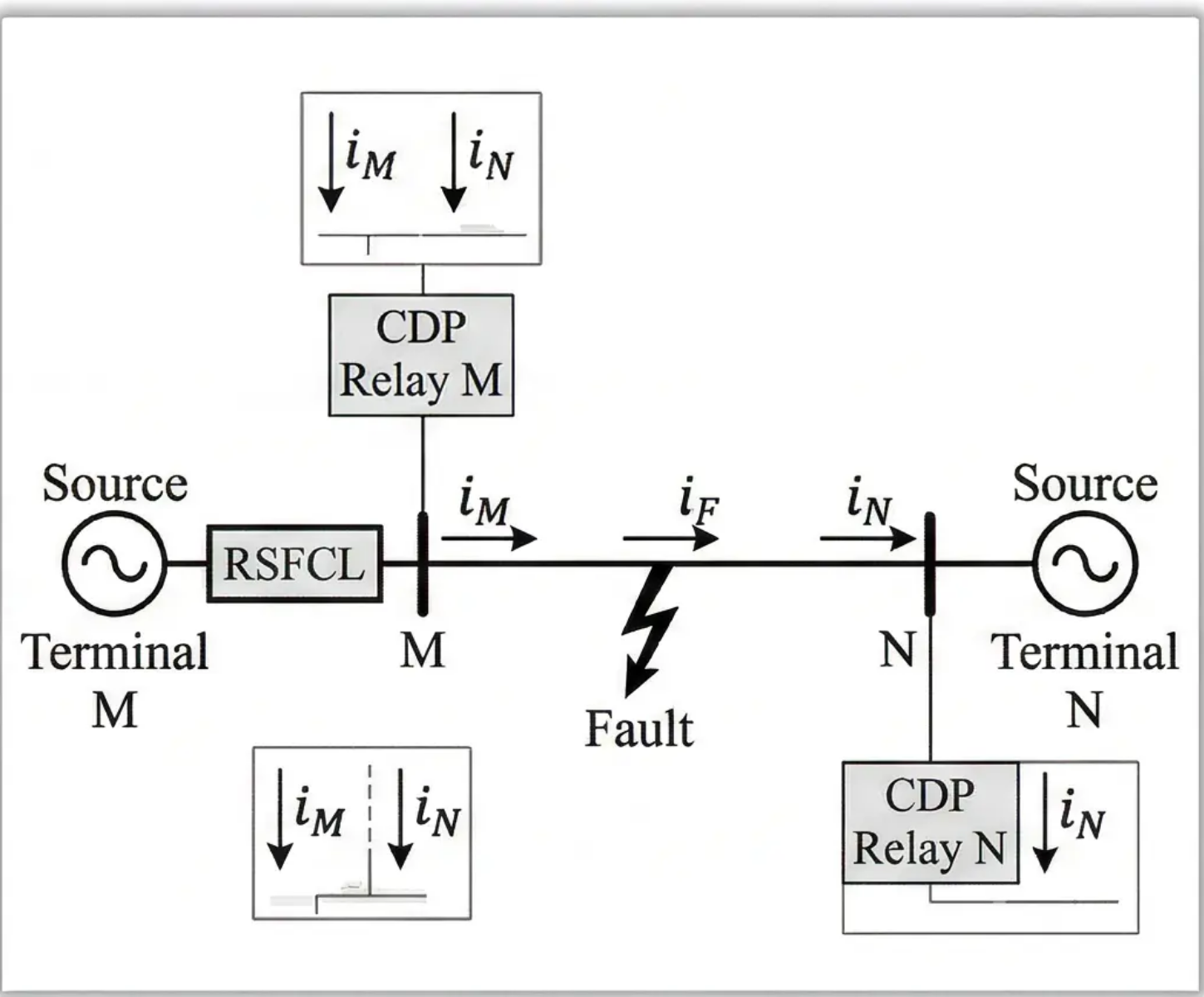
Figure 4. Two terminal transmission line model with terminal sources, R-SFCL location, relay measurements, and internal fault point
RESULTS AND DISCUSSION
Sensitivity Improvement Under Different Fault Types
Table 2 summarizes the maximum detectable fault resistance for ABC, ABG, AB, and AG faults. The no-limiter reference is constant for each fault type because it is evaluated using the same line and relay settings. The R-SFCL case changes with limiter resistance because the post quench resistance modifies the terminal current distribution and the differential-restraint ratio.
The sensitivity gain depends on the selected limiter resistance (Table 3). At 5 Ω, the improvements are 3.8%, 5.2%, 3.1%, and 7.1% for ABC, ABG, AB, and AG faults, respectively. At 10 Ω, the gains increase to 7.7%, 9.1%, 9.2%, and 10.0%, and at 20 Ω they reach 15.4%, 15.6%, 12.3%, and 14.3%. The highest values within the investigated range are 15.4% for ABC, 19.5% for ABG, 12.3% for AB, and 18.6% for AG. These maxima are reached at 20 Ω for ABC and AB faults and at 30 Ω for ABG and AG faults. Thus, the final improvement for each fault type applies only after its corresponding threshold resistance has been reached.
Marginal gain was calculated from the change in the maximum detectable fault resistance between successive R-SFCL settings. For ABC and AB faults, no further increase in sensitivity occurs above 20 Ω. For ABG and AG faults, increasing the limiter from 20 to 30 Ω adds 3 Ω to the detectable fault-resistance limit, whereas the 30–50 Ω and 50–100 Ω increments produce no additional gain. Thus, every fault type reaches a nearly constant sensitivity level once the SFCL resistance reaches 30 Ω, indicating that further increases in resistance provide negligible additional improvement in protection sensitivity. Across the six investigated resistance settings, the average sensitivity enhancements are 12.18% for ABC faults, 14.72% for ABG faults, 10.26% for AB faults, and 14.52% for AG faults, with corresponding standard deviations of 5.11%, 6.18%, 3.73%, and 4.98%, respectively. The standard deviation quantifies the variability of the sensitivity improvement across the tested SFCL resistance values. A relatively small standard deviation indicates that the improvement remains consistent and stable over the investigated resistance range, whereas a larger standard deviation reflects a stronger dependence of relay sensitivity on the selected SFCL resistance. Therefore, the obtained standard deviations confirm that, despite minor variations among fault categories, the proposed protection scheme delivers a robust and repeatable enhancement in sensitivity, with the improvement becoming increasingly stable as the SFCL resistance approaches its optimal operating region.
Table 2. Maximum detectable fault resistance for all investigated internal faults.
RSFCL (Ω) | ABC (Ω) | ABG (Ω) | AB (Ω) | AG (Ω) |
Without | With | Without | With | Without | With | Without | With |
5 | 78 | 81 | 77 | 81 | 65 | 67 | 70 | 75 |
10 | 78 | 84 | 77 | 84 | 65 | 71 | 70 | 77 |
20 | 78 | 90 | 77 | 89 | 65 | 73 | 70 | 80 |
30 | 78 | 90 | 77 | 92 | 65 | 73 | 70 | 83 |
50 | 78 | 90 | 77 | 92 | 65 | 73 | 70 | 83 |
100 | 78 | 90 | 77 | 92 | 65 | 73 | 70 | 83 |
Table 3. Percentage sensitivity improvement and marginal-gain interpretation across the complete R-SFCL sweep
R-SFCL (Ω) | ABC gain (%) | ABG gain (%) | AB gain (%) | AG gain (%) | Marginal interpretation |
5 | 3.8 | 5.2 | 3.1 | 7.1 | Initial benefit |
10 | 7.7 | 9.1 | 9.2 | 10.0 | Increasing benefit |
20 | 15.4 | 15.6 | 12.3 | 14.3 | ABC/AB saturation reached |
30 | 15.4 | 19.5 | 12.3 | 18.6 | ABG/AG saturation reached |
50 | 15.4 | 19.5 | 12.3 | 18.6 | Zero marginal gain |
100 | 15.4 | 19.5 | 12.3 | 18.6 | Zero marginal gain |
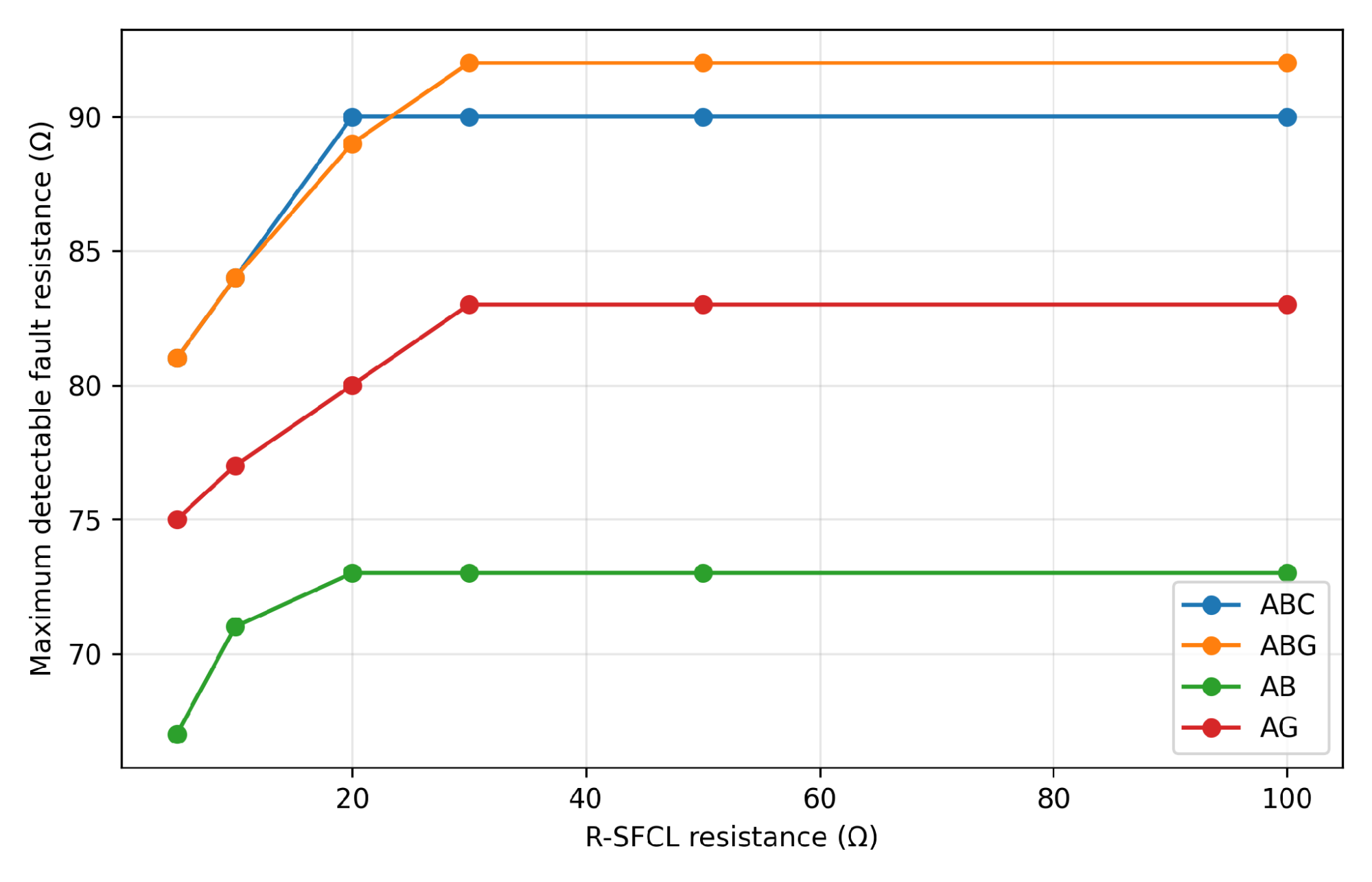
Figure 5. Maximum detectable fault resistance as a function of equivalent R-SFCL resistance
Graphical Sensitivity Results
Figure 6 provides a waveform-based view of the relay sensitivity under low-impedance and high-resistance fault conditions. The first three cases, shown in Figure 6(a) to Figure 6(c), represent low-impedance ABC, AB, and AG faults, respectively. In these cases, the fault current is sufficiently high, and the relay operating quantity remains clearly distinguishable from the prefault condition. This indicates that low-impedance faults are not the most critical operating condition for the current differential relay, because the differential current can easily exceed the relay pickup setting. In Figure 6(a), the ABC low-impedance fault produces a balanced three-phase response. Since the fault involves all phases, the relay receives strong current contribution from both line terminals. This makes the internal fault condition easy to identify. Similarly, Figure 6(b) shows that the AB low-impedance fault still produces a clear disturbance in the affected phases, although the response is lower than the three-phase case because the zero-sequence path is not involved.
In Figure 6(c), the AG fault response includes the ground-return path, and the waveform confirms that the relay remains sensitive to single-line-to-ground faults when the fault resistance is low. The last three cases in Figure 6(d) to Figure 6(f) show the more demanding ABC fault conditions with increasing fault resistance. When the fault resistance is increased to 20 ohms in Figure 6(d), the post-fault waveform is still clearly visible, and the relay has sufficient operating margin. However, as the resistance increases to 50 ohms in Figure 6(e), the post-fault current magnitude becomes smaller, and the fault signature becomes less pronounced. This reduction is expected because a higher fault resistance limits the fault current and weakens the differential quantity available to the relay. The most severe case is shown in Figure 6(f), where the ABC fault resistance is 100 ohms. In this case, the waveform amplitude is much closer to the pre-fault level, meaning that the relay operates near its sensitivity boundary. This is the region where the R-SFCL becomes most useful. The limiter does not simply reduce the current; it changes the current distribution between the two-line terminals and improves the differential-restraint relationship. Therefore, the graphical results in Figure 6 confirm the numerical sensitivity results reported in Table 2. The R-SFCL provides limited additional value when the fault is already easy to detect, but it becomes more valuable when the fault resistance increases and the relay approaches its operating boundary.
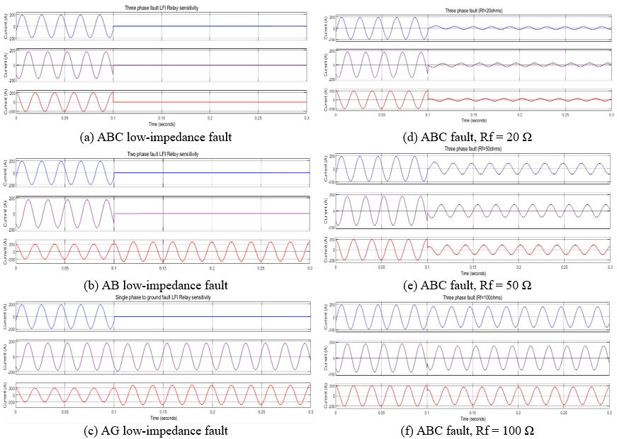
Figure 6. Grouped sensitivity plots for low impedance and high resistance fault cases
Fault Current Suppression Without and with R-SFCL
Figure 7 shows the time-domain fault current responses when the R-SFCL is not installed. In all four cases, the fault produces a sharp increase in current magnitude immediately after fault inception. The ABC fault in Figure 7(a) gives the highest current, reaching approximately 3750 A. This is expected because a three-phase fault is a balanced short-circuit condition and normally produces the largest current contribution from the source network. Such a high current level can impose severe electrodynamic and thermal stress on line conductors, current transformers, circuit breakers, and other primary equipment.
For the ABG fault shown in Figure 7(b), the peak current reaches approximately 3249 A. This value is lower than the ABC case but still severe because the fault includes both phase-to-phase and ground-return components. The AB fault in Figure 7(c) reaches approximately 3197 A. Since this fault does not involve the zero-sequence network, its current path differs from the ground fault cases, but the current magnitude remains high enough to stress protection and switching equipment. The AG fault in Figure 7(d) produces a lower peak current of approximately 2900 A, which is consistent with the additional impedance introduced by the ground-return path. The corresponding responses with the R-SFCL are shown in Figure 8. The effect of the limiter is immediately visible in all cases. In Figure 8(a), the ABC fault current is reduced from approximately 3750 A to 2200 A after limiting. This corresponds to a reduction of about 41.3%. The ABG response in Figure 8(b) decreases from 3249 A to 2183 A, giving a reduction of about 32.8%. In Figure 8(c), the AB fault current decreases from 3197 A to 2160 A, corresponding to a reduction of about 32.4%. For the AG fault in Figure 8(d), the current decreases from 2900 A to 2000 A, giving a reduction of about 31.0%.
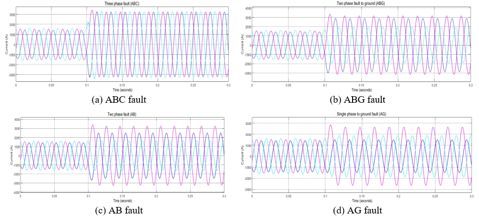
Figure 7. Time domain fault current responses without the R-SFCL
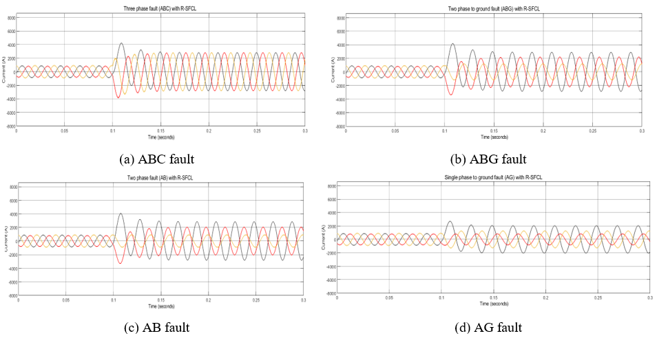
Figure 8. Time domain fault current responses with the R-SFCL
These reductions are important because electrodynamic force increases approximately with the square of current, while thermal stress depends on the energy released during the fault. A reduction of at least 31% in peak current therefore lowers both mechanical and thermal duty before circuit-breaker interruption. Relay coordination was preserved: every reported internal-fault case satisfied the 200 A pickup and restraint conditions in (10) and (11) after limiting. The R-SFCL thus reduced fault-current stress without preventing identification of faults within the protected zone.
Comparative Relay Performance
Table 4 compares peak current, current reduction, maximum detectable fault resistance, sensitivity gain, and the minimum R-SFCL resistance required to reach the final sensitivity limit. ABC and AB faults reach their final limits at 20 Ω, whereas ABG and AG faults require 30 Ω. All reported operating points satisfy both (10) and (11), showing that current suppression and sensitivity improvement occur simultaneously.
Table 4. Summary of CDP relay performance with and without the R-SFCL
Fault | Condition | Peak current (A) | Current reduction (%) | Sensitivity limit (Ω) | Sensitivity gain (%) | Threshold R-SFCL (Ω) |
ABC | Without R-SFCL | 3750 | — | 78 | — | — |
ABC | With R-SFCL | 2200 | 41.3 | 90 | 15.4 | 20 |
ABG | Without R-SFCL | 3249 | — | 77 | — | — |
ABG | With R-SFCL | 2183 | 32.8 | 92 | 19.5 | 30 |
AB | Without R-SFCL | 3197 | — | 65 | — | — |
AB | With R-SFCL | 2160 | 32.4 | 73 | 12.3 | 20 |
AG | Without R-SFCL | 2900 | — | 70 | — | — |
AG | With R-SFCL | 2000 | 31.0 | 83 | 18.6 | 30 |
Comparison With Previous Studies and Engineering Implications
Previous studies have demonstrated that SFCLs can effectively reduce short-circuit currents in AC grids, DC systems, wind farms, electric aircraft systems, and HVDC networks [47]–[50], and recent work further confirms their relevance in modern networks with distributed generation and hybrid energy resources [51]. However, fault-current reduction alone is not sufficient to prove protection benefit, because an SFCL can also modify relay input quantities such as apparent impedance, sequence current, current magnitude, and supervising signals [24]–[26],[37]. Therefore, this study extends previous work by focusing specifically on current differential protection, where relay operation depends on the comparison of terminal currents rather than only local current magnitude or apparent impedance. The results show that the R-SFCL improves the maximum detectable fault resistance while reducing destructive fault-current levels, indicating better internal-fault sensitivity. A key practical finding is that the improvement saturates when the R-SFCL resistance reaches about 20–30 Ω, meaning that excessively high limiter resistance may add thermal burden, recovery stress, and transient voltage impact without providing further relay benefit.
CONCLUSION
This study investigated the use of a resistive-type superconducting fault current limiter to enhance transmission-line current differential protection. A MATLAB/Simulink-based protection model was developed to evaluate ABC, ABG, AB, and AG internal faults with and without the R-SFCL. The limiter reduced peak fault current while preserving relay dependability, as all reported internal-fault cases satisfied both the 200 A pickup condition and the 0.75 differential-restraint criterion after limiting. The maximum detectable fault resistance increased from 78 Ω to 90 Ω for ABC faults, 77 Ω to 92 Ω for ABG faults, 65 Ω to 73 Ω for AB faults, and 70 Ω to 83 Ω for AG faults. These changes correspond to sensitivity improvements of 15.4%, 19.5%, 12.3%, and 18.6%, respectively. The larger gains for ABG and AG faults reflect the influence of the limiter on the sequence-current distribution and the differential-restraint operating margin. The results also show that the protection benefit saturates when the R-SFCL resistance reaches approximately 20–30 Ω. This is an important practical finding because it indicates that increasing the limiter resistance beyond this range may not provide additional relay sensitivity improvement. Therefore, R-SFCL design should not be based only on maximizing fault-current reduction, but on coordinated selection of limiter resistance, relay pickup, and restraint settings. Hence, the study confirms that a properly coordinated R-SFCL can reduce equipment stress, improve high-resistance fault detection, and support more dependable current differential protection for transmission lines. The main limitation of this work is that the analysis is based on deterministic simulation using selected system parameters and relay settings. Practical factors such as current transformer saturation, communication delay, synchronization error, measurement noise, detailed R-SFCL thermal recovery, and hardware relay filtering were not fully modeled. Future work should therefore include real-time digital simulation, hardware-in-the-loop validation, external fault stress testing, CT saturation analysis, and coordinated optimization of R-SFCL resistance with practical relay settings.
DECLARATION
Acknowledgement
The authors acknowledge the Department of Electrical Engineering, King Fahd University of Petroleum and Minerals, Saudi Arabia, for academic support.
REFERENCES
- I. Voloh and R. Johnson, "Applying digital line current differential relays over pilot wires," 58th Annual Conference for Protective Relay Engineers, 2005., pp. 287-290, 2005, https://doi.org/10.1109/CPRE.2005.1430443.
- P. M. Anderson, C. Henville, R. Rifaat, B. Johnson, and S. Meliopoulos, Power System Protection, John Wiley & Sons, 2022, https://doi.org/10.1002/9781119513100.
- K. Jia, Z. Wen, T. Bi, T. Wu, Y. Zhang, F. Kong, and L. Yu, “Waveform differential based pilot protection for transmission line connected to renewable energy sources,” International Journal of Electrical Power & Energy Systems, vol. 149, p. 108993, 2023, https://doi.org/10.1016/j.ijepes.2023.108993.
- S. Dambhare, S. A. Soman, and M. C. Chandorkar, “Adaptive current differential protection schemes for transmission-line protection,” IEEE Transactions on Power Delivery, vol. 24, no. 4, pp. 1832–1841, 2009, https://doi.org/10.1109/TPWRD.2009.2028807.
- M. Gilany, O. Malik, and G. Hope, “A digital protection technique for parallel transmission lines using a single relay at each end,” IEEE Transactions on Power Delivery, vol. 7, no. 1, pp. 118–125, 1992, https://doi.org/10.1109/61.108906.
- S. Sanati et al., “A comprehensive review on differential protection of power-system components,” IEEE Access, vol. 12, pp. 1–22, 2024, https://doi.org/10.1109/ACCESS.2024.3355088.
- Q. Xiao et al., “A novel differential protection algorithm based on phase synchronization index for transmission line connected with photovoltaic and storage power stations,” Energy Reports, vol. 13, pp. 1041–1053, 2025, https://doi.org/10.1016/j.egyr.2024.12.039.
- H. Zhu et al., “Positive-sequence reactive current differential protection of transmission lines connected to energy-storage power stations,” Frontiers in Energy Research, vol. 13, p. 1666514, 2025, https://doi.org/10.3389/fenrg.2025.1666514.
- A. M. Saber, A. Youssef, D. Svetinovic, H. Zeineldin, and E. F. El-Saadany, “Unmasking covert intrusions: Detection of fault-masking cyberattacks on differential protection systems,” IEEE Transactions on Smart Grid, 2025, https://doi.org/10.1109/TSG.2025.3533446.
- A. Safaei, M. Zolfaghari, M. Gilvanejad, and G. B. Gharehpetian, “A survey on fault current limiters: Development and technical aspects,” International Journal of Electrical Power and Energy Systems, vol. 118, p. 105729, 2020, https://doi.org/10.1016/j.ijepes.2019.105729.
- W. Song et al., “Experimental and simulation study of resistive helical HTS fault current limiters: Quench and recovery characteristics,” IEEE Transactions on Applied Superconductivity, vol. 31, no. 5, pp. 1–6, 2021, https://doi.org/10.1109/TASC.2021.3060677.
- G. G. Sotelo, G. dos Santos, F. Sass, B. W. Franca, R. de Andrade et al., “A review of superconducting fault current limiters compared with other proven technologies,” Superconductivity, vol. 3, p. 100018, 2022, https://doi.org/10.1016/j.supcon.2022.100018.
- A. Hobl, W. Goldacker, B. Dutoit, L. Martini, A. Petermann, and P. Tixador, “Design and production of the eccoflow resistive fault current limiter,” IEEE Transactions on Applied Superconductivity, vol. 23, no. 3, p. 5601804, 2013, https://doi.org/10.1109/TASC.2013.2238312.
- M. Noe, A. Hobl, P. Tixador, L. Martini, and B. Dutoit, “Conceptual design of a 24 kv, 1 ka resistive superconducting fault current limiter,” IEEE Transactions on Applied Superconductivity, vol. 22, no. 3, p. 5600304, 2012, https://doi.org/10.1109/TASC.2011.2178252.
- P. Tixador, M. Bauer, C. E. Bruzek, A. Calleja, G. Deutscher, B. Dutoit, F. Gomory, L. Martini, M. Noe, X. Obradors, M. Pekarcikova, and F. Sirois, “Status of the european union project fastgrid,” IEEE Transactions on Applied Superconductivity, vol. 29, no. 5, pp. 1–5, 2019, https://doi.org/10.1109/TASC.2019.2903722.
- P. Tixador, A. Akbar, M. Bauer, M. Bocchi, A. Calleja, C. Creusot, G. Deutscher, F. Gomory, M. Noe, X. Obradors, M. Pekarcikova, and F. Sirois, “Some results of the eu project fastgrid,” IEEE Transactions on Applied Superconductivity, vol. 32, no. 4, pp. 1–6, 2022, https://doi.org/10.1109/TASC.2022.3149861.
- O.-B. Hyun, S.-W. Yim, S.-D. Yu, S. E. Yang, W.-S. Kim, H.-R. Kim, G.-H. Lee, J. Sim, and K.-B. Park, “Long-term operation and fault tests of a 22.9 kv hybrid sfcl in the kepco test grid,” IEEE Transactions on Applied Superconductivity, vol. 21, no. 3, pp. 2131–2134, 2011, https://doi.org/10.1109/TASC.2010.2093554.
- H.-P. Kraemer, A. Bauer, M. Frank, P. van Hasselt, P. Kummeth, M. Wohlfart, C. Schacherer, T. Arndt, and T. Janetschek, “Assist–a superconducting fault current limiter in a public electric power grid,” IEEE Transactions on Power Delivery, vol. 37, no. 1, pp. 612–618, 2022, https://doi.org/10.1109/TPWRD.2021.3065403.
- O.-B. Hyun, “Brief review of the field test and application of a superconducting fault current limiter,” Progress in Superconductivity and Cryogenics, vol. 19, no. 4, pp. 1–11, 2017, https://doi.org/10.9714/psac.2017.19.4.001.
- E. Thuries et al., “Thermal-electrical analogy for simulations of superconducting fault current limiters,” Cryogenics, vol. 62, pp. 97–109, 2014, https://doi.org/10.1016/j.cryogenics.2014.04.003.
- K. Nam, C. Lee, D. K. Park, T. K. Ko, and B.-Y. Seok, “Thermal and electrical analysis of coated conductor under ac over-current,” IEEE Transactions on Applied Superconductivity, vol. 17, no. 2, pp. 1923–1926, 2007, https://doi.org/10.1109/TASC.2007.898083.
- B. Xiang, M. Junaid, L. Gao, Z. Liu, Y. Geng, J. Wang, and S. Yanabu, “Influencing factors on quench and recovery of ybco tapes for dc superconducting fault current limiter,” IEEE Transactions on Applied Superconductivity, vol. 29, no. 2, pp. 1–6, 2019, https://doi.org/10.1109/TASC.2018.2889608.
- H. Alafnan, X. Pei, D.-E.-A. Mansour, M. Khedr, W. Song, I. Alsaleh, A. Albaker, M. Alturki, and X. Zeng, “Impact of copper stabilizer thickness on sfcl performance with pv-based dc systems using a multilayer thermoelectric model,” Sustainability, vol. 15, no. 9, p. 7372, 2023, https://doi.org/10.3390/su15097372.
- Q. Dong, W. T. B. de Sousa, J. Geng, X. Zhang, H. Zhang, B. Shen, and T. Coombs, “Influences of the resistive sfcl on the incremental power frequency relay of transmission lines,” IEEE Transactions on Applied Superconductivity, vol. 29, no. 2, pp. 1–7, 2019, https://doi.org/10.1109/TASC.2018.2889617.
- M. Firouzi, G. B. Gharehpetian, and B. Mozafari, “Bridge-type superconducting fault current limiter effect on distance relay characteristics,” International Journal of Electrical Power and Energy Systems, vol. 68, pp. 115–122, 2015, https://doi.org/10.1016/j.ijepes.2014.12.046.
- W. Rebizant, K. Solak, B. Brusilowicz, G. Benysek, A. Kempski, and J. Rusinski, “Coordination of overcurrent protection relays in networks with superconducting fault current limiters,” International Journal of Electrical Power and Energy Systems, vol. 95, pp. 307–314, 2018, https://doi.org/10.1016/j.ijepes.2017.08.026.
- C. Li, S. Wang, B. Li, Q. Wu, J. Zhu, H. Zhang, and Y. Xin, “Impacts of a flux-coupling sfcl on the overcurrent protection for distribution system with infeed,” International Journal of Electrical Power and Energy Systems, vol. 149, p. 109036, 2023, https://doi.org/10.1016/j.ijepes.2023.109036.
- X. Pei, A. C. Smith, and M. Barnes, “Superconducting fault current limiters for hvdc systems,” in Energy Procedia, vol. 80, 2015, pp. 47–55, https://doi.org/10.1016/j.egypro.2015.11.405.
- L. Chen, M. Ding, H. Chen, X. Wang, X. Deng, G. Li, Y. Li, F. Xia, L. Wang, and H. He, “Study on resistive sfcl for fault ride-through fulfillment of power electronic transformer interconnecting mv and lv power systems,” IEEE Transactions on Applied Superconductivity, vol. 31, no. 8, pp. 1–6, 2021, https://doi.org/10.1109/TASC.2021.3106295.
- H. Alafnan, M. Elshiekh, X. Pei, S. Altouq, S. M. Fazeli, Q. Sun, M. Zhang, and W. Yuan, “Application of smes-fcl in electric aircraft for stability improvement,” IEEE Transactions on Applied Superconductivity, vol. 29, no. 5, pp. 1–6, 2019, https://doi.org/10.1109/TASC.2019.2903714.
- D. M. Yehia and I. B. M. Taha, “Application of superconducting fault current limiter as a virtual inertia for dc distribution systems,” IEEE Access, vol. 9, pp. 135384–135391, 2021, https://doi.org/10.1109/ACCESS.2021.3116515.
- P. Mukherjee and V. V. Rao, “Design and development of high-temperature superconducting magnetic energy storage for power applications: A review,” Physica C: Superconductivity and its Applications, vol. 563, pp. 67–73, 2019, https://doi.org/10.1016/j.physc.2019.05.011.
- L. Li, M. Song, Q. Wu and C. Li, "Impacts of Superconducting Fault Current Limiters on Low Voltage Ride-Through Characteristics in Grid-Connected Photovoltaic Systems," 2023 IEEE International Conference on Applied Superconductivity and Electromagnetic Devices (ASEMD), pp. 1-2, 2023, https://doi.org/10.1109/ASEMD59061.2023.10369624.
- M. F. Roslan et al., “State-of-the-art on advanced technologies of solid-state circuit breaker for reliable and sustainable power supply: A bibliometric analysis and future guidelines,” Alexandria Engineering Journal, vol. 104, pp. 636-664, 2024, https://doi.org/10.1016/j.aej.2024.08.034.
- N. S. Ugwuanyi, N. C. Ugwuoke, and P. I. Obi, “Impact of grid-scale solar photovoltaic integration on power system performance,” Vokasi UNESA Bulletin of Engineering, Technology and Applied Science, vol. 2, no. 2, 2025, https://doi.org/10.30985/vubetas.v2i2.257.
- Q. Dong, H. Wang, B. Chen, N. Zhang, W. T. B. de Sousa, and Y. Liu, “Enhancing grid protection: The crucial role of resistive-type superconducting fault current limiters in transmission line current differential relays,” International Journal of Electrical Power and Energy Systems, vol. 156, p. 109711, 2024, https://doi.org/10.1016/j.ijepes.2023.109711.
- H. Lei and B. K. Johnson, “Impact of resistive sfcls on supervising elements in transmission line protection,” IEEE Transactions on Applied Superconductivity, vol. 35, no. 6, p. 5600305, 2025, https://doi.org/10.1109/TASC.2025.3526972.
- A. I. Adediran et al., “Effect of shunt resistor value on the performance of resistive superconducting fault current limiters,” Applied Sciences, vol. 13, no. 20, p. 11339, 2023, https://doi.org/10.3390/app132011339.
- W. Song, X. Pei, H. Alafnan, J. Xi, X. Zeng, M. Yazdani-Asrami, B. Xiang, and Z. Liu, “Experimental and simulation study of resistive helical hts fault current limiters: Quench and recovery characteristics,” IEEE Transactions on Applied Superconductivity, vol. 31, no. 5, pp. 1–6, 2021, https://doi.org/10.1109/TASC.2021.3060677.
- B. Xiang, W. Wang, H. Li, L. Gao, Z. Liu, Y. Geng, J. Wang, and Y. Tu, “Study on the influencing factors to reduce the recovery time of superconducting tapes and coils for the dc superconducting fault current limiter applications,” High Voltage, vol. 7, no. 3, pp. 483–495, 2022, https://doi.org/10.1049/hve2.12185.
- N. Bagrets, M. Schwarz, C. Barth, and K. Weiss, “Thermal conductivity of materials used for preparation of the hybrid layered conductors based on high-temperature superconductors,” in AIP Conference Proceedings, vol. 1435, 2012, pp. 281–285, https://doi.org/10.1063/1.3706173.
- R. Silva, G. Mafra, G. Sotelo, M. Fortes, F. Trillaud, and D. Guillen, “Impact of superconducting fault current limiters on delayed current zeros in industrial power systems,” International Journal of Electrical Power and Energy Systems, vol. 145, p. 108594, 2023, https://doi.org/10.1016/j.ijepes.2022.108594.
- Z. Li et al., “A novel pilot differential protection for HVDC transmission line based on the differential voltage,” Energy Reports, vol. 9, suppl. 10, pp. 680–686, 2023, https://doi.org/10.1016/j.egyr.2023.05.215.
- C. L. Fortescue, “Method of symmetrical coordinates applied to the solution of polyphase networks,” Transactions of the American Institute of Electrical Engineers, vol. 37, no. 2, pp. 1027–1140, 1918, https://doi.org/10.1109/T-AIEE.1918.4765596.
- A. Aichhorn, B. Etzlinger, A. Unterweger, R. Mayrhofer, and A. Springer, “Design, implementation, and evaluation of secure communication for line current differential protection systems over packet-switched networks,” International Journal of Critical Infrastructure Protection, vol. 23, pp. 68–78, 2018, https://doi.org/10.1016/j.ijcip.2018.10.003.
- H. Hong, B. Su, G. J. Niu, J. B. Cui, B. Tian, Q. Li, L. Z. Wang, Z. H. Wang, K. Zhang, and Y. Xin, “Design, fabrication, and operation of the cryogenic system for a 220 kv/300 mva saturated iron-core superconducting fault current limiter,” IEEE Transactions on Applied Superconductivity, vol. 24, no. 5, pp. 1–4, 2014, https://doi.org/10.1109/TASC.2014.2329712.
- X. Tan, L. Ren, S. Liang, Y. Tang, Y. Xu, J. Shi, and Z. Li, “Analysis of r-sfcl with shunt resistor in mmc-hvdc system using novel r-q method,” IEEE Transactions on Applied Superconductivity, vol. 30, no. 4, pp. 1–5, 2020, https://doi.org/10.1109/TASC.2020.2974266.
- M. E. Elshiekh, D.-E.-A. Mansour, M. Zhang, W. Yuan, H. Wang, and M. Xie, “New technique for using smes to limit fault currents in wind farm power systems,” IEEE Transactions on Applied Superconductivity, vol. 28, no. 4, pp. 1–5, 2018, https://doi.org/10.1109/TASC.2018.2808269.
- H. Alafnan, X. Zeng, X. Pei, M. Khedr, M. Zhang, and W. Yuan, “Analysing faults and sfcl response in electric aircraft,” in Journal of Physics: Conference Series, vol. 1559, 2020, p. 012103, https://doi.org/10.1088/1742-6596/1559/1/012103.
- M. Song, T. Ma, C. Sheng, S. Dai, L. Zhong, X. Duan, and L. Li, “The parameter design and system simulation of 160-kv/1-ka resistive-type superconducting dc fault current limiter,” IEEE Transactions on Applied Superconductivity, vol. 29, no. 5, pp. 1–6, 2019, https://doi.org/10.1109/TASC.2019.2902641.
- M. Aurangzeb et al., “Enhanced stable island operation of hybrid distributed generation using superconducting fault current limiters,” Energy Reports, vol. 12, pp. 1044–1067, 2024, https://doi.org/10.1016/j.egyr.2024.07.037.
- J. Kozak, “Study on recovery time of conduction-cooled resistive superconducting fault current limiter,” Energies, vol. 17, no. 13, p. 3350, 2024, https://doi.org/10.3390/en17133350.
- C. Zhou, G. Zou, X. Du, and L. Zang, “Adaptive current differential protection for active distribution network considering time synchronization error,” International Journal of Electrical Power & Energy Systems, vol. 140, p. 108085, 2022, https://doi.org/10.1016/j.ijepes.2022.108085.
- A. F. N. C. Moro, J. A. Santiago, and M. C. Tavares, “Power differential protection for half-wavelength transmission lines—Software-in-the-loop analysis,” Electric Power Systems Research, vol. 223, p. 109626, 2023, https://doi.org/10.1016/j.epsr.2023.109626.
- E. P. A. Ribeiro, F. V. Lopes, K. M. Silva, and A. G. Martins-Britto, “Assessment of communication channel effects on time-domain protection functions tripping times,” Electric Power Systems Research, vol. 223, p. 109589, 2023, https://doi.org/10.1016/j.epsr.2023.109589.
- T. Yuan, H. Gao, P. Fang, and L. Li, “Pilot protection for active distribution networks based on the phase-space trajectory of quasi-power,” International Journal of Electrical Power & Energy Systems, vol. 139, p. 108828, 2022, https://doi.org/10.1016/j.ijepes.2022.108828.
- M. K. Rahman et al., “An enhanced sensitive power differential protection for series-compensated transmission lines in renewable-generation-intensive power systems,” Engineering Science and Technology, an International Journal, vol. 46, p. 101506, 2023, https://doi.org/10.1016/j.jestch.2023.101506.
- Y. Li et al., “Current trajectory image-based protection algorithm for transmission lines connected to MMC-HVDC stations using CA-CNN,” Protection and Control of Modern Power Systems, vol. 8, no. 3, p. 10, 2023, https://doi.org/10.23919/PCMP.2023.0016.
- L. Ji, Y. Tong, Z. Yu, E. Jiang, R. Xi, J. Yin, and Y. Fu, “A control-based protection adaptability improving strategy for transmission line with renewable energy integration,” International Journal of Electrical Power & Energy Systems, vol. 149, p. 109009, 2023, https://doi.org/10.1016/j.ijepes.2023.109009.
AUTHOR BIOGRAPHY

| Habib Muhammad Usman is a PhD student in the Department of Electrical Engineering at King Fahd University of Petroleum and Minerals (KFUPM), Saudi Arabia, specializing in power systems. Prior to that, He had MTech. In Renewable Energy. His research interests include machine learning applications in power systems, power system stability, renewable energy integration, and intelligent energy management systems. He can be contacted at email: habibusman015@gmail.com |
Habib Muhammad Usman (Coordinated Resistive Superconducting Fault Current Limiting for Transmission-Line Current Differential Protection)