ISSN: 2685-9572 Buletin Ilmiah Sarjana Teknik Elektro
Vol. 8, No. 4, August 2026, pp. 1299-1323
A Load-following Particle Swarm Optimization-based Energy Management Technique for Integrating Electric Vehicles into a Renewable Microgrid System
Zaid KH. Sadane 1, Mustafa Naozad Taifor 2, Arwa Amer Abdulkareem 3, Naseer T. Alwan 2,4
1 Department of Prosthetics and Orthotics Technique, Polytechnic College Mosul, Northern Technical University, Mosul 41001, Iraq
2 Renewable Energy Research Center, Northern Technical University, Kirkuk 36001, Iraq.
3 Electrical Engineering Technical College, Middle Technical University, Baghdad 10001, Iraq.
4 Ural Federal University named after the first President of Russia B. N. Yeltsin 19 Mira St., Yeka-terinburg 620002, Russia
ARTICLE INFORMATION |
| ABSTRACT |
Article History: Received 22 May 2026 Revised 04 August 2026 Accepted 11 September 2026 |
| 
The growing incorporation of Electric Vehicles (EVs) and Renewable Energy Sources (RES) into power systems presents new challenges and opportunities for the operation of microgrid (MG). To solve these limitations, this article presents a novel load-following particle swarm optimization (LF-PSO)-based energy management strategy (EMS) for on-grid renewable microgrids with electric vehicle (EV) integration. The proposed EMS optimally coordinates bidirectional power flow between the photovoltaic (PV) system, EV and MG thereby ensuring stable DC-link voltage regulation, improved power quality, efficient battery management, and enhanced overall system energy efficiency. The studied microgrid in this paper is composed of a  photovoltaic array, a photovoltaic array, a  lithium-ion battery ( lithium-ion battery ( ), a ), a  , a , a  utility grid, and an electric vehicle load. The assessment of the suggested EMS has been conducted in MATLAB/Simulink across diverse irradiation and load scenarios. The findings demonstrate that the suggested EMS shows improved efficacy, thus guaranteeing the management of the EV and PV system during all atypical circumstances. The obtained results are compared with the results obtained by the classical EMS methods such as proportional-integral (PI) and artificial intelligence (AI) techniques. The proposed LF-PSO strategy reduces the DC-link voltage overshoot from about utility grid, and an electric vehicle load. The assessment of the suggested EMS has been conducted in MATLAB/Simulink across diverse irradiation and load scenarios. The findings demonstrate that the suggested EMS shows improved efficacy, thus guaranteeing the management of the EV and PV system during all atypical circumstances. The obtained results are compared with the results obtained by the classical EMS methods such as proportional-integral (PI) and artificial intelligence (AI) techniques. The proposed LF-PSO strategy reduces the DC-link voltage overshoot from about  to less than to less than  which is a reduction of which is a reduction of  , and improves the transient response, power quality, and renewable energy utilization compared with the conventional PI controller. , and improves the transient response, power quality, and renewable energy utilization compared with the conventional PI controller. |
Keywords: Renewable Energy; Load Following; Electrical Vehicles; Energy Management Strategy; Particle Swarm Optimization |
Corresponding Author: Zaid KH. Sadane, Department of Prosthetics and Orthotics Technique, Polytechnic College Mosul, Northern Technical University, Mosul 41001, Iraq. Email: zaidalsadane@gmail.com |
This work is open access under a Creative Commons Attribution-Share Alike 4.0 
|
Document Citation: Z. KH. Sadane, M. N. Taifor, A. A. Abdulkareem, and N. T. Alwan, “A Load-following Particle Swarm Optimization-based Energy Management Technique for Integrating Electric Vehicles into a Renewable Microgrid System,” Buletin Ilmiah Sarjana Teknik Elektro, vol. 8, no. 4, pp. 1299-1323, 2026, DOI: 10.12928/biste.v8i4.16850. |
INTRODUCTION
Background
The transition to low-carbon transportation worldwide has brought electric vehicles (EVs) into the limelight of future sustainable mobility. The adoption of EVs has been significantly accelerated over the last decade due to increasingly stringent environmental regulations, rapid electrification of the transportation sector, and continuous advances in energy storage technologies [1]. Due to their high energy density, long cycle life, low weight, and increasingly competitive costs, lithium-ion batteries have become the state-of-the-art energy storage system for modern EVs [2]–[5]. Recently, much research has been focused on the next generation of battery technologies (i.e., solid-state batteries, advanced lithium iron phosphate (LFP) cells with reduced cobalt content, and high-performance lithium nickel manganese cobalt oxide (NMC) chemistries) for further enhancing safety, energy density, and long-term durability [6]–[8]. Besides the battery improvements, the integration of EVs with renewable energy sources, particularly photovoltaic (PV) systems, is an important step to a sustainable and resilient energy infrastructure [9][10]. In this context, the Vehicle to Grid (V2G) technology allows bi-directional power transfer between EVs and the utility grid, allowing the EV batteries to be used as distributed energy storage resources. This integrated framework will enhance the utilization of renewable energy, improve the flexibility of the grid, boost the reliability of the system, and reduce the intermittency associated with renewable generation sources [11]–[13].
Nevertheless, the stochastic and intermittent characteristics of solar energy often lead to temporal discrepancies between power generation and load demand, as photovoltaic systems are capable of producing electricity only during daylight hours. Therefore, this collaboration conditions the establishment of the power grid and increases the level of renewable energy usage to the highest possible extent. Benefits of V2G and PV integration are improved grid stability, economic benefits, and the reduction of carbon dioxide emissions [14][15]. Therefore, an advanced energy management system (EMS) should be used to govern the relationship between solar systems and electric vehicle chargers. An EMS is pivotal in the V2G and G2V systems with respect to changes in load consumption [16]. Thus, an EMS will control energy supply by managing EVs, loads, and the grid. Finally, the systems additionally contribute to cost reduction by facilitating EV charging during periods of surplus solar energy production and ceasing operations when prices rise. The EMS considers the variabilities in load demand and solar production by employing sophisticated forecasting frameworks and intelligent grid technologies [17].
Literature Review
The literature presents and reviews various EMs based on EV battery/PV power configurations, both with and without a grid. Safder et al. [18] proposed a rule-based EMS for standalone DC microgrids to improve autonomous voltage stabilization and reliable system operation under variable load conditions. Ibrahim et al. [19] proposed a fuzzy logic-based demand-side EMS for hybrid renewable energy systems, which showed improved energy utilization and flexible power management. González-Rivera et al. [20] developed a new EMS approach using the model predictive control (MPC) for hybrid EV charging stations, which enabled the optimized charging operation and effective coordination of multiple energy sources. The studied MPC is for a hybrid EV charging station connected to a medium-voltage DC bus. Moreover, this system combines solar power, battery energy storage system (BESS), a hydrogen fuel cell (FC) with an electrolyzer and hydrogen tank, and a grid and six fast-charging units via Z-source converters.
In [21], an artificial neural network (ANN)-based EMS strategy was developed to coordinate the charging and discharging operations of EV batteries. The proposed architecture integrates a hybrid energy storage system consisting of a battery as the primary energy source and a supercapacitor (SC) as a supplementary power unit. The ANN was trained to manage the power distribution intelligently within the EV powertrain, thereby enhancing the overall energy utilization during vehicle operation. In [22], a new load-following EMS is used to stabilize the grid and DC bus by tracking the reference power of the EV battery, as presented in the reference. The authors applied the LF-based EMS for battery/SC systems in order to validate the method under different load conditions. The objective of the research in [23] is to create a new EMS based DC microgrid that incorporates renewable energy, BESS and EV units.
The primary objectives are the stabilization of DC bus voltage and power balancing, while concurrently facilitating controlled EV charging. The specified EMS employs a rule-based hierarchical control framework that regulates the energy transfer among PV generation, batteries, and EV loads, relying on local measurements and established logic. A novel EMS was introduced in [24] utilizing reinforcement learning (RL) for microgrids integrated a renewable MG system. The aim is to minimize operational expenses while addressing the uncertainties associated with renewable generation, electricity pricing, and the demand for electric vehicle charging.
In [25], an AI-EMS method was designed to enhance the system efficiency of a renewable energy microgrid based EV charging. Thus, the presented approach relies on the forecast of renewable output and load demand, models EV mobility patterns in a simple way, omits battery degradation, and could have problems with scalability and real-time implementation due to its heavy computations, whereas the validation is only done through simulations. Lin, Y.H., et al. [26] proposed an efficient EMS based on particle swarm optimization (PSO) to manage the EV charging/discharging process in the grid. The finding demonstrates that the proposed PSO-EMS can enhance dynamic performance across different load scenarios. In [27], the EMS formulates the scheduling task as a constrained optimization problem and solves it by the Bald Eagle Search (BES) algorithm to coordinate distributed generation, energy storage, and EV charging/discharging.
Gonzalez-Rivera et al. [28] proposed an MPC-based EMS to forecast renewable generation and load demand for optimal EV charging. The EMS proposed in [29] employed an optimization method to minimize the microgrid operating cost. The battery-based EMS proposed in [30] improved the energy management for EV applications. However, it required accurate price forecasting method with limited system uncertainties. The study in [31] formulates the EMS as a mathematical optimization problem for off-grid renewable microgrids, where the EVs are considered flexible loads to absorb surplus renewable energy. Further, in [32], the modified Krill Herd algorithm (MKHA) was used for the optimization of short-term scheduling, which reduces the operating costs and improves the scheduling efficiency.
In [33], a decentralized EMS for EV integration microgrids is presented. The EMS can control the EV charging operations using simple local controllers. In contrast, the research in [34] evaluated different scenarios of grid operations to determine the technical feasibility, energy balance, and infrastructure needed for EV integration into a renewable energy-powered microgrid. However, the study does not discuss the use of adaptive control strategies or economic optimization, which limits its contribution to practical EMS design. The study in [35] investigated an optimal EMS for renewable-based microgrids, including EVs and demand response programs, with the primary goal of reducing operating expenses and, at the same time, increasing system flexibility.
Recently, there has been an increasing focus on developing advanced EMSs for renewable-based microgrids integrated with EVs. Manikandan et al. [36] have proposed an EMS for DC microgrids with renewable energy resources and EVs to enhance the power coordination and energy utilization in different operating conditions. Xiong et al. [37] developed a deep reinforcement learning (DRL)-based EMS that efficiently manages renewable generation and EV integration while considering the uncertainties and dynamic operating conditions of the system to further improve the decision-making capabilities. Khatiri et al. [38] also utilized quantum neural networks (QNNs) for the optimization of the DC/AC hybrid MG system and enhance the performance. Xiao et al. [39] proposed an optimal scheduling framework of multi-energy microgrids with EVs, demand response strategies, and multi-criteria decision-making techniques to reduce the total system cost and improve the export energy flexibility.
Resen et al. [40] proposed an EMS based on load-following terminal sliding mode control (LF-TSMC) for DC microgrids to improve the response of the DC-link voltage regulation and coordinated power-sharing. These studies have greatly enhanced EMS design for renewable microgrids, but most of them depend on computationally intensive artificial intelligence methods, deep learning models, or complex optimization schemes that add more complexity to the implementation and computational burden. Moreover, there is little attention paid to tuning the controller parameters of a realistic load-following EMS by a lightweight metaheuristic algorithm, along with enhancing the DC-link voltage regulation, battery power management, and EV-grid coordination. The limitations motivate this paper to propose a PSO-optimized load-following energy management strategy, which combines simple implementation and enhanced dynamic performance of PV–EV integrated DC microgrids.
Despite the significant progress achieved in recent EMS strategies, several critical challenges remain in the practical operation of PV–EV microgrids. These challenges primarily arise from the stochastic nature of PV power generation, the highly dynamic charging behavior of electric vehicles, and the operational constraints associated with BESS and power electronic converters. Thus, the EMS should simultaneously coordinate the power sharing, DC-link voltage stability, battery state-of-charge limits, and reliable bidirectional power exchange with the utility grid. Fixed controller parameters in conventional control strategies often lead to degraded dynamic performance in the face of rapidly changing operating conditions, resulting in increased voltage deviations and inefficient energy allocation.
These limitations point to the need for an optimization-based EMS to optimize the controller tuning and improve the overall dynamic performance of the microgrid. Based on the above discussion, the existing EMS methods still have limited adaptability in dynamic operating conditions, especially when coordinating PV generation, EV charging/discharging, and battery power management simultaneously. To overcome these limitations, a PSO optimization-based load- following EMS is proposed.
Contributions
In this study, an optimal load-following energy management strategy, referred to as LF-PSO, is developed for a grid-connected PV–EV microgrid. Unlike the conventional load-following approach, which relies on fixed proportional–integral (PI) controller parameters, the proposed strategy employs PSO to determine the optimal PI gains automatically. This optimization enhances the dynamic response, improves power-sharing accuracy, and strengthens the overall operational stability of the PV–EV microgrid under continuously varying operating conditions. The major contributions are summarized as follows.
- A novel load-following energy management strategy based on PSO optimization (LF-PSO) is developed to coordinate power exchange among the photovoltaic array, BESS, electric vehicle (EV), and utility grid with dynamically varying operating conditions.
- A hierarchical EMS architecture is designed, where the upper-level controller is responsible for supervisory energy management and reference power generation, and the lower-level controller executes real-time current regulation and DC-link voltage control using optimally tuned PI controllers.
- The proposed PSO-based controller tuning considerably enhances the dynamic response of the microgrid in terms of reducing the overshoot of the DC-link voltage, improving the transient stability, and offering a smooth transition between G2V and V2G operating modes.
- The proposed LF-PSO strategy enables smart battery power management by making charging/discharging decisions according to the availability of renewable energy, and EV demand to enhance solar utilization and reduce unnecessary grid dependency.
- The proposed EMS is thoroughly validated in MATLAB/Simulink for variable and realistic solar irradiance conditions. The comparative results indicate that the proposed method has better DC-link voltage regulation, better power-sharing performance, better power quality, and stable operation compared with the traditional EMS methods.
The remainder of this work is organized as follows. Section 2 presents the framework of the proposed system. The developed energy management strategy is presented in Section 3. The simulation results are presented and discussed in Section 4, while the main conclusions and future perspectives are outlined in Section 5.
PROPOSED SYSTEM CONFIGURATION
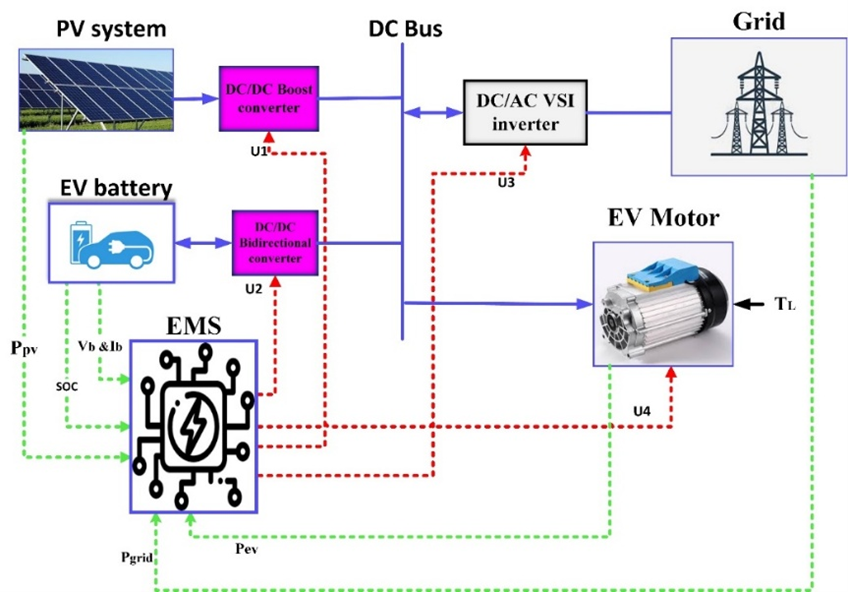
Figure 1 illustrates the architecture of the studied microgrid, comprising a PV array, BESS, EV load, and utility grid under a centralized LF-PSO EMS approach. The DC bus serves as the common energy coupling point, enabling bidirectional power exchange among the generation units, storage system, and load. The EMS generates the control signals (U1-U4) to coordinate the operation of the power converters and grid-side inverter, ensuring instantaneous power balance, stable DC-link voltage regulation, and efficient energy management under varying operating conditions.
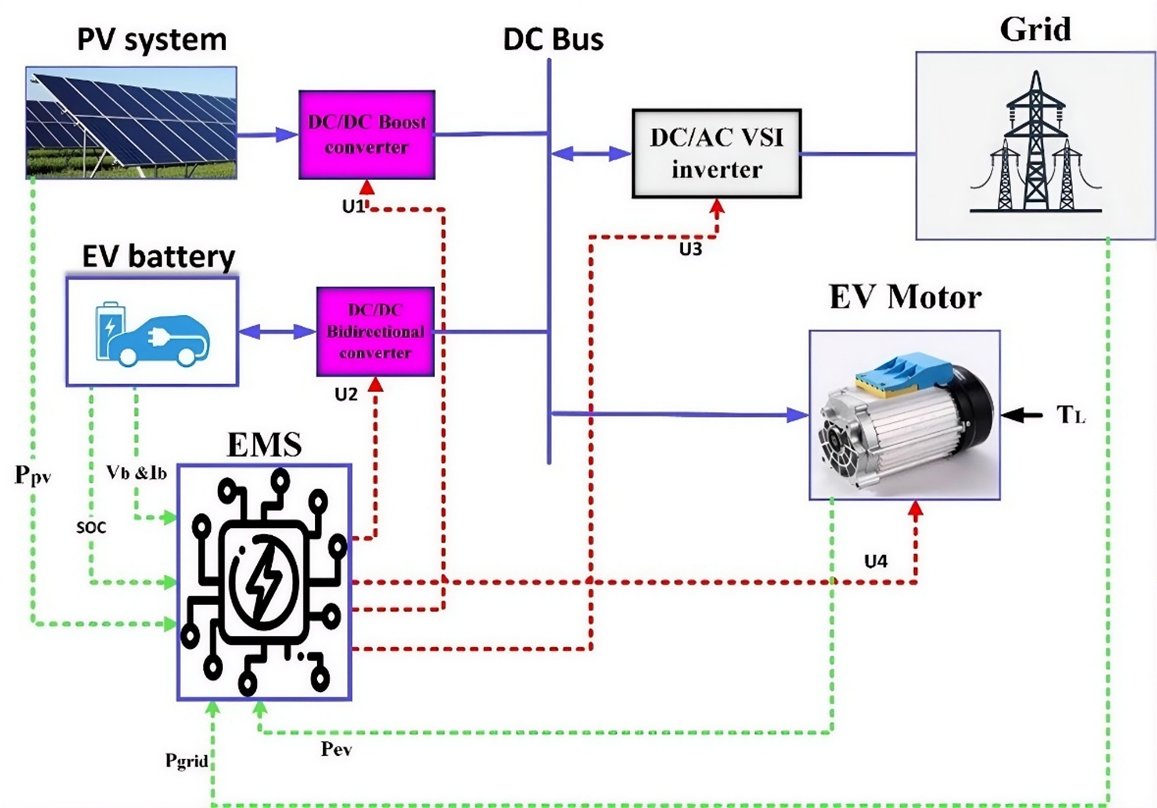
Figure 1. The proposed system diagram
Under normal operation conditions, the EMS supplies the PV power to the EV motor load via the DC bus, achieving the best utilization of renewable energy. The microgrid is connected to the grid by a DC/AC voltage source inverter, which allows the power flow in both directions, i.e., it enables the grid-import and grid-export modes. The proposed EMS guarantees smooth power transitions, stable DC bus voltage, and reduced dependence on forecasts and complex optimization processes.
Solar PV Modeling
The mathematical analysis of solar cells is shown using the single diode model. This model is used to study the characteristics of PV cells or modules due to its simplicity [41]-[44]. Figure 2 illustrates the electrical circuit of the PV model. The total current of the PV module or cell is given by Eq. (1).
| 
| (1) |
where  the light current,
  is the PV current,
 represents the diode current, and
  represents the parallel resistor current. The above equation can be written in Eq. (2) by adding the shunt and series resistances as follows:
| 
| (2) |
where,  represents PV voltage,
  denote the diode saturation current, is the photo-current,
  denote the thermal voltage,
  denote the series resistance,
  denote the parallel resistance and
  denote the coefficient of the semiconductor.
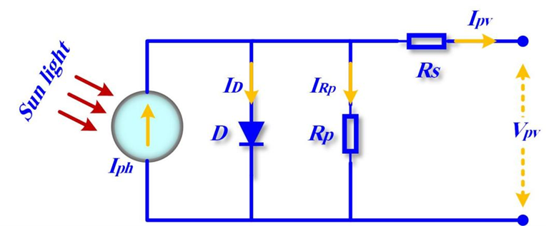
Figure 2. Typical solar PV model
Boost Converter Modeling
In the PV applications, the DC/DC converter is used to connect the PV array with the DC bus and implement the MPPT controller circuit. The main advantages of the boost converter are simplicity and high operational efficiency. The electrical scheme of the used boost converter is shown in Figure 3, and this converter can be analyzed by using Eq. (3) to Eq. (5) using continuous conduction mode [44].
where  ,
,  and
and  denote the inductance, input capacitance, and output capacitance, respectively. The input current is denoted by
  , while the output current is denoted by
  . The circuit's input and output voltages are denoted by
  and
and  , respectively. The converter's switching frequency is represented by
  , while the duty ratio is represented by
  Also, the ripple coefficients of the output voltage and the input current are denoted by
  and
and  , respectively. Also, the
  and
and  [26]. The values of the boost converter are
  and
and 
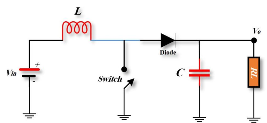
Figure 3. Boost converter circuit
Variable Step-Size MPPT Method
MPPT technology is important to the maximum efficiency of PV systems. The PV system extracts the maximum energy from the PV panels by using the MPPT technique. This improves the performance and efficiency of the PV system. Thus, the MPPT tracker optimizes the harvested PV energy and increases the conversion efficiency under normal or partial shading conditions [45][46]. In this paper, an improved Variable Step Size Incremental Conductance (VSS-INC) method is proposed to overcome the drawbacks of the conventional Incremental Conductance (INC) algorithm, particularly the trade-off between the tracking speed and the steady-state oscillations. The adaptive step-size mechanism provides fast convergence towards the maximum power point with oscillation suppression around the optimal operating point, which enhances the overall energy extraction efficiency of the PV array. Figure 4 shows the flowchart of the proposed INC method. The VSS-INC method is analyzed based on the formula (6) [45]. In addition, the variable step size of the duty ratio was considered as shown in Eq. (7).
| 
| (6) |
| 
| (7) |
where is the variation in PV output power,
  is the variation in PV voltage,
  is the variation in PV current (A),
  represents the change in the duty ratio, and
  denote the step size which taken
  .
.
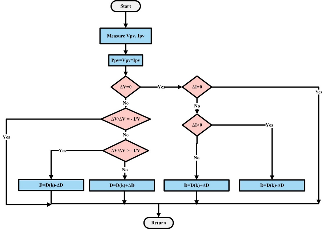
Figure 4. Flowchart of the VSS-INC method
EV Battery Modeling
A bidirectional converter is a main part in the DC and AC microgrids due to sharing the power between the vehicles, the power grid, and a DC bus system. This converter offers adaptability for battery within microgrid configurations. Bidirectional converters facilitate energy transfer in both directions, allowing battery to store energy from the grid or supply the local load [46][47]. The schematic representation of this converter is illustrated in Figure 5.
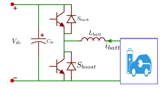
Figure 5. Battery storage DC/DC converter
The operation mode of the converter can be analyzed as follows:
Buck mode and charging operation: In charging operation, the bidirectional DC-DC converter operates in buck mode by turning on the upper switch (S buck). This switching action establishes the current conduction path through the power switch, the filter inductor, and the EV battery, thus reducing the DC-link voltage to the desired charging level. In this way, the electrical power is delivered from the utility grid to the battery, which is called G2V operating mode. In this case the terminal voltage of the battery is calculated by the following expression [48]:
| 
| (8) |
where  is the DC bus voltage,
  is the battery voltage,
  denote the duty for the buck switch.
Boost mode and discharging operation: In this configuration, the converter functions in boost mode when the lower switch ( ) is activated, transforming the battery voltage into the DC bus voltage. Consequently, current traverses the inductor and subsequently passes through the anti-parallel diode of the upper switch, thereby charging the capacitor. In this scenario, the energy transfer is inverted from the automobile to the grid, referred to as V2G, with the battery operating in discharge mode. As result, the bus output voltage is defined in Eq. (9) [47][48]:
| 
| (9) |
As shown in above equation, the DC voltage is controlled via  which is the duty cycle of the second switch.
DC/AC Motor Traction Modeling
The traction system of an EV is usually modeled with a Brushless DC (BLDC) motor because of its efficient operation, fast dynamic response, and low maintenance requirement. BLDC machines use electronic switching for commutation, instead of the mechanical switching found in conventional brushed DC motors. This leads to higher reliability, lower losses, and better performance. In addition, the BLDC motors have fast torque control, making them very suitable for accurately imitating the dynamic driving features and varying load conditions of the dynamic driving features and the varying load conditions of the EV applications. Figure 6 represents the control unit of a BLDC motor using a three-phase inverter, Hall-effect sensor and closed-loop control. The 3-phase inverter comprises six switches (S1–S6) for converting the DC input into 3-phase AC voltages supplied to the BLDC motor. The motor shaft position is detected using three Hall sensors ( ,
,  and
and  ) [49][50]. This unit generates the correct return electromotive force (EMF) signals and thus by determining the correct switching pattern for the inverter via the gate driver, the motor phases are commutated correctly. As observed, the PI controller also adjusts the inverter control to stabilize the motor's speed under load variations. The equations of the BLDC motor are given in Eq. (10) to Eq. (13).
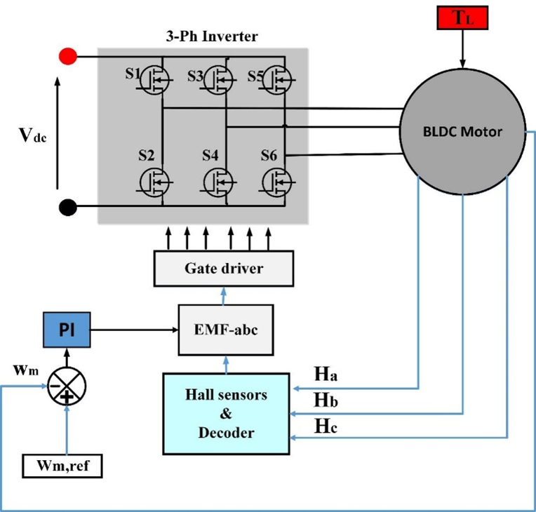
Figure 6. BLDC control drive
The above equations are expressed in term of matrix as follows:
| 
| (13) |
where  are the back electromotive forces,
  are the stator phase voltages,
  represents the phase resistance, the stator current of the motor are denoted by
  ,
,  , and
, and  .
.  ,
,  , and
, and  represents the self-inductances of the phases, and the mutual inductance of the motor are denoted by
  .
.
However, the traction mode of the EV motor load can be represented by the tractive force in Eq. (14).
| 
| (14) |
where  is the total tractive force in N,
  denote mass of the vehicle,
  is the air density kg/m3,
  is the area of the vehicle frontal in m²,
  represents the aerodynamic drag coefficient,
  is the speed in m/s, and
  is the road slop angle. In above equation also,
  denote the acceleration in m/s²,
  denote the gravitational acceleration 9.81 m/s²,
 represent the coefficient of the rolling resistance.
However, based on this analysis, the produced power is represented by Eq. (15).
| 
| (15) |
The electrical power taken by the BLDC motor from the DC bus can be derived from the following formula:
| 
| (16) |
where  is the drivetrain efficieny of the vehicel, and
  is the regenerative braking efficiency. At the regenerative braking mode, the mechanical power is
  . Therefore, the EV load power becomes negative and the power will return to the DC bus.
DC/AC Grid-Tied Inverter Modeling
The proposed system was linked with the DC bus and the utility grid via a DC/AC inverter. Figure 7 illustrates the DC/AC model control of this converter. The smart inverter integrated with the grid must actively synchronize to inject active power into the grid with a unity power factor [50][51]. The modeling of the inverter's control can be done based on Eq. (17) to Eq. (20).
| 
| (17) |
| 
| (18) |
where and
and  are the inverter output voltages in the synchronous dq-reference frame,
  and
and  are the inverter output currents in the dq-reference frame,
  and
and  are the reference values of the grid voltages. Also,
  represents the grid frequency, denotes the utility’s grid inductance,
  and
and  represents output signals of the controller. From Eq. (17) and Eq. (18), the required voltages under the dq-axis are determined as follows:
| 
| (19) |
| 
| (20) |
where  is the proportional gain and
  ,
,  and
and  represent the reference values of the grid currents.
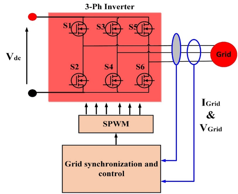
Figure 7. DC/AC Grid tied inverter control
PROPOSED EMS STRATEGY
PSO algorithm
PSO is a population-based metaheuristic optimization algorithm, initially introduced by James Kennedy and Russell Eberhart [35]. It is based on the social behavior of bird flocks and fish schools. In PSO, particles work together to identify the best solution. Each particle symbolizes a possible solution to the problem of optimization. The guidance comes from  , which is the best experience of the particle up to now, and also from
  , which is the best solution obtained so far by the whole swarm (i.e., the particle swarm optimization). The convergence to high-quality optimal solutions of PSO is achieved mainly through the regular update of particle positions and velocities. This is one of the reasons why particle swarm optimization is being used very successfully in a great variety of optimization problems in power and other systems. The reason for that is simple implementation, a very limited number of parameters, strong optimization power, and flexibility. The applications have been power system optimization, renewable energy applications, parameter identification, and controller tuning.
| 
| (21) |
| 
| (22) |
where,  denotes the particle velocity,
  is the particle position ,
  is the current iteration, is the inertia weight,
  and
and  are the cognitive and social learning coefficients, respectively, and
 and
and  are uniformly distributed random numbers within the interval (0, 1), while
  and
and  denote the personal best and global best positions.
In this work, PSO is used to optimize the parameters of the PI controller. Each particle denotes a candidate set of PI gains, and its fitness is evaluated based on the control performance of the microgrid. The particle positions are updated iteratively in the optimization process, and the optimal controller gains are obtained.
Furthermore, the optimization seeks to decrease the tracking error ( ) and enhance the transient response of the DC link voltage while ensuring stable power sharing of the studied MG. The objective function of the proposed EMS is given as follows:
| 
| (23) |
where  is the total time period of the simulation.
The Pseudocode of the PSO algorithm is illustrated in Algorithm 1. Also, the corresponding PSO hyperparameters have been explicitly presented in Table 1.
Algorithm 1. Pseudocode of the PSO algorithm |
1: Randomly initialize the position  and velocity and velocity  of all particles. of all particles. 2: determine the objective value of each particle. 3: Set  . . 4: Select the best particle as the global best (). 5: Set iteration counter  . . 6: while ( ) do ) do 8: Update the particle velocity Eq. (21) and Update the particle position Eq. (22) 7: Apply boundary constraints to . 8: Evaluate the new fitness value. 9: if Fitness () < Fitness ( ) then Update . ) then Update . 10: end if 11: if Fitness () < Fitness () then Update . 12: end if 13:  14: end while 15: Find as the optimal solution and return. |
Table 1. PSO algorithm parameters
Parameter | Symbol | Value |
Population size |
| 
|
Maximum iterations | 
| 
|
Inertia weight |
| 
|
Algorithm coefficients | 
| 
|
Number of runs | 
| 
|
LF-PSO based EMS strategy
The proposed LF-PSO strategy optimizes the proportional–integral controller gains instead of the conventional load-following approach with fixed controller parameters. Thus, the proposed method enhances the stability of the system and simultaneously efficiently utilizes the PV energy resource under abnormal and realistic weather conditions. The proposed EMS is based on a hierarchical control architecture with two coordinated control levels. The upper-level controller executes the supervisory energy management function by continuously checking the available PV generation, EV load demand, battery  , and grid operating conditions to compute the optimal reference battery power. Moreover, the controller coordinates the grid power import/export to keep the instantaneous power balance of the microgrid. The lower-level controller executes the reference commands generated by the supervisory controller in real-time. It controls the battery current by via adjusting the power bidirectional converter. The PSO-optimized the gains of the PI controller in order to maintain the DC-link voltage at its reference value. The optimized controller parameters significantly enhance the transient performance by reducing the voltage overshoot, accelerating the dynamic response and ensuring smooth transitions between G2V and V2G operation modes without affecting the system stability.
Differently from conventional EMS approaches, which rely on fixed controller tuning, the proposed LF-PSO framework provides robust energy coordination in fast-varying operating conditions in a continuous manner and respects the operational limits of the battery and power converters. This coordinated control strategy provides reliable operation of the integrated PV–EV microgrid with effective utilization of renewable energy, minimized unnecessary grid dependency, and improved battery power management. The schematic diagram of the implemented EMS is shown in Figure 8.
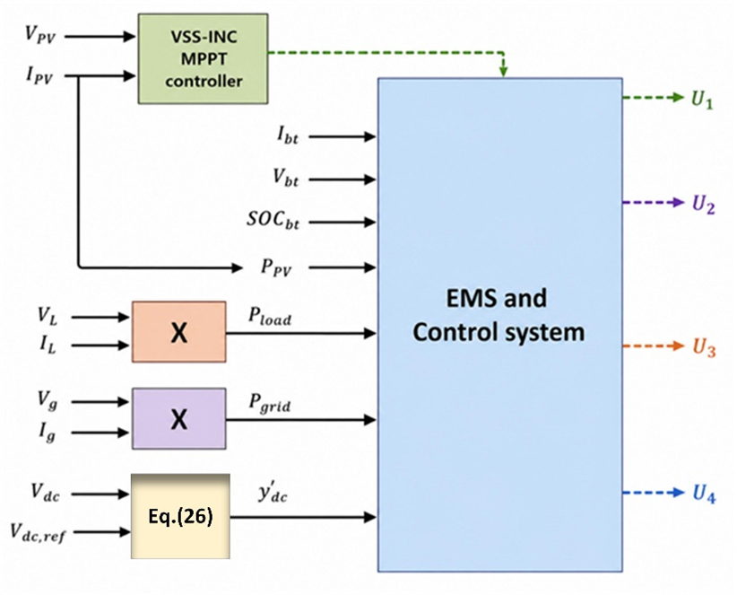
Figure 8. Proposed EMS diagram
The main energy balance in the DC bus can be written as follows:
| 
| (24) |
where  is the energy of the DC bus,
  is grid power,
  denote the output power of the solar array,
  represents the battery power, and
  is the total EV load.
From above equation, the power reference is defined by Eq. (25).
| 
| (25) |
The power signs are defined as follows,  : Battery discharging to DC bus,
  : battery at charging mode.
  : Import power from grid,
  : export power to system.
  : EV motor demand (load).
However, the PI controller is employed to regulate the DC bus voltage and produces the optimal reference power as given in Eq. (26). The battery delivers the necessary energy to the load during periods of low irradiance and facilitates V2G when the SOC is elevated. In this scenario, the bus voltage can be regulated according to the subsequent equation [30][31]:
| 
| (26) |
where  . As mentioned in above equation, the reference voltage is denoted by
  which equals
  , the tuned PI gains are represented by
  and
and  . The generated PV power is controlled via the VSS-INC MPPT controller and fed to the LF scheme. The grid power, PV power, and load power are calculated to generate the reference power of the EV battery in the higher level of the control. In addition, the low level of the control generates the PWM of the DC-DC bidirectional converter of the battery via a PI current controller. It can be inferred that the particular model incorporates a separated multi-loop system, which enables control over the inner loop, where the loop works towards regulating the amount of battery discharge and charge current, and then moves to the outer loop, which works towards controlling the amount of battery power. The loop that regulates the amount of charge seeks out the battery’s specified nominal power, which ends up producing a charging current that is referenced to the battery.
The output of the EMS is the duty cycle that controlled the buck-boost converter  as follows:
| 
| (27) |
where  is the battery reference generated from the EMS strategy,
  is the current of the EV battery. The gains of the battery controller are optimized to achieve the best duty ratio using the
  and
and  . However, the SOC of the battery at time (t) can be estimated based on the following equation [25],[32]:
| 
| (28) |
where  is the battery capacity and
 is the initial SOC value. Also, the limits of the PI gains are given in Eq. (29).
| 
| (29) |
where  and the maximum limits are
  .
.
Figure 9 reports the methodology framework of the LF-PSO approach. The EMS (Figure 10) method identifies the power generated by the PV system, the power consumed by the EV motor (), the battery SOC, and the availability of the power grid. As presented in Eq. (25), the net power required is calculated to check if the PV power sufficiently meets the EV load. The EMS optimally manages power flow based on PV generation, EV demand, and battery SOC. Excess PV power is prioritized for EV supply, battery charging within SOC limits, and grid export. Simultaneously, the EMS maintains the DC-link voltage at its reference value at , ensuring stable system operation, reliable power exchange, and high-power quality.
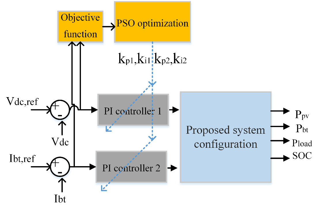
Figure 9. Proposed framework of the LF-PSO optimization method
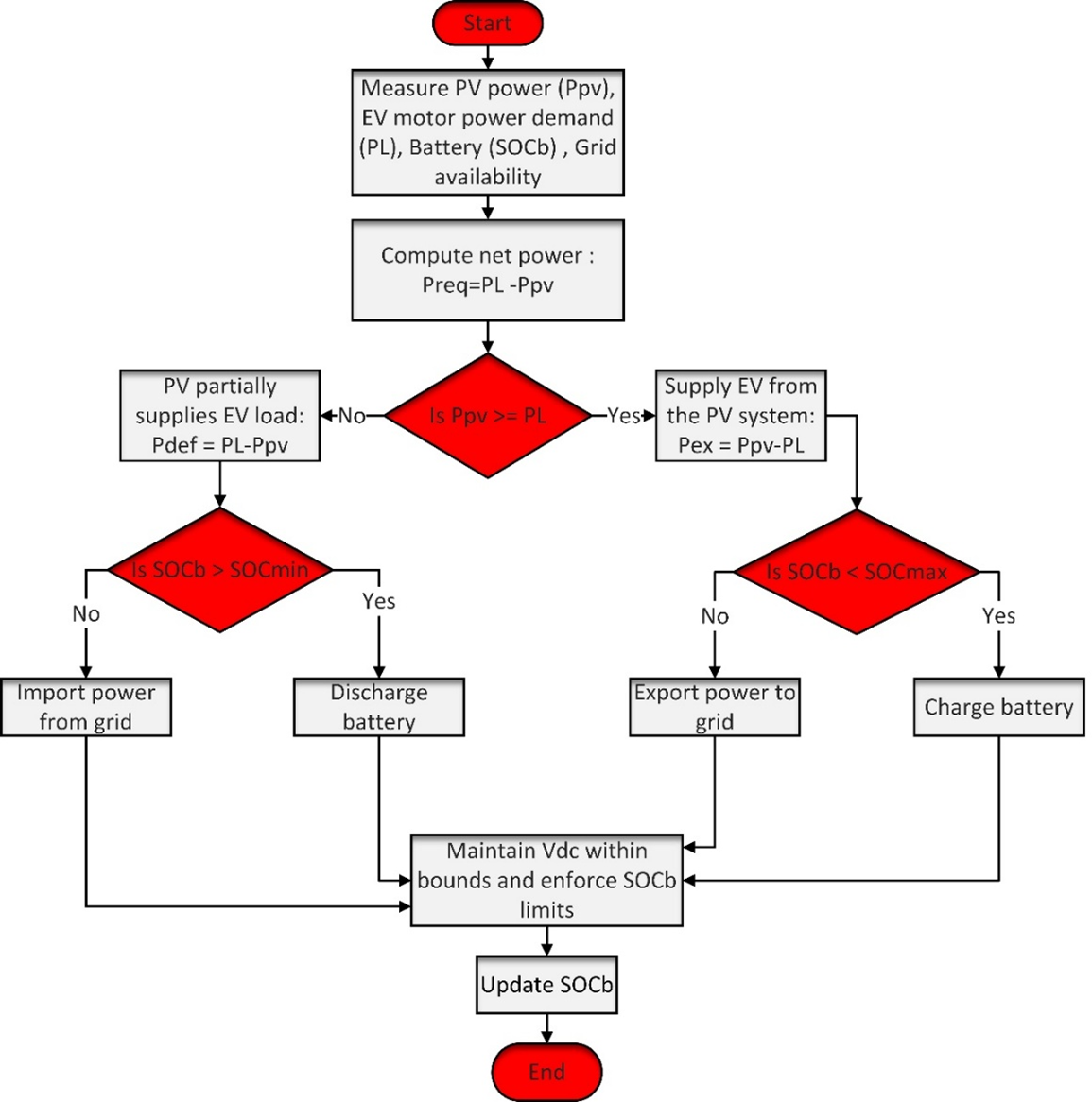
Figure 10. Flowchart of the proposed EMS strategy
RESULTS AND DISCUSSION
In this section, the capability of the designed LF-PSO based EMS is evaluated in extensive simulation studies in MATLAB/Simulink software. Moreover, the proposed strategy is verified for both islanded and grid-connected operation modes, considering different operation scenarios such as V2G and G2V operation, variable and real solar irradiance profiles, and dynamic EV loading conditions. These case studies are to show the ability of the proposed controller to realize stable power management, efficient energy sharing, and reliable system operation in the presence of changing environmental and loading conditions. The main simulation parameters of the analyzed microgrid are presented in Table 2.
Table 2. Main parameters of the simulated study
Parameter | Value |
PV module type | Kyocera Solar KC200GT |
Number of parallel strings | 
|
Series-connected modules per string | 
|
Total number of PV modules | 
|
Rated power per PV module | 
|
Maximum PV array power | 
|
PV voltage at maximum power point | 
|
PV open-circuit voltage | 
|
DC bus reference voltage |
|
Battery type | Lithium-ion |
Battery nominal voltage |
|
Battery rated capacity |
|
Battery nominal energy capacity | 
|
Initial battery SOC | 
|
Battery response time | 
|
Grid voltage | 400 V, line-to-line RMS |
Fundamental frequency | 
|
Converter switching frequency | 
|
EV motor rated power | 
|
| 
|
| 
|
| 
|

| 
|
Motor type | BLDC |
Stator phase resistance | 
|
Stator phase inductance | 
|
Permanent magnet flux linkage | 
|
Back-EMF flat area | 
|
Rotor inertia |  
|
Viscous damping coefficient |  10^(-5) 10^(-5) 
|
Number of pole pairs | 
|
Static friction torque | 
|
Case I: Evaluation Under Variable Solar Irradiation
In this case, the performance of the proposed LF-PSO-based energy management system is studied under variable solar irradiance conditions to study its capability in maintaining stable PV operation and effective MPPT. The solar irradiance is 0 W/m² at first, as shown in Figure 11, then increases to 800 W/m² between 0.8 s and 1.5 s, and then goes back down to 200 W/m². In this simulation, the cell temperature is kept constant at 25°C. Figure 12 shows the corresponding PV electrical characteristics. It can be seen that the PV voltage, current and output power closely follow the variations of the irradiance with fast dynamic response and negligible oscillations, which shows the effectiveness of the implemented MPPT algorithm. The PV array is operating at an irradiance of 800 W/m² and is supplying about 17 kW, which is in line with the expected operating conditions. The good transient response demonstrates the ability of the proposed control strategy to correctly extract the available maximum power while keeping the system operation stable in the case of fast irradiance changes. Figure 13 displays the obtained results under Case I. During the first islanded phase ( ),
),  and the utility grid is disconnected. In this time interval, the load demand power is
  . The simulation begins with a short transient, but the battery power converges quickly to the load level required, confirming that the EMS can keep the load continuous without renewable generation and without grid support.
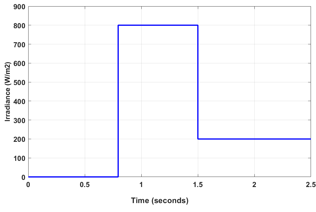
Figure 11. Profile of the solar irradiance under Case I
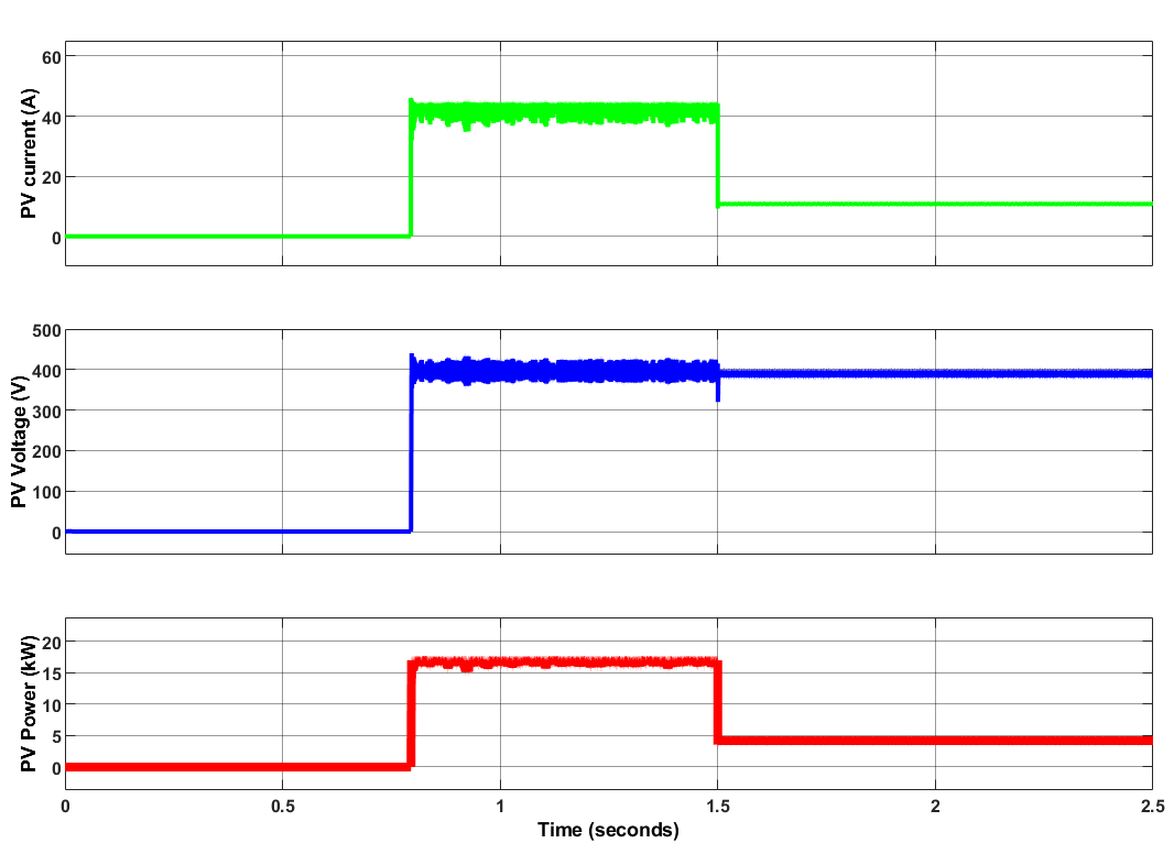
Figure 12. Obtained results of the PV system
At  , the PV power increases steeply to about
  . The load is almost constant. Therefore, the renewable power available is larger than the load demand, and the EMS rapidly dispatches the excess to the EV battery and the utility grid. The EV battery switches from charging to discharging, and the unwanted power is delivered to the utility grid. The transient peak in grid power is due to the sudden change in irradiance and the switch from islanded to grid-connected operation. At
  , as the irradiance decreases, the PV output reduces to around
  , which is less than the load demand. Therefore, the power flow direction is reversed, and the EV battery switches from charging to discharging to compensate for the renewable generation deficit. The rest of the power requirement is supplied by the utility grid, with the sign convention adopted. The battery and the grid respond in coordination, thus avoiding any load supply interruption and showing that the EMS is not dependent on a single source when the PV generation is not enough. The short time of transition and the steady power levels after that show good coordination between the PV array, EV battery, load, and grid. At
  , the load increases from about to nearly
  due to the applied motor-torque variation while the PV output is almost constant. As a result, there is a simultaneous increase in low PV generation and load demand while the system settles to a new steady operating point with no apparent sustained oscillations. This verifies the robustness of the LF-PSO strategy against the combined source and load disturbance.
Figure14 displays the bus voltage curves. As observed, the measured voltage is stabilized according to its reference value of with minimal overshoot value. During the switching events a small transient overshoot can be observed, especially at around  when the operating mode switches from islanded to grid-connected and the PV generation increases rapidly. This behavior shows the effectiveness of the optimized PI controller obtained using the PSO algorithm to provide reliable power sharing between the PV array, BESS, utility grid, and EV under highly dynamic operating conditions. Figure 15 presents the battery , battery current, and battery terminal voltage during the simulation. The small variations around the nominal value of of the SOC profile show that the proposed EMS can use the battery as a short-term energy buffer instead of excessive charging/discharging cycles. This controlled operation helps to extend the battery lifetime and improve the system performance. As observed, a current of
  is roughly equivalent to a battery discharge; on the other hand, the battery charges when the current is negative, i.e., during the interval
  . This shows that surplus PV energy is feeding into the battery. Besides that, battery cell voltage only varied a little. It stayed essentially unchanged at about
  and only experienced minor voltage changes during mode changes.
Figure 16 illustrates the waveforms of grid voltage and current for the case I scenario. It can be observed that the grid voltage is sinusoidal and stable during the whole simulation, but the grid current varies dynamically according to the required power exchange between the presented system and the utility network. The transient oscillations around and  are related to the sudden change of PV generation and the transition between charging and discharging operating modes. But these oscillations vanish quickly without creating long-term instability. The zoomed waveforms show that the grid voltage and current still have the high-quality sinusoidal characteristics after each transient period. The efficient operation of the controller is shown by the absence of significant waveform distortion, which is beneficial for maintaining good power quality in the grid-side inverter.
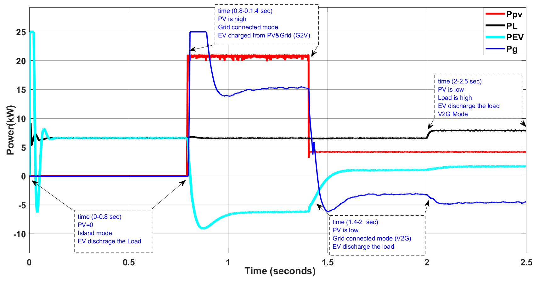
Figure 13. Obtained results under case I
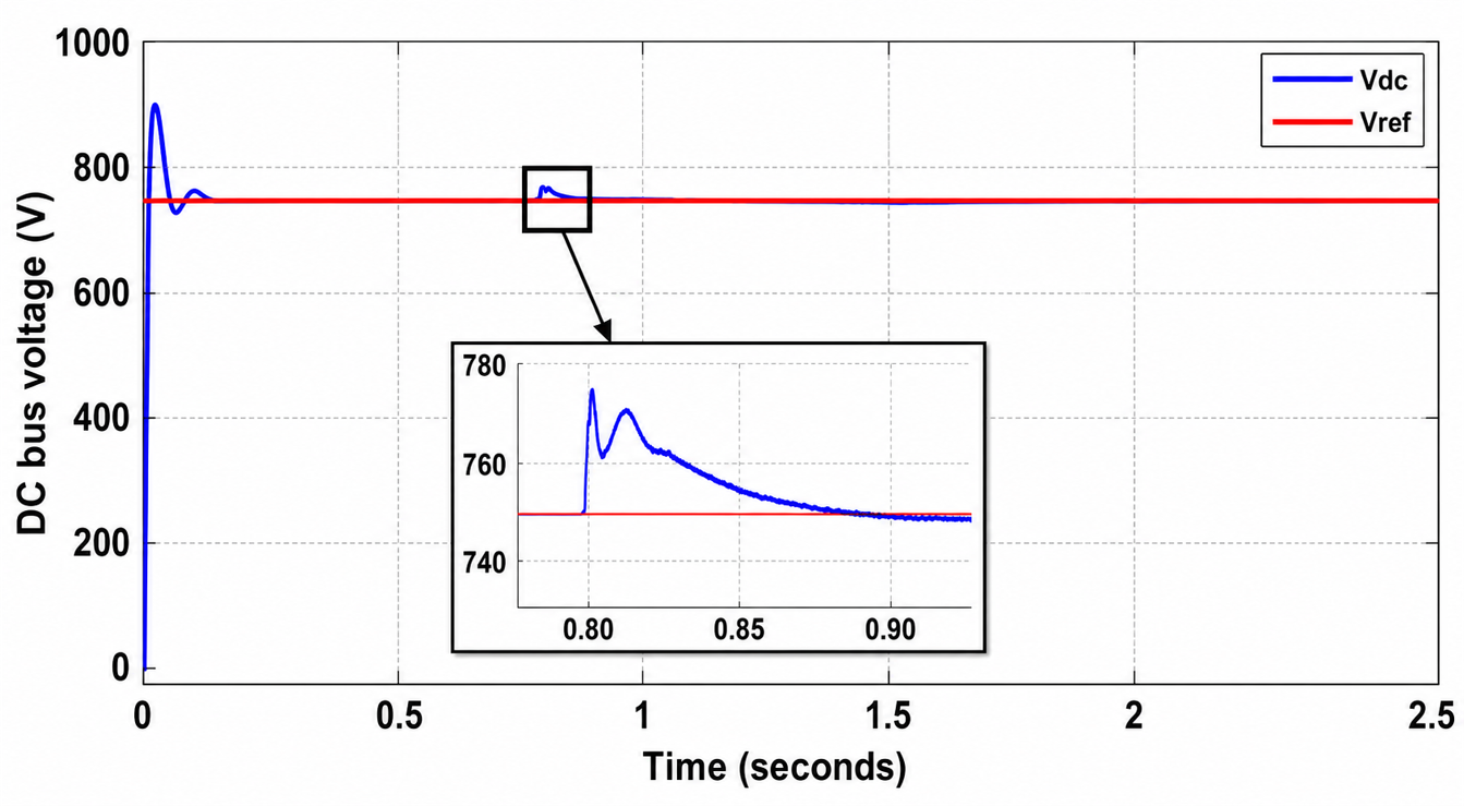
Figure 14. DC bus voltage result
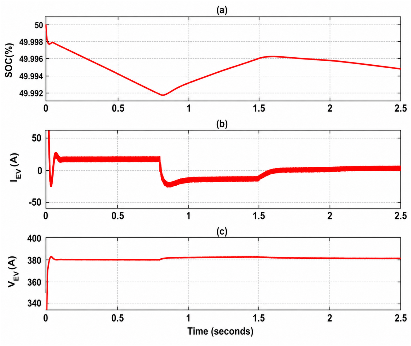
Figure 15. (a) SOC (b) output current of the battery (c) voltage of the battery
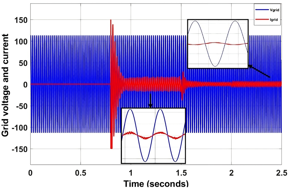
Figure 16. Grid voltage and current under Case I
Case II: Evaluation Under Real Irradiation Profile
This section examines the performance of the proposed LF-PSO-based EMS system under a realistic solar irradiance profile to assess its ability to handle continuous power fluctuations from renewable sources. In contrast, the previous case considers step changes in irradiance, while this case focuses on practical operations that continuously mimic changes in PV output due to variations in the sun's energy availability. Figure 17 reports the adopted irradiance profile during the whole simulation period. The fluctuating irradiance leads to corresponding power variations in the PV output.
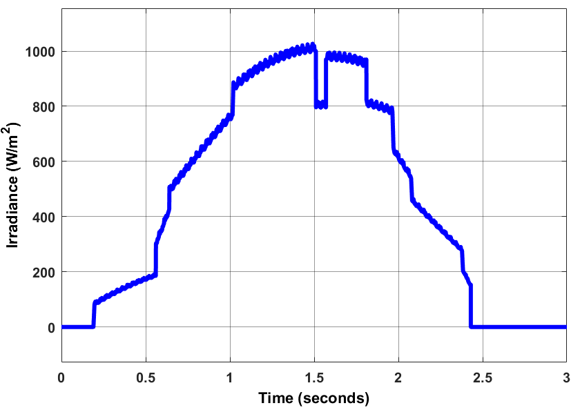
Figure 17. Realistic irradiance profile
The obtained PV voltage, current, and output power are given in Figure 18. As observed, the tracking of the maximum power point of the MPPT controller is achieved with continuous irradiance change. PV electrical variables present smooth dynamic responses with very little oscillation around the steady state. The power dispatch of the studied system is displayed in Figure 19. As noted in this figure, the generation of PV is at , which results in the availability of surplus clean energy. In the time interval from  , the suggested EMS is working in
  mode with supplying
  of the EV load. The proposed EMS continuously updates the power sharing strategy so as to keep the instantaneous power balance in the microgrid as the PV generation decreases. When PV and grid power are not sufficient to meet the load demand, the battery will automatically change to the discharge mode to support the DC bus, thus ensuring the uninterrupted power supply. The EMS initiates the
  operation at
  by discharging the battery and stabilize the bus voltage. The obtained findings demonstrate the effectiveness of the used LF-PSO strategy for coordinating multiple energy sources under realistic renewable energy conditions.
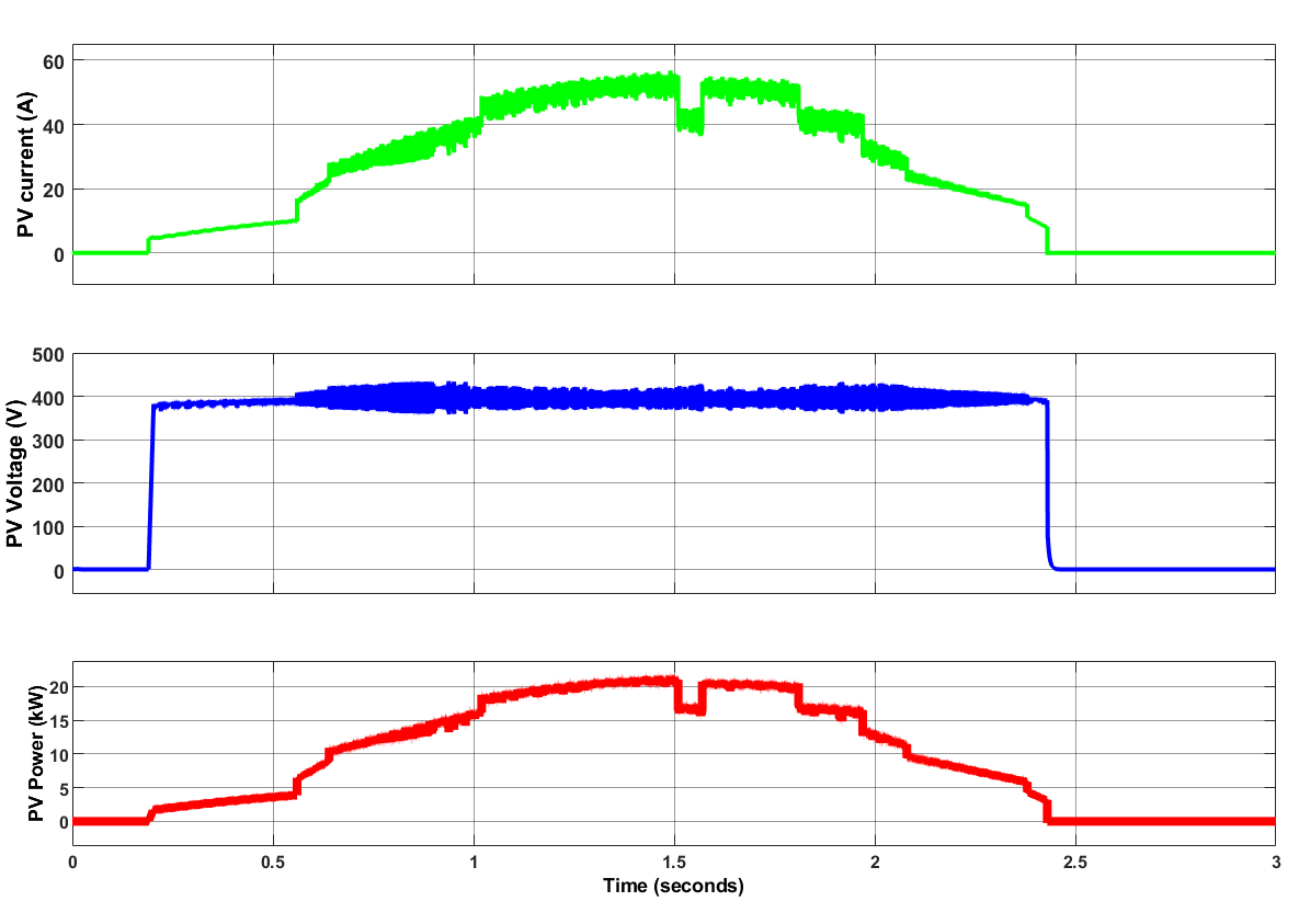
Figure 18. Obtained results of the PV system
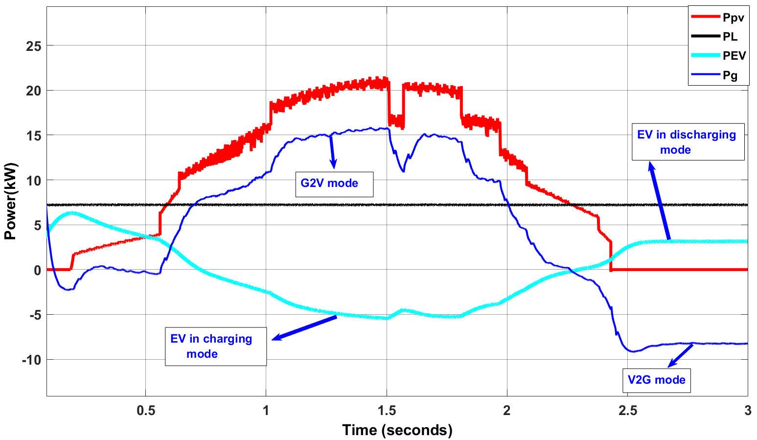
Figure 19. System power curves under real irradiance profile
Figure 20 presents the waveforms of the grid voltage and current under real irradiance. The grid voltage is kept in a constant sinusoidal form during the simulation time. The grid current is always with same phase of the utility grid (unity power factor). Figure 21 displays a battery dynamic behavior under a real irradiance profile. SOC is kept almost the same as its nominal level of  and the minor variances over the simulation can be attributed. Battery current reverses direction according to the available PV power, indicating that charge-discharge modes change without abrupt oscillations.
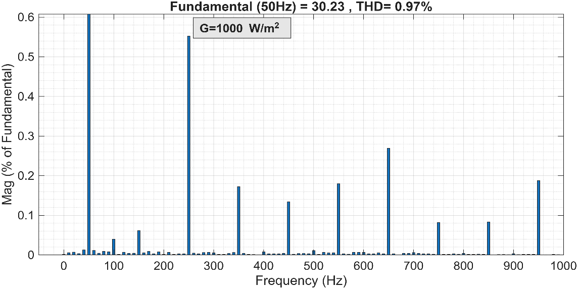
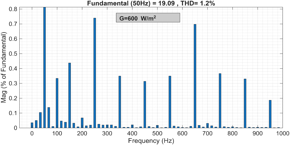
The steady-state grid voltage and current waveforms are shown in Figure 22, which reveals that the injected grid current is almost in phase with the utility-grid voltage, which confirms the high-power factor achieved by the proposed LF-PSO strategy. Also, FFT-based harmonic spectrum analyses are performed under different irradiance conditions (1000 W/m² and 600 W/m²) to quantify the current harmonic distortion (see Figure 23). The obtained results show a current THD of 0.97% at 1000 W/m² and 1.20% at 600 W/m², confirming that the proposed EMS maintains an excellent power quality under different operating conditions. However, it is found that the injected grid current is nearly in phase with the grid voltage, having a power factor near to unity. Also, the FFT analysis of the injected grid current at different irradiance levels shows that the proposed controller effectively mitigates the harmonic components. These results verify that the proposed LF-PSO strategy achieves excellent power quality while maintaining stable operation under varying renewable generation conditions.
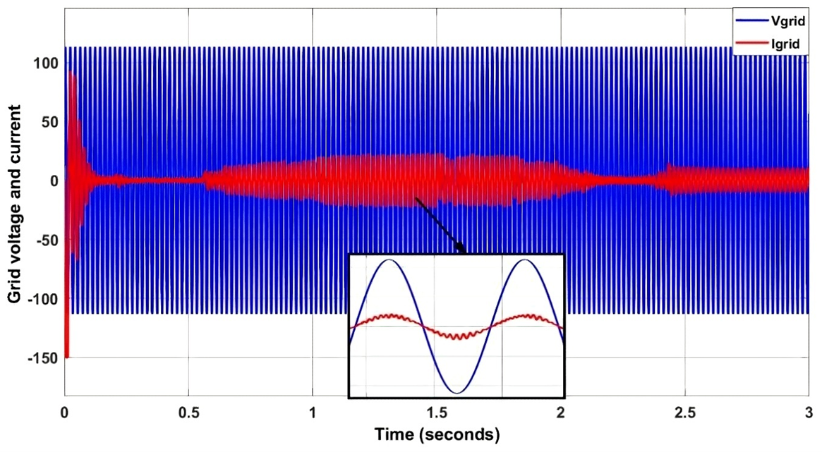
Figure 20. Waveforms of the grid voltage and current under real irradiance
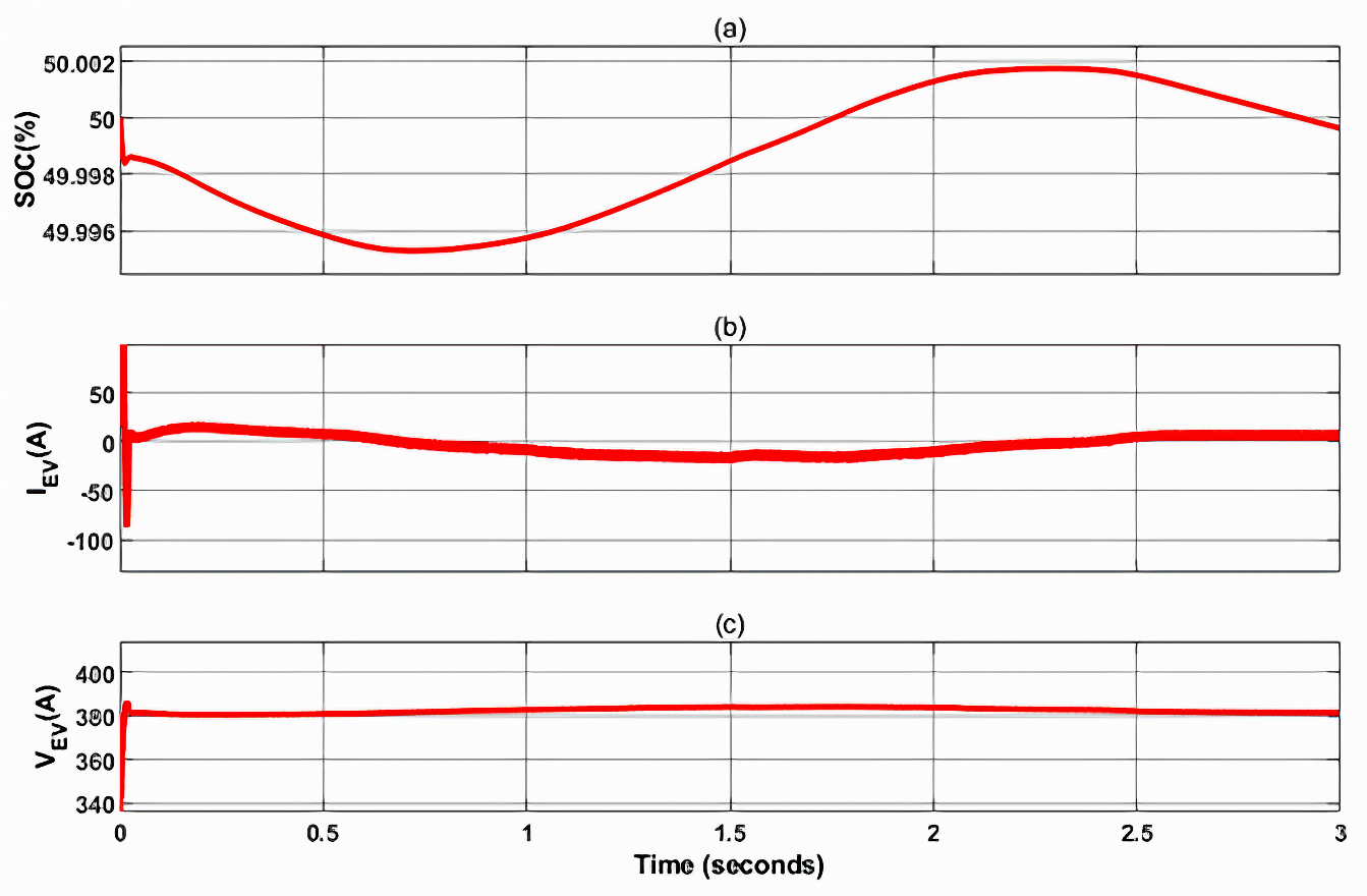
Figure 21. Battery response parameters under Case II
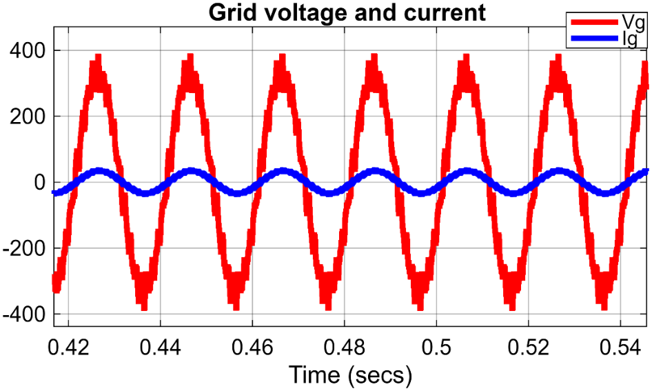
Figure 22. Grid voltage and current waveforms
|
(a) |
|
(b) |
Figure 23. FFT analysis of the injected grid current (a) FFT at 1000W/m2 and (b) FFT at 600 W/m2
In summary, the achieved findings indicate that the recommended LF-PSO-based EMS proficiently manages the power distribution among the PV-EV system across various operational scenarios. The suggested controller ensures a consistent DC-link voltage, mitigates fluctuations in PV power, attains a grid-current THD of 0.95%, and sustains a near-unity power factor while facilitating dependable bidirectional power transfer during G2V and V2G operations. From an engineering perspective, these findings indicate that the proposed LF-PSO-based EMS can improve the operational reliability and power quality of renewable microgrids by providing smooth energy coordination, reducing transient oscillations, and maintaining stable system operation. Furthermore, the low implementation complexity makes the proposed strategy suitable for practical grid-connected PV-EV applications.
Finaly, the principal advantages of the proposed approach are simple implementation, effective power-sharing capability, low harmonic distortion, and high power factor at different operating conditions. The present study is limited to validation based on MATLAB/Simulink. Thus, future work will focus on experimental validation using hardware-in-the-loop (HIL) and laboratory-scale implementation to further validate the presented energy management strategy under real operating conditions.
Comparison and Assessment
To verify the effectiveness of the proposed LF-PSO EMS, a comparative analysis with many other EMS techniques from the literature was carried out. It mainly included the conventional PI control, fuzzy logic control, ANN, and flatness-based EMS. The findings obtained from this comparative exercise are presented in Table 3 and reveal a wide range of performance indicators, including PV power stability, DC-link voltage regulation, total harmonic distortion (THD), grid power factor, dynamic response, and implementation complexity. In addition, values of reported THD and power factor were validated through FFT analysis.
This analysis shows the superiority of the proposed LF-PSO-based EMS in terms of dynamic performance. It allows for a smooth and effective power coordination among the PV array, BESS, utility grid, and EV under various operational conditions. The optimized controller keeps the bidirectional power flow steady while greatly reducing changes in DC-link voltage and PV power. In particular, the DC-bus voltage overshoot is reduced to  compared with
  reported for the PI, fuzzy logic, ANN, and flatness-based methods, respectively. This improvement indicates a faster transient response and enhanced DC-link voltage stability. Moreover, the proposed controller achieves the lowest grid-current
  and the highest power factor
  ), confirming superior grid power quality. Although some existing methods exhibit acceptable MPPT performance, they generally involve higher implementation complexity or larger transient oscillations. Therefore, the proposed LF-PSO-based EMS provides an effective balance between dynamic performance, power quality, implementation simplicity, and practical applicability for renewable microgrids with electric vehicle integration.
Table 3. Comparison of the proposed EMS with the other EMS methods
Metric | Proposed EMS | PI [31] | Fuzzy logic [32] | ANN [21] | Flatness [49] |
DC Bus voltage overshoot (%) | 4.7 | 30 | 13 | 15 | 7 |
PV power fluctuations | Very low | High | low | low | low |
Current THD content | 0.95 | 3.5 | 1.4 | 2.2 | 10 |
Power factor | 0.999 | 0.967 | 0.998 | 0.985 | 0.995 |
Complexity | low | Very low | Moderate | High | Very high |
MPPT tracking efficiency | Very high | High | Very high | High | Very high |
CONCLUSION AND FUTURE WORK
This paper introduced an efficient energy management system for controlling the power sharing based on a solar PV array, battery energy storage system (BESS), electric vehicle (EV), and utility grid in a renewable-energy microgrid, using a load-following particle swarm optimization (LF-PSO) control technique. The new EMS scheme has been validated on the MATLAB/Simulink platform by simulating the microgrid operation under both a changing solar irradiance profile and a realistic irradiance profile. From the simulation results, it was evident that the proposed LF-PSO-based energy management strategy effectively regulates the instantaneous power without disrupting the system's stability. The suggested LF-PSO method maintains smooth transitions and efficient coordination in the case of power bidirectional exchanges between the EV and the utility grid, and the DC link voltage is kept stable with a minimum voltage drop during transitions and a very short voltage settling time. In terms of power system harmonics, the proposed EMS achieves a low total harmonic distortion (THD) of the grid current with  representing a significant
  reduction compared to the over
  THD typically produced by traditional PI controls. Furthermore, the method keeps a power factor higher than
  while minimizing the oscillation in PV's output and keeping the DC-link voltage regulation stable. The achieved results validate that the EMS strategy is a robust solution for PV-EV-integrated microgrids with efficient utilization of energy and high-power quality. However, the present work is limited to a MATLAB/Simulink-based validation. Future works will thus be focused on experimental validation in hardware-in-the-loop (HIL) and lab-scale implementations for a better assessment of the controller performance in real operating conditions. In addition, future work can be considered in this study as follows: (1) developing an optimized load-following EMS method for a hybrid microgrid system; (2) investigating the partial shading conditions on the PV system using a modern MPPT method; and (3) integrating different renewable energy sources such as wind energy to improve the system reliability and minimize the cost of operation.
REFERENCES
- S. J. Yaqoob, H. Arnoos, N. T. Alwan, M. Bajaj, I. M. Alwan, M. H. A. Aljanabi, B. A. Zneid, and M. S. Geremew, "Advanced maximum power point tracking in photovoltaic systems: A comprehensive review of classical, AI‐based, and metaheuristic optimization techniques," Eng. Rep., vol. 7, no. 9, p. e70404, 2025, https://doi.org/10.1002/eng2.70404.
- X. Sun, Z. Li, X. Wang, and C. Li, "Technology development of electric vehicles: A review," Energies, vol. 13, no. 1, p. 90, 2019, https://doi.org/10.3390/en13010090.
- K. Laadjal and A. J. M. Cardoso, "Estimation of lithium-ion batteries state-condition in electric vehicle applications: issues and state of the art," Electronics, vol. 10, no. 13, p. 1588, 2021, https://doi.org/10.3390/electronics10131588.
- W. Liu, T. Placke, and K. T. Chau, "Overview of batteries and battery management for electric vehicles," Energy Rep., vol. 8, pp. 4058–4084, 2022, https://doi.org/10.1016/j.egyr.2022.03.016.
- G. Sugumaran and N. A. Prabha, "A comprehensive review of various topologies and control techniques for DC‐DC converter‐based lithium‐ion battery charge equalization," Int. Trans. Electr. Energy Syst., vol. 2023, no. 1, p. 3648488, 2023, https://doi.org/10.1155/2023/3648488.
- A. Alkhalidi, M. K. Khawaja, and S. M. Ismail, "Solid-state batteries, their future in the energy storage and electric vehicles market," Sci. Talks, vol. 11, p. 100382, 2024, https://doi.org/10.1016/j.sctalk.2024.100382.
- R. Shah, V. Mittal, and A. M. Precilla, "Challenges and advancements in all-solid-state battery technology for electric vehicles," J, vol. 7, no. 3, pp. 204–217, 2024, https://doi.org/10.3390/j7030012.
- R. Manivannan, "Research on IoT-based hybrid electrical vehicles energy management systems using machine learning-based algorithm," Sustain. Comput.: Inform. Syst., vol. 41, p. 100943, 2024, https://doi.org/10.1016/j.suscom.2023.100943.
- P. Sivaraman and C. Sharmeela, "IoT‐based battery management system for hybrid electric vehicle," in Artificial Intelligent Techniques for Electric and Hybrid Electric Vehicles, pp. 1–16, 2020, https://doi.org/10.1002/9781119682035.ch1.
- M. Ghalkhani and S. Habibi, "Review of the Li-ion battery, thermal management, and AI-based battery management system for EV application," Energies, vol. 16, no. 1, p. 185, 2022, https://doi.org/10.3390/en16010185.
- N. M. Manousakis, P. S. Karagiannopoulos, G. J. Tsekouras, and F. D. Kanellos, "Integration of renewable energy and electric vehicles in power systems: a review," Processes, vol. 11, no. 5, p. 1544, 2023, https://doi.org/10.3390/pr11051544.
- K. Taghizad-Tavana, A. A. Alizadeh, M. Ghanbari-Ghalehjoughi, and S. Nojavan, "A comprehensive review of electric vehicles in energy systems: Integration with renewable energy sources, charging levels, different types, and standards," Energies, vol. 16, no. 2, p. 630, 2023, https://doi.org/10.3390/en16020630.
- N. Dharavat, N. K. Golla, S. K. Sudabattula, S. Velamuri, M. P. Kantipudi, H. Kotb, and K. M. AboRas, "Impact of plug-in electric vehicles on grid integration with distributed energy resources: A review," Front. Energy Res., vol. 10, p. 1099890, 2023, https://doi.org/10.3389/fenrg.2022.1099890.
- D. Gogoi, A. Bharatee, and P. K. Ray, "Implementation of battery storage system in a solar PV-based EV charging station," Electr. Power Syst. Res., vol. 229, p. 110113, 2024, https://doi.org/10.1016/j.epsr.2024.110113.
- Mohini, K. Chauhan, and R. K. Chauhan, "Solar and on-grid based electric vehicle charging station," in Electric Vehicle Charging Infrastructures and its Challenges, pp. 215–243, 2025, https://doi.org/10.1007/978-981-96-0361-9_10.
- G. A. Salvatti, E. G. Carati, R. Cardoso, J. P. da Costa, and C. M. de Oliveira Stein, "Electric vehicles energy management with V2G/G2V multifactor optimization of smart grids," Energies, vol. 13, no. 5, p. 1191, 2020, https://doi.org/10.3390/en13051191.
- S. Rafique, M. J. Hossain, M. S. Nizami, U. B. Irshad, and S. C. Mukhopadhyay, "Energy management systems for residential buildings with electric vehicles and distributed energy resources," IEEE Access, vol. 9, pp. 46997–47007, 2021, https://doi.org/10.1109/ACCESS.2021.3067950.
- M. U. Safder, M. A. Hossain, M. J. Sanjari, and J. Lu, "Rule‐based energy management system for autonomous voltage stabilization in standalone DC microgrid," Energy Sci. Eng., vol. 12, no. 10, pp. 4278–4296, 2024, https://doi.org/10.1002/ese3.1873.
- O. Ibrahim, M. S. Bakare, T. I. Amosa, A. O. Otuoze, W. O. Owonikoko, E. M. Ali, L. M. Adesina, and O. Ogunbiyi, "Development of fuzzy logic-based demand-side energy management system for hybrid energy sources," Energy Convers. Manage.: X, vol. 18, p. 100354, 2023, https://doi.org/10.1016/j.ecmx.2023.100354.
- E. González-Rivera, P. García-Triviño, R. Sarrias-Mena, J. P. Torreglosa, F. Jurado, and L. M. Fernández-Ramírez, "Model predictive control-based optimized operation of a hybrid charging station for electric vehicles," IEEE Access, vol. 9, pp. 115766–115776, 2021, https://doi.org/10.1109/ACCESS.2021.3106145.
- H. Bourenane, A. Berkani, K. Negadi, F. Marignetti, and K. Hebri, "Artificial neural networks based power management for a battery/supercapacitor and integrated photovoltaic hybrid storage system for electric vehicles," J. Eur. Syst. Autom., vol. 56, no. 1, pp. 139–147, 2023, https://doi.org/10.18280/jesa.560118.
- H. E. Ghadbane, S. Barkat, A. Houari, A. Djerioui, H. Abdelhak, and T. Mesbahi, "A load following energy management strategy for a battery-supercapacitor hybrid power system implemented with a PIL co-simulation approach," Smart Grids Sustain. Energy, vol. 9, no. 2, p. 32, 2024, https://doi.org/10.1007/s40866-024-00214-4.
- M. Manikandan, R. Saravanan, G. Kannayeram, and M. Saravanan, "Integrating renewable resources and electric vehicles: An approach for effective energy management in DC microgrid," Sol. Energy, vol. 299, p. 113775, 2025, https://doi.org/10.1016/j.solener.2025.113775.
- B. Xiong, L. Zhang, Y. Hu, F. Fang, Q. Liu, and L. Cheng, "Deep reinforcement learning for optimal microgrid energy management with renewable energy and electric vehicle integration," Appl. Soft Comput., vol. 176, p. 113180, 2025, https://doi.org/10.1016/j.asoc.2025.113180.
- M. Al-Dhaifallah, Z. M. Ali, M. Alanazi, S. Dadfar, and M. H. Fazaeli, "An efficient short-term energy management system for a microgrid with renewable power generation and electric vehicles," Neural Comput. Appl., vol. 33, no. 23, pp. 16095–16111, 2021, https://doi.org/10.1007/s00521-021-06247-5.
- Y.-H. Lin and Y.-H. Hung, "Integrated thermal and energy management systems using particle swarm optimization for energy optimization in electric vehicles," Case Stud. Therm. Eng., vol. 71, p. 106136, 2025, https://doi.org/10.1016/j.csite.2025.106136.
- A. Fathy, "Bald eagle search optimizer-based energy management strategy for microgrid with renewable sources and electric vehicles," Appl. Energy, vol. 334, p. 120688, 2023, https://doi.org/10.1016/j.apenergy.2023.120688.
- P. A. Gbadega and A. K. Saha, "Predictive control of adaptive micro-grid energy management system considering electric vehicles integration," Int. J. Eng. Res. Afr., vol. 59, pp. 175–204, 2022, https://doi.org/10.4028/p-42m5ip.
- M. Li, M. Aksoy, and S. Samad, "Optimal energy management and scheduling of a microgrid with integrated electric vehicles and cost minimization," Soft Comput., vol. 28, no. 3, pp. 2015–2034, 2024, https://doi.org/10.1007/s00500-023-09168-8.
- T. Hai, N. S. S. Singh, and F. Jamal, "Energy management of a microgrid with integration of renewable energy sources considering energy storage systems with electricity price," J. Energy Storage, vol. 110, p. 115191, 2025, https://doi.org/10.1016/j.est.2024.115191.
- A. Saffar and A. Ghasemi, "Energy management of a renewable-based isolated micro-grid by optimal utilization of dump loads and plug-in electric vehicles," J. Energy Storage, vol. 39, p. 102643, 2021, https://doi.org/10.1016/j.est.2021.102643.
- A. Aldosary, M. Rawa, Z. M. Ali, M. Latifi, A. Razmjoo, and A. Rezvani, "Energy management strategy based on short-term resource scheduling of a renewable energy-based microgrid in the presence of electric vehicles using θ-modified krill herd algorithm," Neural Comput. Appl., vol. 33, no. 16, pp. 10005–10020, 2021, https://doi.org/10.1007/s00521-021-05768-3.
- V. Boglou, C.‐S. Karavas, A. Karlis, and K. Arvanitis, "An intelligent decentralized energy management strategy for the optimal electric vehicles' charging in low‐voltage islanded microgrids," Int. J. Energy Res., vol. 46, no. 3, pp. 2988–3016, 2022, https://doi.org/10.1002/er.7358.
- A. Abuelrub, F. Hamed, J. Hedel, and H. M. Al-Masri, "Feasibility study for electric vehicle usage in a microgrid integrated with renewable energy," IEEE Trans. Transp. Electrif., vol. 9, no. 3, pp. 4306–4315, 2023, https://doi.org/10.1109/TTE.2023.3243237.
- T. Hai, J. Zhou, A. Rezvani, B. N. Le, and H. Oikawa, "Optimal energy management strategy for a renewable based microgrid with electric vehicles and demand response program," Electr. Power Syst. Res., vol. 221, p. 109370, 2023, https://doi.org/10.1016/j.epsr.2023.109370.
- M. Manikandan, R. Saravanan, G. Kannayeram, and M. Saravanan, "Integrating renewable resources and electric vehicles: An approach for effective energy management in DC microgrid," Sol. Energy, vol. 299, p. 113775, 2025, https://doi.org/10.1016/j.solener.2025.113775.
- B. Xiong, L. Zhang, Y. Hu, F. Fang, Q. Liu, and L. Cheng, "Deep reinforcement learning for optimal microgrid energy management with renewable energy and electric vehicle integration," Appl. Soft Comput., vol. 176, p. 113180, 2025, https://doi.org/10.1016/j.asoc.2025.113180.
- A. Khatiri, S. Y. M. Mousavi, and S. Golestan, "Quantum neural networks for optimal energy management in renewable based microgrids with plug-in electric vehicles and battery energy storages," J. Energy Storage, vol. 129, p. 117304, 2025, https://doi.org/10.1016/j.est.2025.117304.
- G. Xiao, H. Liu, and J. Nabatalizadeh, "Optimal scheduling and energy management of a multi-energy microgrid with electric vehicles incorporating decision making approach and demand response," Sci. Rep., vol. 15, no. 1, p. 5075, 2025, https://doi.org/10.1038/s41598-025-88776-w.
- W. R. Resen, S. Sabeeh, and S. J. Yaqoob, "Energy management system using load following-terminal slide mode control strategy in DC microgrid with hybrid energy storage system," AIMS Electron. Electr. Eng., vol. 10, no. 1, pp. 150–179, 2026, https://doi.org/10.3934/electreng.2026007.
- S. J. Yaqoob, S. Kamel, F. Jurado, S. Motahhir, A. Chalh, and H. Arnoos, "Efficient and cost-effective maximum power point tracking technique for solar photovoltaic systems with Li-ion battery charging," Integration, vol. 100, p. 102298, 2025, https://doi.org/10.1016/j.vlsi.2024.102298.
- S. J. Yaqoob, A. L. Saleh, S. Motahhir, E. B. Agyekum, A. Nayyar, and B. Qureshi, "Comparative study with practical validation of photovoltaic monocrystalline module for single and double diode models," Sci. Rep., vol. 11, no. 1, p. 19153, 2021, https://doi.org/10.1038/s41598-021-98593-6.
- S. J. Yaqoob, S. Kamel, and F. Jurado, "A low-cost and efficient fuzzy logic MPPT technique based current sensor-less strategy for solar battery charging," in Proc. 2023 24th Int. Middle East Power Syst. Conf. (MEPCON), pp. 1–6, 2023, https://doi.org/10.1109/MEPCON58725.2023.10462389.
- F. A. Abbas, A. A. Obed, and S. J. Yaqoob, "A comparative study between the most used MPPT methods and particle swarm optimization method for a standalone PV system under fast change in irradiance level," in AIP Conference Proceedings, vol. 2804, no. 1, 2023, p. 050007, https://doi.org/10.1063/5.0154314.
- I. N. Syamsiana, R. N. A. Wijaya, A. D. W. Sumari, R. N. Amalia, and H. Sungkowo, "Maximization of battery charging efficiency in photovoltaic systems through PI controlled SEPIC converter with P&O MPPT," Results Eng., vol. 26, p. 105469, 2025, https://doi.org/10.1016/j.rineng.2025.105469.
- E. Rwamurangwa, J. D. Gonzalez, and A. Butare, "Integration of EV in the grid management: The grid behavior in case of simultaneous EV charging-discharging with the PV solar energy injection," Electricity, vol. 3, no. 4, pp. 563–585, 2022, https://doi.org/10.3390/electricity3040028.
- F. M. Shakeel and O. P. Malik, "Vehicle-to-grid technology in a micro-grid using DC fast charging architecture," in Proc. 2019 IEEE Can. Conf. Electr. Comput. Eng. (CCECE), pp. 1–4, 2019, https://doi.org/10.1109/CCECE.2019.8861592.
- S. J. Yaqoob, S. Ferahtia, A. A. Obed, H. Rezk, N. T. Alwan, H. M. Zawbaa, and S. Kamel, "Efficient flatness based energy management strategy for hybrid supercapacitor/lithium-ion battery power system," IEEE Access, vol. 10, pp. 132153–132163, 2022, https://doi.org/10.1109/ACCESS.2022.3230333.
- S. Poorani, P. Kathirvel, T. M. Murugan, and P. J. Shermila, "A novel differential flatness control approach of an electric vehicle using energy management methodology," Iran. J. Sci. Technol., Trans. Electr. Eng., vol. 49, no. 4, pp. 1977–1991, 2025, https://doi.org/10.1007/s40998-025-00819-0.
- J. C. Peña-Aguirre, A.-I. Barranco-Gutiérrez, J. A. Padilla-Medina, A. Espinosa-Calderon, and F. J. Pérez-Pinal, "Fuzzy logic power management strategy for a residential DC-microgrid," IEEE Access, vol. 8, pp. 116733–116743, 2020, https://doi.org/10.1109/ACCESS.2020.3004611.
- S. J. Yaqoob, H. Arnoos, M. A. Qasim, E. B. Agyekum, A. Alzahrani, and S. Kamel, "An optimal energy management strategy for a photovoltaic/li-ion battery power system for DC microgrid application," Front. Energy Res., vol. 10, p. 1066231, 2023, https://doi.org/10.3389/fenrg.2022.1066231.
Zaid KH. Sadane (A Load-following Particle Swarm Optimization-based Energy Management Technique for Integrating Electric Vehicles into a Renewable Microgrid System)