ISSN: 2685-9572 Buletin Ilmiah Sarjana Teknik Elektro
Vol. 8, No. 4, August 2026, pp. 996-1018
Cross-Configured Wideband Multiple-Input Multiple-Output Antenna with Defected Ground Structure and Parasitic Directors for 2.7–12 GHz Ultra-Wideband and Sub-6 GHz Wireless Applications
Ramy Abduimawjood Mohammed, Uttam Laxman Bombale
Department of Technology, Shivaji University, Kolhapur, India
ARTICLE INFORMATION |
| ABSTRACT |
Article History: Received 28 April 2026 Revised 02 July 2026 Accepted 27 July 2026 |
| 
Modern Ultra-Wideband (UWB) and sub-6 GHz systems require compact antennas with wide bandwidth, enhanced gain, low coupling, and reliable diversity. This study develops a simulation-based wideband MIMO antenna that addresses the bandwidth and isolation limitations of conventional planar microstrip antennas. The research contribution is a progressive antenna family based on a microstrip-fed planar slot radiator using a partial defected ground structure, parasitic directors, and a lens-shaped substrate. The design is modeled in Ansys HFSS through four stages: an optimized single element, a 1×2 MIMO antenna, a cross-configured 4-port MIMO antenna, and a 1×4 MIMO antenna. The defected ground structure improves impedance matching, whereas the directors and lens-shaped substrate enhance forward radiation. The optimized single antenna achieves a simulated -10 dB impedance bandwidth of 2.72–12.0 GHz and peak gains of 5.54, 6.79, and 6.21 dB at 6.7, 8.7, and 10.7 GHz, respectively. The 1×2 MIMO antenna preserves a 2.7–11.8 GHz bandwidth and achieves gains of 9.25, 9.94, and 8.88 dB, with a worst-case ECC of 0.0038 and a minimum diversity gain of 9.9999 dB. The cross-configured 4-port MIMO antenna provides the highest gains of 9.31, 9.99, and 9.89 dB, confirming the benefit of the orthogonal arrangement. The 1×4 MIMO antenna shows lower gains of 1.253, 1.254, and 1.261 dB, but provides strong diversity, with adjacent- and non-adjacent-port ECC values below 0.0021 and 0.0010, respectively. The results confirm that the proposed antenna family provides a practical trade-off between bandwidth, gain, isolation, and diversity for ultra-wideband, sub-6 GHz, IoT, sensing, and high-data-rate wireless applications. |
Keywords: Wideband MIMO Antenna; Microstrip-Fed Planar Slot Radiator; Lens-Shaped Substrate; Ultra-Wideband Applications; 5G Communications |
Corresponding Author: Ramy Abduimawjood Mohammed, Department of Technology, Shivaji University, Kolhapur, India. Email: dr.ramyalmihammdi@gmail.com |
This work is open access under a Creative Commons Attribution-Share Alike 4.0 
|
Document Citation: R. A. Mohammed and U. L. Bombale, “Cross-Configured Wideband Multiple-Input Multiple-Output Antenna with Defected Ground Structure and Parasitic Directors for 2.7–12 GHz Ultra-Wideband and Sub-6 GHz Wireless Applications,” Buletin Ilmiah Sarjana Teknik Elektro, vol. 8, no. 4, pp. 996-1018, 2026, 10.12928/biste.v8i4.16540. |
INTRODUCTION
Due to the fast development of wireless communication techniques, there is an increasing need for antenna systems having capabilities of high data rate, large bandwidth, stable radiation characteristics, and high reliability [1]. Modern antenna systems are required to operate in various communication standards such as 4G, 5G, and B5G networks and also have small size, cheap cost, and easy-to-fabricate design [2][3]. The main cause of these needs is the use of data-intensive applications such as enhanced mobile broadband, Internet of Things (IoT) devices, wearables, wireless sensors, and real-time communications [4]. Wideband and multifunctional antennas are an important research area in modern wireless technology [5].
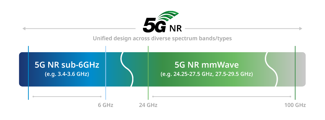
The frequency bands in which the 5G NR operates are normally divided into two broad categories: sub-6 GHz and millimeter wave (mmWave) as shown in the following Figure 1. For instance, the sub-6 GHz band including 3.4–3.6 GHz is popular due to its reliability, higher penetration ability, low propagation loss among other advantages, thus making it fit for wide-area mobile communication and power-efficient wireless communication links [6]. On the other hand, the mmWave bands are capable of high speeds, but their operations are hampered by issues like high path losses, coverage range and susceptibility to blockages. From the above, the complementarity of the bands reveals the need for an antenna system that is able to offer stability in the sub-6 GHz band while at the same time extending wideband operations. Wideband antennas that work on frequencies above the sub-6 GHz frequency range will be able to offer multiple wireless technologies within one small size antenna [7][8].
Apart from this, the Ultra-Wideband (UWB) spectrum has been paid a lot of attention in the frequency band of 3.1 GHz to 10.6 GHz, which can be applied in high data rate transmission, low consumption, and positioning. As illustrated in Figure 2, the UWB spectrum exists with other available wireless services like Wireless Fidelity (Wi-Fi), Bluetooth, Global Positioning System (GPS), and Personal Communication Services (PCS), and hence effective spectrum allocation and interference control are crucial design factors [9]. The UWB has a wide frequency spectrum, making it suitable for short-range communication systems and radar imaging, and for indoor positioning and localization systems. Thus, next-generation wireless devices would benefit greatly by having designs of antennas which can cover both UWB and nearby frequency ranges (e.g., 2.712 GHz) [10].
The microstrip antennas-based planar antennas have been one of the best choices in the field of wideband application because of its flat profile design, ease of manufacture, PCB compatibility, and low cost [11]. In particular, the microstrip-fed planar slot antennas exhibit an excellent bandwidth capability compared to the regular patch antennas while maintaining structural simplicity [12]. However, despite the advantages, a typical planar antenna is associated with several disadvantages of narrow bandwidth, lower gains, and radiation efficiency, especially when size limitations need to be considered. To overcome this problem, more advanced designs should be implemented for the planar antennas [13][14].
Many of the improvement techniques have been suggested in the literature in order to overcome the shortcomings listed above. The integration of a parasitic director element proves to be a quite effective technique for boosting gain and directivity of an antenna through the concentration of its radiated energy into the direction needed. The use of Frequency Selective Surfaces (FSS) helps control the propagation of electromagnetic waves and, therefore, improves gain and radiation parameters [15][16]. Similarly, mushroom-like structure of Electromagnetic Bandgap (EBG) finds a wide application in the process of controlling surface waves and enhancing radiation efficiency and mutual coupling of elements [17][18]. Furthermore, the special electromagnetic properties of the metamaterial-based structures make them effective in the process of increasing the band width, achieving miniaturization, and improving impedance matching [19]. Finally, the inclusion of an antenna array plan into the design adds gain to it and makes it possible to change the direction of the beam, an indispensable feature for any modern wireless system [20]. Most importantly, the MIMO technology turned out to become the basis of contemporary communication infrastructure because it increases the capacity of a communication channel while minimizing the influence of the multipath fading on the diversity performance [21][22].
This research paper presents a systematic method of improving the performance of antennas through the application of an extended version of a miniaturized wideband planar slot antenna in a series of MIMO configurations. In the first step of the research process, a microstrip-fed planar slot antenna is designed and simulated using Ansys HFSS with a partial defected ground structure (DGS). Then, in the next stage, a 1×2 MIMO configuration is used to assess the basic performance related to diversity. Furthermore, in order to optimize isolation, reducing the effect of mutual coupling between adjacent elements, a 1×2 cross MIMO configuration has been considered through polarization diversity. Ultimately, in order to further increase capacity and performance, a 1×4 MIMO configuration has been designed and analyzed. The design of the antenna system uses DGS technology, along with parasitic directors in order to obtain wide impedance bandwidth, high gain, and stable radiation pattern within the operating frequency from approximately 2.7–12 GHz. It is believed that the designed antenna system has great potential for use in modern broadband applications, especially UWB and 5G communications below 6 GHz.
Figure 1. 5G NR spectrum for Sub-6 GHz and mmWave bands
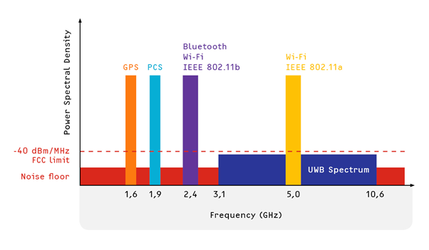
Figure 2. UWB spectrum and coexisting wireless systems
LITERATURE SURVEY
Many researches have been carried out over the past years concerning the design of wideband and MIMO antennas in order to cater to the demands of the current wireless communication technologies. Various techniques have been proposed to boost the performance of the antenna with respect to its bandwidth, gain, isolation, and radiation efficiency, and they include DGS, parasitic elements, metamaterials, and improved MIMO techniques. They all serve to ensure that the existing microstrip antenna is able to overcome the current shortcomings, thus making it possible for the antenna to be used in ultra-wideband and sub-6 GHz band. Some of the most significant pieces of literature are cited below.
In addition, the researchers (M. S. Khan et al.) proposed designing an eight-element ultra-wideband antenna (UWB-MIMO) antenna in 2020, in which the authors used multi-element diversity and band-rejecting techniques in order to minimize mutual coupling and increase isolation, resulting in broadband operation between 2-12 GHz with high isolation greater than 17 dB and low ECC [23].
Sun and Li authors in (2021) have presented the design of a wideband slot coupled microstrip antenna, and for this purpose, the authors used a Reflector Plus Sidewall Structure (RPSS) to improve gain stability and radiation performance, and obtained better gain flatness with a frequency band range of 3.75-4.81 GHz [24].
According to the authors (L. C. Paul et al.) in (2022), a slotted plus shaped microstrip patch antenna with defected ground structure was designed by the authors, and the authors applied slotting and DGS technology to improve impedance bandwidth, whereby an impedance bandwidth of 2.67–5.23 GHz was achieved with maximum gain of about 4.65 dB [25].
According to the authors (A. Ali et al.) in (2022), a circularly polarized MIMO antenna was designed by the authors, and the authors utilized DGS and polarization diversity technology to improve isolation and axial ratio bandwidth, whereby a 36% bandwidth was realized with maximum isolation of −28 dB [26].
Kiani, S. H., et al. In (2023), the authors have developed and designed a compact UWB-MIMO antenna, and in their research, the authors have utilized the common radiator with slotting to improve the isolation performance, resulting in a wide operating frequency range of 2.3–11.5 GHz with improved isolation performance [27].
Tighilt, Y., et al. In (2023), the authors have developed and designed a wideband UWB-MIMO antenna based on the integration of metamaterial, and in their research, the authors have utilized the concept of CSRR-based metamaterials and parasitic element in order to enhance isolation and bandwidth, resulting in 3.1–10.6 GHz operating frequency range and improved isolation of more than −22 dB [28].
Phyo, Z. M., et al. In (2024), the authors have developed and designed a wideband circularly polarized MIMO antenna, and in their research, the authors have utilized parasitic elements and reflector structures in order to enhance bandwidth and gain, resulting in 46% bandwidth with gain of up to 5.39 dBi [29].
In this work paper, the authors (M. M. Hasan et al.) in (2024) have developed and designed a metamaterial-loaded MIMO antenna, in which metamaterial structures were employed to improve bandwidth, miniaturization, and diversity performance, and they attained 49% bandwidth with ECC less than 0.006 and high diversity gain [30].
In this paper, the authors (M. Salehi and H. Oraizi) in (2024) have proposed and designed a wideband MIMO antenna using metasurface loading, where gain and isolation were enhanced using the metasurface loading technique, and they have achieved high gain and wideband operation at sub-6 GHz frequencies for 5G applications [31].
In this paper, the authors (R. H. Elabd et al.) in (2025) have proposed and designed a wideband MIMO antenna with DGS technique, where isolation and radiation efficiency were improved using the DGS technique, and they have achieved wideband operation from 3 to 6.5 GHz with −53 dB isolation and 11.5 dBi gain [32].
The Authors (U. Banerjee et al.) in (2025) developed a design of MIMO antenna based on metamaterial concept that consists of four elements; here, the authors applied CSRR metamaterial and defected patch structures for the enhancement of isolation and diversity characteristics and achieved isolation of more than 23 dB and ECC of 0.0029 [33].
Authors (A. U. Asad Ullah et al.) in (2026) developed a design of UWB-MIMO antenna; here, the authors applied decoupling structures in their work for the purpose of achieving high levels of isolation and wide bandwidth characteristics in order to attain UWB range of 1.5-20 GHz with isolation above 25 dB [34].
The authors (K. V. Prasad et al.) in (2026) developed a design of DGS for wideband MIMO antenna; here, the authors utilized modified radiators and defected ground structure for the purposes of achieving wideband operation with good isolation characteristics, and hence, they attained wide bandwidth of 3.1-18 GHz range [35].
The authors (Gagandeep Kaur et al.) in (2024) proposed and designed a double-port UWB MIMO antenna using dielectric resonator antenna with defected ground structure, wherein the authors have used an innovative design (airplane-shaped ground and array formation) in order to increase the bandwidth and achieve good isolation among the antennas, and hence they achieved a wide range of bandwidth from 6.3 to 12.6 GHz with good isolation [36].
The authors (Muvvala Kalpana and R. Ramana Reddy) in (2024) proposed and designed a 2-port and 4-port MIMO UWB antenna by using a combination of slot-loaded circular patch antenna with defected ground structure, wherein the authors have used rectangular slot loading and defected ground structure to achieve a wideband coverage in terms of frequency ranging from 4 to 20 GHz with maximum gain of 6.9 dB [37].
Furthermore, Z. Zhang et al., in (2023), proposed the development of an antenna system based on four UWB MIMO antenna components, in which the authors applied defected ground structures (DGS) with parasitic branch components to increase isolation and reduce mutual coupling between antenna elements, which resulted in wideband operation ranging from 3 to 18 GHz with high isolation and MIMO performance enhancement [38].
As shown in the following Table 1, recent works on wideband MIMO antennas have used various approaches for enhancing their bandwidth, gain, isolation, and diversity performance. Such approaches have included defected ground structures, parasitic elements, metamaterial loadings, slotting, decoupling structures, and various MIMO topologies. While these investigations have managed to bring about significant progress, the comparison reveals that many existing designs are characterized by certain trade-offs between their compactness, wide impedance bandwidth, high gain, low mutual coupling, and complete diversity. Many times, only S-parameters, gain, isolation, and Envelope Correlation Coefficient (ECC) are considered when evaluating these antennas, but some other MIMO metrics including Diversity Gain (DG), Total Active Reflection Coefficient (TARC), Channel Capacity Loss (CCL), Mean Effective Gain (MEG), radiation efficiency, fabrication status, and validation measurements are not mentioned. There is therefore a clear research gap in realizing a small wideband MIMO antenna with stable gain, low correlation, good isolation, and balanced diversity. This study aims to fill this gap through progressive design of the antenna from a single optimized radiator,  MIMO, cross MIMO with 4 ports, and
  MIMO topology with DGS, parasitic directors, and a lens-like substrate.
Table 1. Summary of related wideband and MIMO antenna designs
Ref. No. | Authors | Year | Method | Obtained Results |
[23] | M. S. Khan et al. | 2020 | 8-element UWB-MIMO with diversity | 2–12 GHz, isolation >17 dB, low ECC |
[24] | W. Sun and Y. Li | 2021 | Slot-coupled antenna with reflector (RPSS) | Bandwidth: 3.75–4.81 GHz, improved gain stability |
[25] | L. C. Paul et al. | 2022 | Slotted patch with DGS | 2.67–5.23 GHz, gain ≈ 4.65 dB |
[26] | A. Ali et al. | 2022 | CP MIMO with DGS | ~36% bandwidth, isolation ≈ −28 dB |
[27] | S. H. Kiani et al. | 2023 | UWB-MIMO with slot radiator | 2.3–11.5 GHz, improved isolation |
[28] | Y. Tighilt et al. | 2023 | UWB-MIMO with metamaterial & parasitic elements | 3.1–10.6 GHz, isolation < −22 dB |
[29] | Z. M. Phyo et al. | 2024 | CP MIMO with parasitic + reflector | ~46% bandwidth, gain ≈ 5.39 dBi |
[30] | M. M. Hasan et al. | 2024 | Metamaterial-loaded MIMO | ~49% bandwidth, ECC < 0.006 |
[31] | M. Salehi and H. Oraizi | 2024 | Metasurface-based MIMO | High gain, wideband sub-6 GHz |
[32] | R. H. Elabd et al. | 2025 | DGS-based MIMO antenna | 3–6.5 GHz, isolation ≈ −53 dB, gain 11.5 dBi |
[33] | U. Banerjee et al. | 2025 | Metamaterial + defected patch MIMO | Isolation > 23 dB, ECC ≈ 0.0029 |
[34] | A. U. Asad Ullah et al. | 2026 | Compact UWB-MIMO with decoupling | 1.5–20 GHz, isolation > 25 dB |
[35] | K. V. Prasad et al. | 2026 | DGS-based wideband MIMO | 3.1–18 GHz, stable gain |
[36] | G. Kaur et al. | 2024 | DRA MIMO with DGS | 6.3–12.6 GHz, improved isolation |
[37] | M. Kalpana and R. R. Reddy | 2024 | Slot-loaded DGS MIMO | 4–20 GHz, gain ≈ 6.9 dB |
[38] | Z. Zhang et al. | 2023 | UWB-MIMO with DGS + parasitic elements | 3–18 GHz, enhanced isolation |
PROPOSED METHODOLOGY
The design of the proposed antenna array system was carried out using a systematic multi-stage design procedure, focusing on achieving wideband frequency coverage, high gain, and diversity. This design method involves five stages, which include the design and optimization of a single antenna element followed by the scaling up of that single antenna element into different MIMO arrangements. Each of these stages makes a significant contribution towards the electromagnetic behavior of the proposed antenna array system.
Phase 1: Design and Optimization of Single Antenna Element
The design procedure starts with the design of a microstrip-fed planar slot antenna, incorporating partial Defected Ground Structure (DGS). The proposed antenna design employs the FR-4 substrate material because of its cheapness and applicability for use in the wireless environment. The design starts with the development of the basic structure, which consists of the radiating slot, microstrip feed, and partially defected ground plane. In addition, the design of the radiating slot starts with the use of the classical transmission-line approach; therefore, the first step in the development of the radiating slot involves obtaining the dimensions from the microstrip antenna formulae. Incorporation of the DGS is meant to ensure improved impedance matching and wider bandwidth through modification of current distribution in the ground plane. The design and analysis procedures are carried out through electromagnetic field simulation in Ansys HFSS. This entails optimization of the antenna performance in terms of impedance and radiation through modification of important geometrical parameters.
Phase 2: Gain Enhancement Using Directors and Lens-Shaped Structure
Having obtained an acceptable wideband response in the initial antenna design, the next step in further improvement is the inclusion of parasitic directors and the shaping of the substrate to a lens-like form. Parasitic directors are positioned in front of the radiating element so as to direct electromagnetic waves towards the forward direction for better performance in terms of gain and directivity. The distance between directors and their dimensions are optimized such that they couple constructively with the radiating element without deteriorating impedance matching. Moreover, the substrate is reshaped to have a lens form so as to facilitate wavefront collimation and minimize diffraction effects at the edges.
Phase 3: Design of 1×2 MIMO Antenna Configuration
For assessing the performance of the diversity, the single antenna element which has been optimized is extended to a MIMO structure by using 1×2 MIMO. Two same antennas are placed close to each other but keeping an optimal distance for minimizing size as well as coupling. Performance of MIMO antenna is determined based on S-parameters, isolation, and coupling between two antennas. Partial DGS is responsible for the reduction in surface waves propagation along with the minimization of the effect of coupling between antennas.
Phase 4: Cross-Configured 4-Port MIMO Antenna
In order to additional improve in the isolation and decrease mutual coupling further, a cross-type configuration of 4-Port MIMO is suggested. In this configuration, the orientation of the antennas is at right angles to one another. The reason for this design choice is to ensure that there is polarization diversity in the system. With this setup, the electromagnetic interference between the antennas is greatly reduced by avoiding any overlap of the currents and fields.
Phase 5: Design of 1×4 MIMO Antenna Configuration
Finally, the antenna configuration is expanded to include a 1×4 MIMO antenna system to further boost the system capacity and performance. The four antennas have been configured such that they maintain an optimal arrangement with regard to distance and orientation. Such a configuration allows the system to achieve maximum channel capacity, gain diversity and radiation coverage, thus making it more applicable in wireless high data rate communication applications. With the application of DGS and parasitic directors, the antenna can still retain its optimal impedance matching and gain characteristics.
ANTENNA DESIGN AND SIMULATION
In this section, the design and simulation of the proposed antenna system is presented based on the following phases: methodology section. The design, optimization of one antenna element, and gain enhancement using parasitic directors, and the use of a lens-like structure, is the basic structure and development of the antenna. The optimized element is then cascaded to a MIMO configuration, followed by a cross-configured 4-Port MIMO configuration with increased isolation and diversity performance, and finally, cascaded to a MIMO configuration to increase system capacity and radiation coverage. The antenna is modeled and analysed in Ansys HFSS in each phase to study the impedance matching, gain, isolation, and overall electromagnetic properties of the antenna.
Design and Optimization of Single Antenna Element
The antenna design process begins with the using of conventional rectangular microstrip patch, that is selected to be the reference structure to determine the initial dimensions of the radiator. Although the final antenna is transformed into a slot-based wideband configuration, the classical patch model provides a reliable analytical foundation and appropriate initial impedance behaviour before introducing bandwidth-enhancement modifications.
The antenna is implemented based on the low-cost FR-4 substrate with a relative permittivity of  , loss tangent
  , and height
  . For a selected fundamental resonant frequency
  , the patch width
  is calculated using the fundamental transmission-line model as presented in [32]:
| 
| (1) |
where  is referring to the speed of light in free space. The effective dielectric constant
  that appeared due to the fringing effect at the radiating edges, is determined by the following equation [39]:
| 
| (2) |
Furthermore, due to the fringing-field effect, the effective resonant length becomes greater than the physical patch length. The effective length  is given by [39]:
| 
| (3) |
The extension in length  caused by fringing fields is calculated as [40]:
| 
| (4) |
Finally, the actual length of the patch of the antenna ( ) can be calculated by means of the follwing Equation (5) [40]:
| 
| (5) |
Reference dimensions for the rectangular patch are determined based on the classical transmission line model considering the design frequency  which presented previously. Patch width is chosen based on higher radiation efficiency, whereas the effective dielectric constant takes into consideration the influence of the fringing fields near the patch edge. Based on that, the effective resonant length is determined and a correction factor is used to determine the actual patch length. Formulas used for calculation are presented in the following Table 2.
Table 2. Geometrical parameters of the initial antenna configuration.
Main Part | Design Quantity | Notation | Numerical Value |
FR-4 substrate | Dielectric constant | 
| 4.4 |
Substrate height |
| 1.6 mm |
Top radiating patch | Calculated patch width |
| 13.04 mm |
Effective dielectric constant |
| 3.781 |
Effective resonant length |
| 11.02 mm |
Edge-extension length |
| 0.718 mm |
Final physical patch length |
| 9.58 mm |
Bottom defected ground section | Central rectangular slot area | 
| 
|
Short branch length of L-shaped DGS | 
| 4.66 mm |
Short branch width of L-shaped DGS | 
| 0.8 mm |
Long branch length of L-shaped DGS | 
| 11.6 mm |
Long branch width of L-shaped DGS | 
| 1.9 mm |
As for the excitation of the designed antenna, it can be done using a microstrip feed line since it has a planar shape that makes the fabrication simple, together with its easy incorporation into printed circuit board technology. Wideband impedance matching is attained using the proposed feed line in a modified stepped L-shape with a rectangular coupling section. The design of this feed enhances electromagnetic coupling and facilitates stable wideband operation. Further improvement of the design can be achieved through the use of an optimization method in Ansys HFSS. In such a manner, the design parameters undergo a slow parametric modification starting with a basic reference antenna of rectangular patch type and modifying the shape of the radiating element, feeding structure, and ground plane. Modification of those parameters increases effective electrical lengths and provides a smooth impedance transition, thus ensuring improved wideband behavior. The final design structure is depicted in Figure 3.
Antenna performance will be assessed by means of simulation of the reflection coefficient and surface currents. Both the reflected energy and currents provide insight into the evolution of the optimized shape of the reference antenna through the series of geometric alterations that lead to excitation of various resonance modes, merging all these resonances together, which provides better stability of wideband impedance characteristics and radiation properties. After optimization of the radiator shape, a modified bow-tie-shaped radiator having sawtooth contours will be proposed; the latter provides larger radiation area and a more extended surface current distribution that adds new resonances and increases efficiency of electromagnetic coupling with the DGS layer. To provide better directionality of radiated waves and antenna gain, three parasitic directors will be added, as depicted in Figure 4.
The directors have been arranged in an optimized manner to ensure that constructive coupling is obtained along with efficient forward radiation without compromising the impedance behavior of the antenna. The incorporation of directors also ensures that the aperture size is increased while the surface current is distributed and backward radiation is reduced. This ensures better gain performance as well as the stability of the radiation pattern within the bandwidth range. Moreover, the substrate material is also modified to resemble a lens-like shape to provide better collimation of the wavefronts while reducing edge diffractions to ensure a uniform phase distribution over the radiating aperture area.
Figure 3. Proposed antenna inside HFSS simulation environment
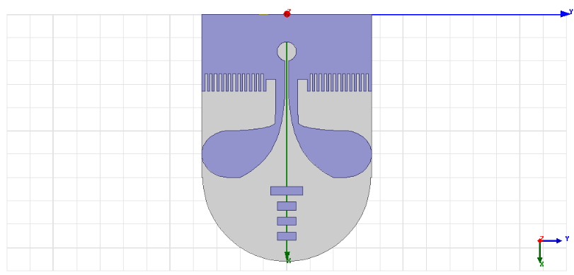
Figure 4. Proposed antenna with parasitic directors and lens-shaped substrate
Design of 2×1 MIMO Antenna Configuration
After design and optimization of the single radiator, which entails dimensions adjustments, adding of the parasitic director, and modification of the substrate into a lens shape, the optimized radiators are combined to form a 1 x 2 MIMO configuration, as shown in Figure 5.
At this stage, two identical antennas are placed adjacent to each other, utilizing the principle of mirroring in order to ensure symmetry in the structure as well as maintaining comparable electromagnetic properties between the two ports. The move from a single antenna to two antennas in the MIMO system is aimed at enhancing diversity and boosting capacity while still maintaining the wideband capabilities obtained from the single antenna design.
The geometry of MIMO antenna geometry is designed by locating both the optimal elements with an appropriate spacing, referred to as  . The spacing is chosen wisely so as to ensure optimal size while keeping mutual coupling low. If the width of the optimized antenna is
  , the total width for MIMO can be represented as:
| 
| (6) |
where is represents the separation between the adjacent antenna elements. The total length of the configuration remains approximately equal to the length of the single optimized antenna, provided that both elements are aligned along the same axis. The mirrored arrangement helps maintain current symmetry and supports comparable input characteristics at both ports.
Each individual antenna element is energized separately using a microstrip line with an impedance of 50 . The radio-frequency characteristics of the proposed MIMO configuration are analyzed using the scattering parameters. The reflection parameters of the two antennas are defined by
  and
and  , whereas the mutual coupling between the two antennas is expressed by
  and
and  . For the successful operation of MIMO technology, an antenna with good impedance matching at the two ports and low mutual coupling between the adjacent antennas is required.
The isolation between two antenna elements is estimated based on the transmission parameter S-Parameter, in which smaller values of  imply less interaction among electromagnetic fields and better isolation between two ports. Moreover, the ECC has been employed to characterize the diversity gain offered by the design. Using the S-parameters, ECC is formulated as [43]-[46]:
| 
| (7) |
where  denotes the complex conjugate. A low ECC value indicates weak correlation between the ports and confirms good diversity characteristics.
The DG of the MIMO antenna can be estimated from the ECC by using the following mathematical expression [47][48]:
| 
| (8) |
The above-given parameter shows the degree to which improvement in signal reliability is achieved using diversity techniques. As another metric for validating the MIMO broadband response, the TARC can also be taken into account, which is defined as follows [49]–[51]:
| 
| (9) |
TARC is used to evaluate the overall reflection performance of the antenna when multiple ports are excited simultaneously.
As far as the optimization part goes, the  MIMO antenna array design is optimized within Ansys HFSS by means of adjusting the distance between the two antennas, the alignment of the mirrored design, and the interaction between the two elements in terms of their shared ground planes. Such optimization will be done to achieve low coupling, keep the impedance bandwidth wide enough, and provide consistent radiation performance. Given the fact that the two radiating elements come from a design of an optimized antenna, the proposed MIMO antenna array design has the potential of inheriting its broadband performance, high gain, and radiation properties, in addition to diversity and multiport capability.
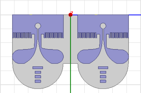
Figure 5. Geometry of the proposed 1×2 MIMO antenna
Cross-Configured 4-Port MIMO Antenna
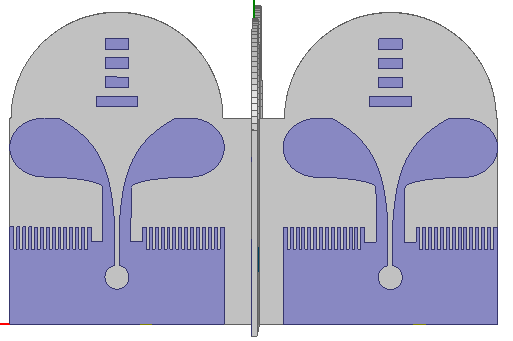
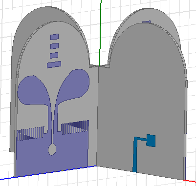
In order to increase the isolation of the proposed multiport antenna, the designed radiator was then placed in a cross-shaped 4-port MIMO antenna setup as depicted in Figure 6. This setup ensures that the placement of the antenna elements is perpendicular to each other to ensure that there would be a polarization diversity. The key idea behind this design is the minimization of the mutual coupling effects, which is caused by the minimum overlapping of the current paths of the adjacent ports. The cross formation was chosen to offer a convenient compromise between small physical dimensions, wideband performance, port isolation, and diversity performance. Port excitation is achieved individually through a 50 Ω microstrip feed line, but the spacing and orientation of the elements are altered in the Ansys HFSS simulation to ensure impedance matching and minimize coupling over the working band. The defected ground structure is also useful in ensuring that the current distribution on the ground plane is controlled, and the parasitic directors facilitate forward radiation. This means that the cross configuration for the 4-port MIMO design should enhance isolation and diversity performance while retaining the wideband performance of the single optimized antenna. This can be seen from the results section based on S-parameter measurements, gain, envelope correlation coefficient, diversity gain, total active reflection coefficient, and current analysis on the surface.
| 
|
- Front View
| - Side View
|
Figure 6. Proposed cross-configured 4-Port MIMO antenna
The geometry of the cross-configured 4-Port MIMO antenna is established by maintaining a controlled spacing between the two orthogonally arranged elements. If the optimized separation between the elements is denoted by  , then the overall spacing is selected to satisfy the compact design requirement while ensuring weak electromagnetic interaction. In the present design, the separation between the two antenna elements is fixed at
  . Accordingly, the overall dimensions of the cross-configured structure can be expressed as follows:
| 
| (10) |
| 
| (11) |
where and  denote the width and length of the optimized single antenna element, respectively, and is the separation distance between the two crossed elements.
Each antenna element is excited through an independent 50 microstrip feed line. The electromagnetic performance of the proposed cross-configured MIMO structure is evaluated using the scattering parameters, where and  denote the reflection coefficients of Ports #1 and #2, respectively, while and represent the mutual coupling between the two antenna elements. Owing to the orthogonal placement of the radiators, the electromagnetic field interaction between the elements is significantly reduced, resulting in lower transmission coefficients and improved port isolation. The diversity performance of the proposed antenna is further assessed using the ECC, as given in the previous Equation (7). A low ECC value indicates weak correlation between the two ports and confirms effective diversity operation. In addition, the corresponding DG is calculated using Equation (8). Therefore, by combining the optimized single antenna element with an orthogonal structural arrangement and an inter-element separation of
  , the proposed cross-configured 4-Port MIMO antenna achieves enhanced isolation, reduced mutual coupling, and improved diversity performance without the need for additional decoupling structures.
Design of 4×1 MIMO Antenna Configuration
After validating the performance of the designed single-element, MIMO, and cross-configured 4-Port MIMO antennas, the design is further extended to develop the structure of the  MIMO configuration in order to enhance channel capacity, diversity performance, and radiation coverage. The proposed MIMO antenna is formed by arranging four identical optimized antenna elements in a compact layout, as shown in Figure 7. Each element is derived from the previously optimized single antenna structure, including the dimensional refinement, parasitic directors, and lens-shaped substrate profile, so that the wideband and gain-enhancement characteristics are preserved in the multi-element configuration.
In the proposed structure, the four antenna elements are positioned with suitable spacing and orientation to achieve a balance between compact size and reduced mutual coupling. The overall dimensions of the MIMO configuration can be determined according to the arrangement of the antenna elements and the inter-element spacing. If the element spacing is denoted by  , the total array dimensions are calculated based on the same geometrical design procedure adopted in the previous MIMO configurations. The spacing is selected carefully to suppress electromagnetic coupling between adjacent ports while maintaining a practical and compact antenna footprint.
Each antenna element is excited through an independent 50 microstrip feed line. The electromagnetic behaviour of the MIMO antenna is characterized using the scattering parameters, where the diagonal terms  represent the reflection coefficients of the four ports, while the off-diagonal terms describe the mutual coupling between the antenna elements. Good MIMO performance requires low reflection coefficients within the desired operating band together with high isolation between all adjacent and non-adjacent ports.
To evaluate the diversity characteristics of the proposed MIMO antenna, the ECC is calculated using Equation (7) for each port pair. Likewise, the DG is calculated by means of the same Equation (8), whereas the TARC value is obtained based on the same formulation concept discussed earlier for multiport excitation. The above-mentioned parameters are crucial for establishing low levels of signal correlation, efficient diversity operation, and stable impedance characteristics in the 4-port configuration. In addition to ECC and DG, the quality of the  MIMO antenna system can also be verified via its CCL. The aforementioned parameter is critical for estimating the information carrying capacity of the MIMO structure. A low value of the Channel Capacity Loss means more efficient signal transmission with minimum losses associated with correlation and coupling effects. In addition, the MEG can be used to estimate the reception performance of each antenna element under multipath propagation conditions. Through the implementation of the optimized antenna in a MIMO configuration, the suggested design ensures enhanced diversity gain, greater channel capacity, and extended spatial coverage without sacrificing the wideband impedance response and consistent radiation behavior of the individual antenna.
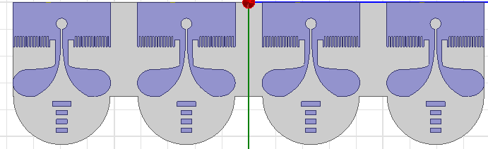
Figure 7. Geometry of the proposed MIMO antenna
RESULTS AND DISCUSSION
In this section, the simulated results of electromagnetic performance for the presented antenna configurations by Ansys HFSS software are given and explained. Firstly, the optimal design of single band antenna is analyzed in terms of impedance bandwidth, reflection coefficient, gain response, and radiation pattern to show the impact of the partial defected ground structure, parasitic directors, and the lens-shaped substrate. Afterward, the same analysis will be expanded on MIMO, 4-port cross MIMO, and MIMO antenna configurations to evaluate the effects of multi-element placement on impedance matching, mutual coupling, isolation, gain and diversity performance. It is intended to provide numerical results, along with the physical explanations and the trade-off among the improvements in the gain, size reduction, and diversity performance. Moreover, the results are compared to previous studies to indicate the benefits of the presented antennas in terms of wideband operation, low correlation, improved isolation, and suitability for UWB, sub-6 GHz 4G/5G, IoT, sensing and high-data rate wireless communication systems. Since the current study is based on simulations, the findings will be discussed in light of practical considerations, and future fabrication and experimental measurement is planned.
Results for Single Antenna
Next, the simulated reflection coefficient of the reference antenna is analyzed as the starting point for impedance characteristics analysis before carrying out the final optimization of the design. The −10 dB impedance bandwidth of the reference antenna is achieved between 3.25 GHz to 11.6 GHz, as illustrated in Figure 8, with the absolute bandwidth of 8.35 GHz. It is evident that the reference antenna is designed in such a way that it can support broadband operations. There are many resonant frequencies within the frequency range, especially around 8.7 GHz and 10.7 GHz where good impedance matching is achieved. In this regard, resonances are due to the interactions between microstrip feed, the radiating slot, and partial DGS structure which increase the effective current paths. Therefore, the reference antenna presents the best starting point for further optimization of the antenna structure, including changing the radiator shape, adding the parasitic director element, and shaping the substrate into lens form. Nevertheless, the figures presented in this section have been obtained using HFSS simulation.
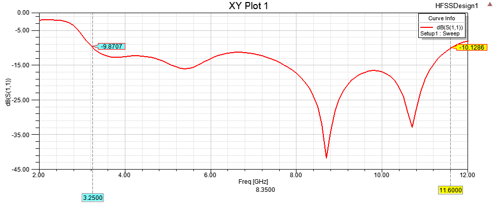
Figure 8. Return loss of the reference single antenna
Once the parametric optimization and structure modifications have been done, there will be a notable improvement in the impedance performance, which is evident in Figure 9. There will be an improvement in the -10dB impedance bandwidth performance by extending the bandwidth from 2.72GHz to 12GHz. These modifications include the reshaping of the radiators, feed line modifications, modification of the ground plane, addition of the parasitic director loading, and also the lens-shaped substrate configuration.
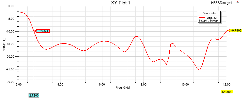
Figure 9. Return loss of the optimized single antenna
As a result, due to the wide operation frequency range of the proposed antenna design, three frequencies of 6.7 GHz, 8.7 GHz, and 10.7 GHz were selected to observe the behavior of gain in lower, middle, and higher parts of the operating frequency band. For the reference antenna design, the simulation results yield 4.75 dBi, 5.28 dBi, and 5.98 dBi as the maximum gain values at 6.7 GHz, 8.7 GHz, and 10.7 GHz frequencies, respectively. Upon implementing the optimization procedures, which include adding bow-tie inspired radiators, partial defected ground structure, parasitic directors, and lens-like substrate, the gains increase to 5.53 dBi, 6.79 dBi, and 6.21 dBi, respectively, at those same frequencies, as illustrated in Figure 10 to Figure 12. The increased gains indicate that the added directors facilitate forward radiation, whereas the lens shaped substrate helps in reducing edge diffraction and improving field concentration. Furthermore, the optimized design demonstrates a lower back-lobe level and more stable directional radiation pattern at selected frequencies. In this way, the proposed antenna design represents an improved wideband gain design and could be used as a good radiator for applications such as UWB, sub-6 GHz 4G/5G, IoT, sensing, and high data rate wireless communications.
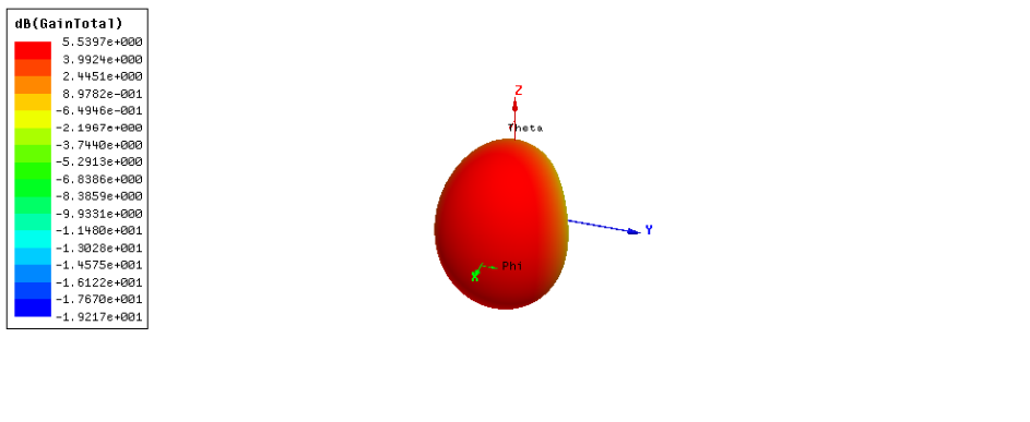
Figure 10. 3D gain plot of the reference antenna at 6.7 GHz
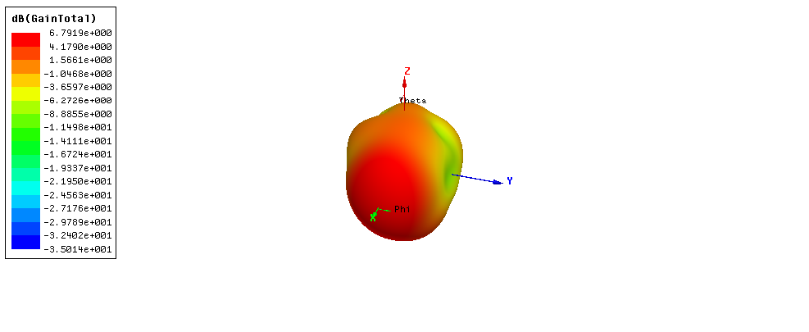
Figure 11. 3D gain plot of the reference antenna at 8.7 GHz
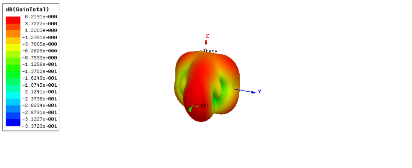
Figure 12. 3D gain plot of the reference antenna at 10.7 GHz
Results for MIMO Configurations
The simulated results of the proposed MIMO antenna designs which comprise of , cross-configured 4-Port MIMO, and designs will be presented in this subsection. The configurations are analysed by the performance of each configuration as measured by S-parameters, isolation and other diversity parameters to determine the impact of element layout on overall antenna behaviour. The obtained results are employed to check the applicability of the suggested MIMO structures in the application of wideband wireless communication.
Results for MIMO
The simulation results obtained for the MIMO antenna under consideration show that the optimized unit element can retain its wideband performance characteristics even when it is extended into a two-port structure. As seen from Figure 13, the reflection coefficients and demonstrate a similar behavior pattern staying within the −10 dB region for the common matched frequency range. The reason for such similarity lies in the mirror symmetry of the two identical radiating elements, ensuring similar current distributions at both ports. Moreover, the values of transmission coefficients and also stay low throughout the operation frequency band, suggesting sufficient isolation and minimal electromagnetic interaction between the nearby antennas. This proves that the design of the partial defected ground structure and inter-element distance is effective in minimizing the surface current coupling and maintaining the wideband nature of the individual antenna. In addition, the similarities between the values of and confirm the reciprocal and symmetric nature of the MIMO antenna design. In general, the findings prove the adequacy of the MIMO antenna in providing good impedance matching, compactness, and low mutual coupling.
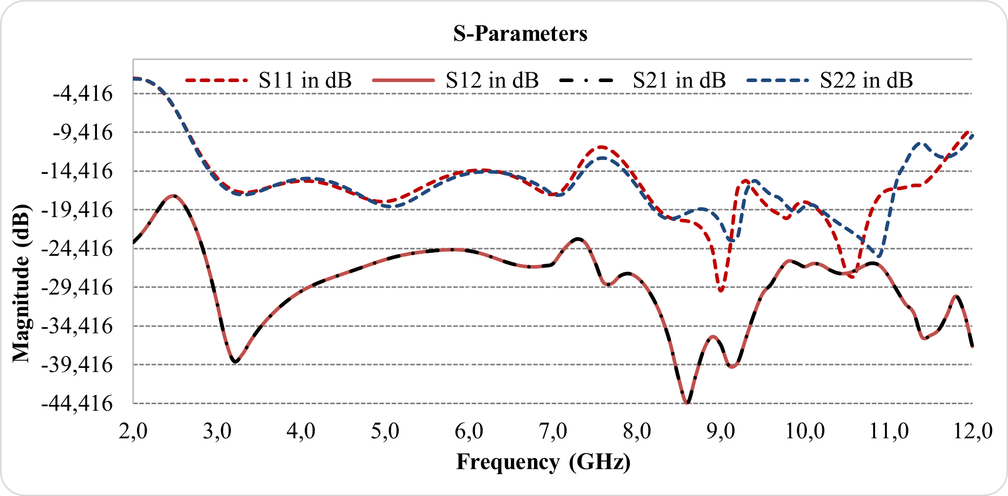
Figure 13. Simulated S-parameters of the proposed MIMO antenna
To further evaluate the diversity performance of the proposed MIMO antenna, the ECC, DG, and TARC were calculated from the simulated S-parameter results, as summarized in Table 3. The obtained values show that the two antenna ports have very low correlation within the common matched band. The worst-case ECC within this band is 0.0038 at 2.7 GHz, while the maximum ECC over the full simulated frequency range is 0.0691 at 2.2 GHz. These values are well below the commonly accepted limit of 0.5 for practical MIMO systems, indicating weak signal correlation and effective diversity behavior.
The corresponding DG remains close to the ideal value of 10 dB, with a minimum value of 9.9999 dB within the matched band and 9.9761 dB over the full simulated range. This confirms that the proposed MIMO configuration can improve link reliability under multipath propagation conditions. In addition, the best TARC value reaches approximately −22.80 dB at 9.1 GHz, which indicates favorable active impedance matching when both ports are excited simultaneously. Completely, the simulated results confirm that the proposed MIMO antenna achieves wideband matching, acceptable isolation, low envelope correlation, and nearly ideal diversity gain. These characteristics make the design suitable for UWB systems, sub-6 GHz 4G/5G communication, IoT devices, wireless sensing platforms, and short-range high-data-rate links. However, these findings are based on HFSS simulation, and prototype fabrication with measured S-parameters, gain, radiation pattern, and efficiency will be required in future work to confirm the practical performance of the design.
The gain performance analysis was conducted for the proposed MIMO antenna operating at 6.7 GHz, 8.7 GHz, and 10.7 GHz, which are lower, middle, and higher frequencies from the broad operating bandwidth range, respectively. According to Figure 14 to Figure 16, the 3D gain simulation results of the designed MIMO antenna show that directional radiations are achieved with field concentrations in the selected frequencies. The maximum gain values are 9.26 dBi, 9.94 dBi, and 8.88 dBi at 6.7 GHz, 8.7 GHz, and 10.7 GHz, respectively. It is believed that the gain enhancement of the proposed design is due to the effect of the optimized geometry of the radiating element, parasitic elements, lens-like substrate, and two-element MIMO configuration on the radiation characteristics of the antenna. While the gain performance is high within the selected frequencies, it mst be noted that the results presented in this study are simulated. Therefore, experimental gain and radiation performance analyses must be considered in the future.
Table 3. Diversity performance of the proposed MIMO antenna
Parameter | Value | Frequency / Condition |
Common matched band | 2.7–11.8 GHz |  dB dB
|
Worst-case ECC in matched band | 0.0038 | at 2.7 GHz |
Maximum ECC over full range | 0.0691 | at 2.2 GHz |
Minimum DG in matched band | 9.9999 dB | within 2.7–11.8 GHz |
Minimum DG over full range | 9.9761 dB | at 2.2 GHz |
Best TARC |  dB dB
| at 9.1 GHz |
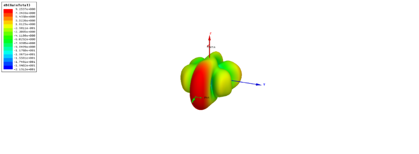
Figure 14. 3D gain plot of the proposed  MIMO antenna at 6.7 GHz
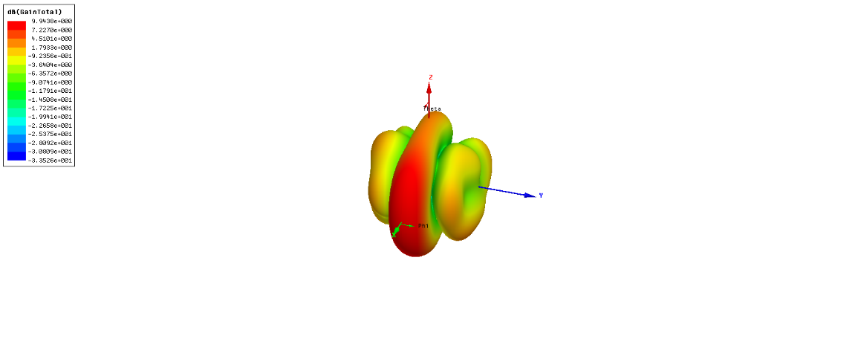
Figure 15. 3D gain plot of the proposed MIMO antenna at 8.7 GHz
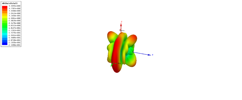
Figure 16. 3D gain plot of the proposed MIMO antenna at 10.7 GHz
Results for 4-Port MIMO
The simulated S-parameter results of the proposed cross-configured 4-port MIMO antenna are presented in Figure 17. For clarity, only the representative parameters , , and  are shown, where describes the input matching behavior, while and represent the mutual coupling between adjacent and non-adjacent antenna elements, respectively. It can be observed that the antenna maintains a wide impedance response, with remaining below the
  dB level over a broad frequency region, which confirms acceptable matching performance for the excited port.
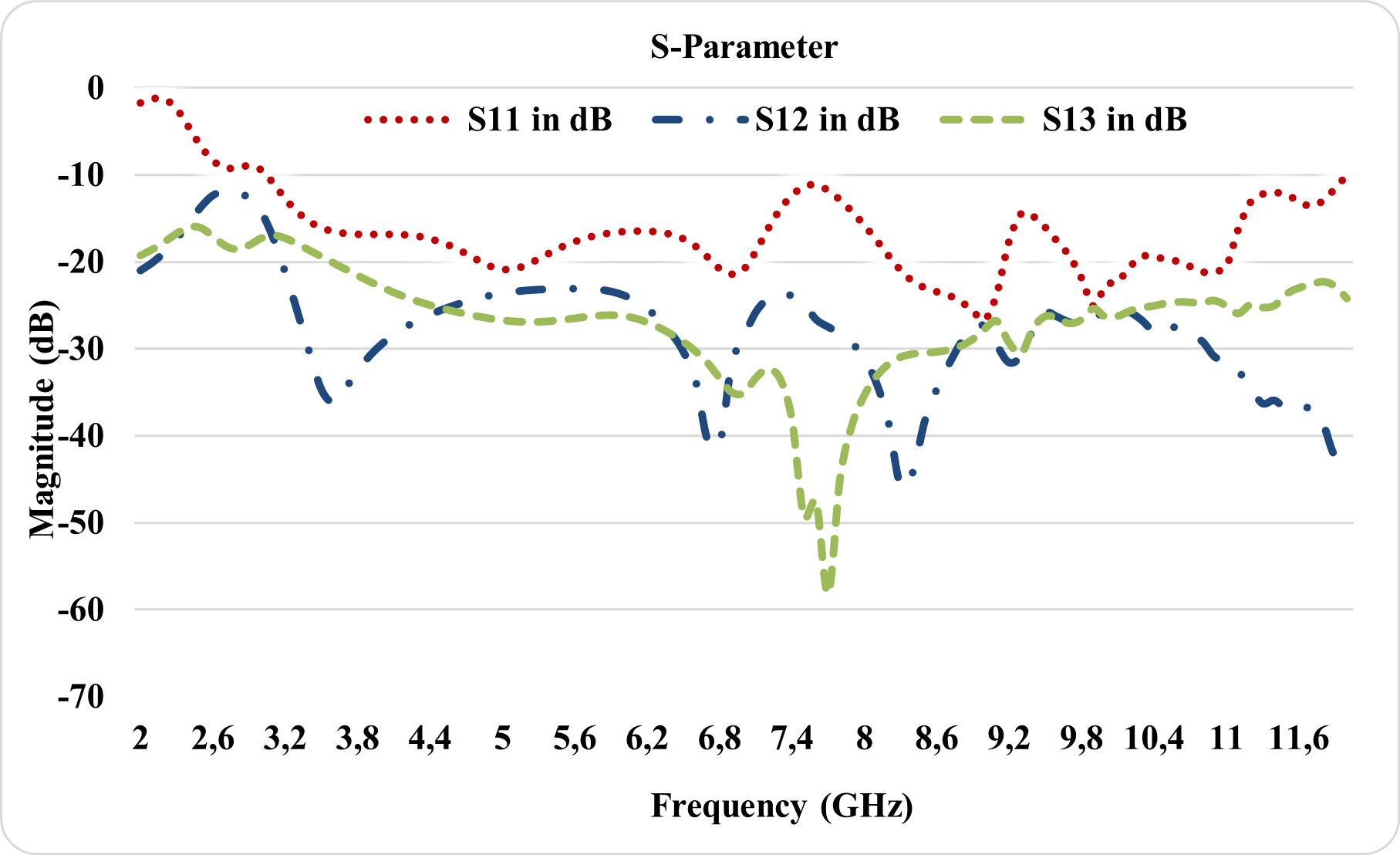
Figure 17. Cross-configured 4-port MIMO S-parameters
The isolation characteristics of the proposed cross-configured 4-port MIMO antenna show favorable behavior across the operating band, as illustrated by the representative S-parameter results in Figure 17. The coupling coefficients and generally remain below −20 dB over most of the frequency range, indicating weak electromagnetic interaction among the antenna elements. Stronger isolation is observed around the middle region of the band, where and reach deeper minima. This behavior confirms the role of the orthogonal arrangement in reducing mutual coupling through polarization diversity and lower surface-current overlap. In addition, the lower values of compared with in several frequency regions indicate that the non-adjacent elements are less coupled than the adjacent elements, which is consistent with the physical layout of the antenna. These results confirm that the proposed cross-configured arrangement improves port isolation while preserving wideband impedance matching, making it suitable for broadband MIMO operation. The gain performance was also evaluated at 6.7 GHz, 8.7 GHz, and 10.7 GHz to represent the lower, middle, and upper regions of the operating band, as shown in Figure 18 to Figure 20. The simulated 3D gain patterns demonstrate stable directional radiation with a clear forward main lobe and acceptable side-lobe behavior at the selected frequencies. This improvement can be attributed to the combined effect of the cross-oriented MIMO layout, parasitic directors, and lens-shaped substrate, which help concentrate the radiated field in the forward direction while maintaining the wideband response. Therefore, the proposed cross-configured 4-port MIMO antenna provides a useful balance between high gain, improved isolation, and diversity performance for UWB systems, sub-6 GHz 4G/5G networks, IoT devices, wireless sensor networks, and short-range high-data-rate wireless links. However, these findings are based on HFSS simulation, and experimental measurements are required in future work to validate the practical gain, radiation pattern, and isolation performance.
Furthermore, the diversity performance of the developed cross-configured 4-port MIMO antenna was considered through its ECC, DG, and TARC characteristics. From the results presented in Table 4, it can be confirmed that the designed configuration offers lower correlations between the radiating elements while keeping an acceptable diversity performance within the desired frequency range. The low values of ECC ensure no or minimal interaction between the ports and also show port independence, whereas the DG is still near to the ideal case. Moreover, TARC analysis results prove good active matching behavior for multiport excitation. It is important to state that all these performance parameters confirm satisfactory broadband operation of the cross-configured 4-port MIMO antenna design.
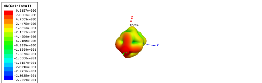
Figure 18. Gain of the cross-configured 4-port MIMO antenna at 6.7 GHz
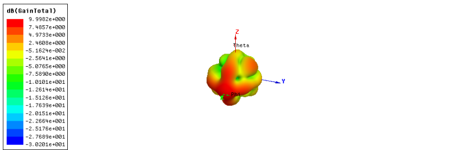
Figure 19. Gain of the cross-configured 4-port MIMO antenna at 8.7 GHz
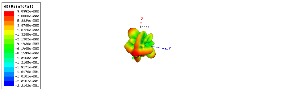
Figure 20. Gain of the cross-configured 4-port MIMO antenna at 10.7 GHz
Table 4. Cross-configured MIMO metrics
Parameter | Value | Condition |
Adjacent-port ECC | 
| within matched band |
Non-adjacent-port ECC | 
| within matched band |
Minimum DG |  dB dB
| within matched band |
Best TARC |  dB dB
| at 8.4 GHz |
Results for 1×4 MIMO
This section contains the simulation results of the designed MIMO antenna with respect to impedance matching and mutual coupling at all four ports. The objective of the analysis is to check if it is possible to keep wideband characteristics even after making an extension of the optimized antenna by arranging it in a four-element configuration. It is so because MIMO has elements that are adjacent, intermediate, and distant to each other.
The representative S-parameter behaviors of the suggested MIMO antenna are demonstrated using , , , and  in Figure 21 to eliminate excessive curve overlap in order to make figures more readable. Parameter refers to the input reflection coefficient of the excited port, whereas , , and indicate coupling among the adjacent, intermediate, and farthest antenna elements, respectively. It is demonstrated in the simulation results that is lower than −10 dB in a wide range of operating frequencies, which shows that the system configuration can maintain acceptable wideband impedance matching after antenna elements are incorporated. Moreover, the coupling parameters are relatively low in the considered band, suggesting that there is not much electromagnetic interference between the ports. The lowest value of coupling is usually achieved for since the associated elements are farther from each other, while is higher than others since adjacent elements are close together.
Generally, from the obtained S-parameter analysis, it is clear that the suggested MIMO antenna design offers a proper trade-off among multiport compactness, broad bandwidth impedance matching, and satisfactory isolation among the ports. All these factors justify the feasibility of this design for broadband MIMO wireless communications where spatial diversity and multiport capability are essential. Nevertheless, since the above results have been obtained through an HFSS simulation process, the fabricated antenna prototype needs to be tested through vector network analyzer and radiation analysis in future research developments.
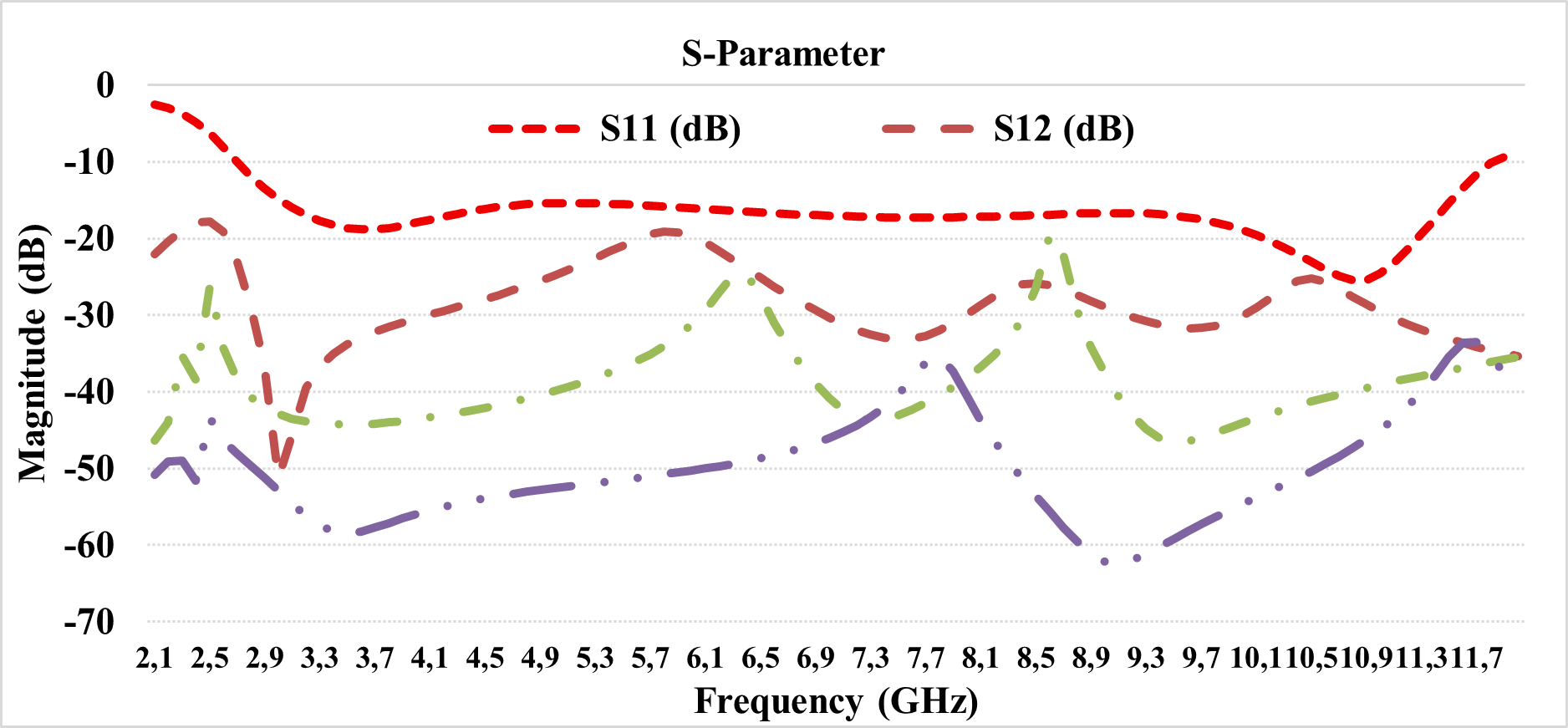
Figure 21. Representative S-parameters of the proposed MIMO antenna
The three-dimensional gain characteristics of the proposed 1×4 MIMO antenna were investigated at the operating frequencies of 6.7 GHz, 8.7 GHz, and 10.7 GHz, as shown in Figure 22 to Figure 24, respectively. These figures illustrate the spatial radiation performance of the antenna array and provide a clear indication of the gain distribution at the selected resonant frequencies.
As shown in Figure 22, the 3D gain pattern at 6.7 GHz demonstrates that the antenna is capable of radiating effectively at the lower operating band. The radiation distribution is stable, although the achieved gain is lower compared with the previous antenna designs. This reduction is mainly related to the transformation of the antenna structure into a compact MIMO configuration, where the close placement of four radiating elements increases the interaction between elements and affects the maximum radiated power.
At 8.7 GHz, as illustrated in Figure 23, the antenna still exhibits a satisfactory gain distribution with relatively more focused radiation behavior when compared to the one observed in the low-frequency band. Despite having a lower gain level compared to those in the previously discussed configurations, the radiation plot indicates that the antenna performs adequately in the mentioned frequency band. It is reasonable to conclude that the reduced gain level may arise from the trade-off caused by the inclusion of MIMO into the design.
The simulated 3D gain pattern of the proposed MIMO antenna is shown in Figure 24 and corresponds to 10.7 GHz, which lies at the high end of the operational band. From the figure, it is clear that the antenna is capable of sustaining directional radiation even at this high frequency, although the gain obtained is less than that of the individual, MIMO, and cross-polarized 4-port MIMO configurations. The reason for the decrease in the gain value is due to the compact configuration of the four elements, as more electromagnetic interactions exist between them at the smaller separation, resulting in the redistribution of radiated power between different ports and decreasing the radiation strength of individual antennas.
While the MIMO antenna has low gain, it offers some significant benefits to multiport wireless antennas. The fact that there are four elements means that the MIMO antenna will have high spatial diversity and greater chances of receiving independent multipath signals, which is vital for increasing the reliability of links in MIMO. As such, the performance of this particular arrangement cannot solely be based on its gain but should also consider diversity factors such as envelope correlation coefficient, diversity gain, total active reflection coefficient, channel capacity loss, and average effective gain among others. In essence, the MIMO antenna configuration involves a compromise between tight integration and gain on the one hand and diversity, multiple ports, and broadband MIMO operation on the other hand.
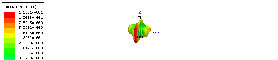
Figure 22. Gain of the cross-configured MIMO antenna at 6.7 GH
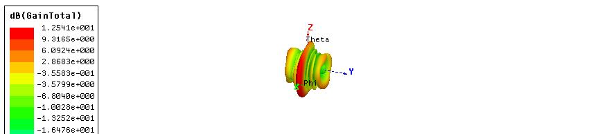
Figure 23. Gain of the cross-configured MIMO antenna at 8.7 GHz
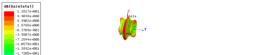
Figure 24. Gain of the cross-configured MIMO antenna at 10.7 GHz
Therefore, the reduction in gain is compensated by the improvement in overall MIMO functionality. The configuration can enhance signal reception in multipath environments, reduce the probability of signal fading, and improve communication reliability. In addition, using four antenna elements increases the possibility of spatial diversity and provides better coverage compared with a single-element or simpler antenna configuration. This makes the design more suitable for compact multi-band wireless applications where size reduction and multi-element integration are required.
The diversity characteristics of the proposed MIMO antenna were further evaluated using the ECC, DG, and the TARC. The obtained results, summarized in Table 5, confirm that the proposed configuration provides very low correlation among the antenna elements over the matched operating band. In particular, the adjacent-port ECC remains below 0.0021, while the non-adjacent-port ECC stays below 0.0010, indicating weak mutual correlation and effective port independence. Correspondingly, the diversity gain remains nearly ideal, with a minimum value of about 9.9999 dB. In addition, the best TARC reaches approximately  dB at 10.8 GHz, which indicates favorable active matching performance for the proposed multiport antenna. Overall, the presented results verify that the proposed MIMO configuration achieves excellent diversity behavior and stable wideband multiport performance.
Table 5. Diversity metrics of the proposed MIMO antenna.
Parameter | Value | Condition |
Adjacent-port ECC | 
| within matched band |
Non-adjacent-port ECC | 
| within matched band |
Minimum DG | 
| within matched band |
Best TARC | 
| at 10.8 GHz |
The comprehensive simulated performance comparison of the presented MIMO antenna arrays is provided in Table 6. It can be seen from the results that adding more elements to the optimized single antenna to form various MIMO configurations enhances the antenna diversity properties without compromising the broadband impedance characteristics. The gain of both MIMO and cross configuration of 4-port MIMO antennas is maximized for chosen representative frequencies of 6.7 GHz, 8.7 GHz, and 10.7 GHz, thus proving the positive influence of multi-element design, parasitic directors and field concentration on the radiation properties of the antennas. The cross configuration of 4-port MIMO antenna array demonstrates the highest gain value among all other antennas, as well as minimum ECC and nearly optimal DG.
However, in the case of the 1×4 MIMO antenna, its gain values are lower when compared with the single, MIMO, and cross-configured 4-port MIMO antennas. The decrease in the gain values is mostly associated with the compact four-element combination, in which interaction among the elements, power redistribution through various ports, and increased currents could decrease the radiation level of the radiators. Nonetheless, the MIMO antenna has excellent diversity properties, ECC close to zero, DG near the ideal values, and satisfactory multiport operation. Thus, this configuration can be considered for applications in which spatial diversity and multi-stream communication are more crucial than high gain per port. Summarizing, it becomes clear that all suggested configurations have their own advantages: the single antenna allows obtaining a compact wideband radiator, the MIMO antenna has increased gain and basic diversity capabilities, the cross-configured 4-port MIMO antenna has the best gain-isolation characteristics, and the MIMO antenna is beneficial from the standpoint of multiport diversity for broad band communication systems. As the analysis above was performed by using HFSS simulation, the future work should include the actual fabrication and verification of the results experimentally.
Table 6. Performance comparison of the proposed antenna configurations
Antenna Design | Bandwidth (GHz) | Gain at 6.7 GHz (dB) | Gain at 8.7 GHz (dB) | Gain at 10.7 GHz (dB) | ECC | DG (dB) | TARC (dB) |
Reference single antenna | 2.72–12.0 | 5.5397 | 6.7919 | 6.2191 | — | — | — |
MIMO | 2.7–11.8 | 9.25 | 9.94 | 8.88 | 
| 9.9999 |
|
Cross-configured 4-port MIMO | Wideband | 9.31 | 9.99 | 9.89 |
| 9.9997 |
|
MIMO | Wideband | 1.253 | 1.254 | 1.261 |
| 9.9999 |
|
CONCLUSION
This paper presented a simulation-based wideband planar antenna system using a microstrip-fed slot radiator with a partial defected ground structure, parasitic directors, and a lens-shaped substrate. The proposed design was systematically developed from an optimized single antenna element to MIMO, cross-configured 4-port MIMO, and MIMO configurations in order to investigate the trade-off among impedance bandwidth, gain, isolation, and diversity performance. The optimized single antenna achieved a simulated −10 dB impedance bandwidth of 2.72–12.0 GHz, with peak gains of 5.54 dBi, 6.79 dBi, and 6.21 dBi at 6.7 GHz, 8.7 GHz, and 10.7 GHz, respectively. The MIMO configuration preserved wideband operation over 2.7–11.8 GHz and improved the gain to 9.25 dBi, 9.94 dBi, and 8.88 dBi at the same representative frequencies. It also achieved a worst-case ECC of 0.0038, a minimum DG of 9.9999 dB, and a best TARC of −22.80 dB, confirming good diversity and active matching performance. Among the investigated configurations, the cross-configured 4-port MIMO antenna provided the best overall radiation performance, with gains of 9.31 dBi, 9.99 dBi, and 9.89 dBi at 6.7 GHz, 8.7 GHz, and 10.7 GHz, respectively. This improvement confirms the effectiveness of the orthogonal arrangement in reducing mutual coupling through polarization diversity and lower surface-current overlap. Although the MIMO antenna showed lower gains of 1.253 dBi, 1.254 dBi, and 1.261 dBi, it provided strong diversity characteristics, including adjacent- and non-adjacent-port ECC values below 0.0021 and 0.0010, respectively, with a minimum DG of 9.9999 dB. This result indicates a clear trade-off between gain reduction and improved multiport diversity in the compact four-element configuration. completely, the proposed antenna family offers a balanced solution for wideband operation, gain enhancement, port isolation, and MIMO diversity performance, making it a promising candidate for UWB systems, sub-6 GHz 4G/5G communication, IoT terminals, wireless sensing platforms, indoor access points, and other broadband wireless applications. However, the present study is limited to HFSS simulation. Future work will focus on prototype fabrication, vector network analyzer measurement of S-parameters, anechoic-chamber validation of gain and radiation patterns, radiation-efficiency evaluation, fabrication tolerance analysis, and complete multiport experimental verification to confirm the practical applicability of the proposed designs.
REFERENCES
- M. Pant and L. Malviya, “Design, developments, and applications of 5G antennas: A review,” International Journal of Microwave and Wireless Technologies, vol. 15, no. 1, pp. 156–182, Feb. 2023, https://doi.org/10.1017/S1759078722000095.
- T. Raj, R. Mishra, P. Kumar, and A. Kapoor, “Advances in MIMO antenna design for 5G: A comprehensive review,” Sensors, vol. 23, no. 14, p. 6329, 2023, https://doi.org/10.3390/s23146329.
- A. Patnaik, and M. V. Kartikeyan, “Compact dual and triple band antennas for 5G-IOT applications,” International Journal of Microwave and Wireless Technologies, vol. 14, no. 1, pp. 115–122, Feb. 2022, https://doi.org/10.1017/S1759078721000301.
- N. Kishore and A. Senapati, “5G smart antenna for IoT application: A review,” International Journal of Communication Systems, vol. 35, no. 13, 2022, https://doi.org/10.1002/dac.5241.
- S. Khan, T. Mazhar, T. Shahzad, A. Bibi, W. Ahmad, M. A. Khan, M. M. Saeed, and H. Hamam, “Antenna systems for IoT applications: A review,” Discover Sustainability, vol. 5, Nov. 2024, https://doi.org/10.1007/s43621-024-00638-z.
- D. G. Arnaoutoglou, T. M. Empliouk, T. N. F. Kaifas, M. T. Chryssomallis, and G. Kyriacou, “A review of multifunctional antenna designs for Internet of Things,” Electronics, vol. 13, no. 16, Aug. 2024, https://doi.org/10.3390/electronics13163200.
- A. De, B. Roy, A. Bhattacharya, and A. K. Bhattacharjee, “Bandwidth-enhanced ultra-wide band wearable textile antenna for various WBAN and Internet of Things (IoT) applications,” Radio Science, vol. 57, no. 2, 2022, https://doi.org/10.1029/2021RS007315.
- A. Desai, M. Palandoken, J. Kulkarni, G. Byun, and T. K. Nguyen, “Wideband flexible/transparent connected-ground MIMO antennas for sub-6 GHz 5G and WLAN applications,” IEEE Access, vol. 9, pp. 147003–147015, 2021, https://doi.org/10.1109/ACCESS.2021.3123366.
- B. S. Taha and H. M. Marhoon, “Simulation and manufacturing of modified circular monopole microstrip antenna for UWB applications,” International Journal of Advances in Applied Sciences, vol. 10, no. 1, pp. 70–78, 2021, https://doi.org/10.11591/ijaas.v10.i1.pp70-78.
- K. V, K. C and T. G, "Design and Analysis of an FSS-Based Wearable MIMO Antenna for Wireless Body Area Networks in Telemedicine Applications," 2026 International Conference on Computing, Communication, Control and Cyber-Physical Systems (I5CPS), Karaikal, Puducherry, India, 2026, pp. 1-6, 2026, https://doi.org/10.1109/I5CPS67958.2026.11452575.
- B. Ashvanth and B. Partibane, “A high gain UWB antenna with ENG metasurface as a biosensor for cancer diagnosis,” Journal of Computational Electronics, vol. 25, 2026, https://doi.org/10.1007/s10825-026-02537-0.
- M. Al-Qutbi and A. Abdu Ibrahim, “Performance improvement of a microstrip patch antenna using FSS superstrate and corporate-fed array for high-band 5G systems,” International Journal of Smart Control and Electrical Engineering Systems, vol. 1, no. 1, pp. 47–64, 2026, https://ijscees.org/index.php/pub/article/view/5.
- K.-H. Huang and Y.-S. Chen, “Slot-coupled fed 256-element planar microstrip array with beam stability for K-band water level sensing,” Sensors, vol. 25, no. 18, 2025, https://doi.org/10.3390/s25185904.
- V.-T. Nguyen and J.-Y. Chung, “Design of a planar antenna array with wide bandwidth and narrow beamwidth for IR-UWB radar applications,” Applied Sciences, vol. 12, no. 17, 2022, https://doi.org/10.3390/app12178825.
- A. Alsudani and H. M. Marhoon, “Performance enhancement of microstrip patch antenna based on frequency selective surface substrate for 5G communication applications,” Journal of Communications, vol. 17, no. 10, pp. 851–856, Oct. 2022, https://doi.org/10.12720/jcm.17.10.851-856.
- I. Troudi, C. Baccouch, B. Chibani et al., “Integration of frequency selective surfaces with MIMO antennas for enhanced performance in IoT and V2V communication systems,” Scientific Reports, vol. 15, 2025, https://doi.org/10.1038/s41598-025-19483-9.
- A. Alsudani and H. M. Marhoon, “Design and enhancement of microstrip patch antenna utilizing mushroom-like EBG for 5G communications,” Journal of Communications, vol. 18, no. 3, pp. 156–163, Mar. 2023, https://doi.org/10.12720/jcm.18.3.156-163.
- N. Qasem, H. M. Marhoon, and N. F. Abdul Malek, “A graphene-based rectangular-notched UWB antenna with reconfigurable notch,” International Journal on Engineering Applications, vol. 13, no. 3, pp. 222–232, 2025, https://doi.org/10.15866/irea.v13i3.24249.
- M. Q. Abdalrazak, A. H. Majeed, and R. A. Abd-Alhameed, “An analytical investigation on the performance of 1D and 2D antenna arrays for MM-wave modern communication systems,” Iraqi Journal of Information and Communication Technology, vol. 6, no. 2, pp. 78–88, 2023, https://doi.org/10.31987/ijict.6.2.254.
- F. Mehmood and A. Mehmood, “Recent advancements in millimeter-wave antennas and arrays: From compact wearable designs to beam-steering technologies,” Electronics, vol. 14, no. 13, p. 2705, 2025, https://doi.org/10.3390/electronics14132705.
- S. Kumar et al., “Metamaterial-based microwave absorbers: A critical review of design principles and emerging applications,” Discover Materials, vol. 6, p. 106, 2026, https://doi.org/10.1007/s43939-026-00588-5.
- S. Kumari and A. Hossain, “Comprehensive review on performance analysis for satellite communication MIMO over terrestrial communication MIMO,” International Journal of Satellite Communications and Networking, vol. 44, no. 4, pp. 445–463, 2026, https://doi.org/10.1002/sat.70035.
- A. Kumar et al., “Design of MIMO antenna for 6G applications supported by fractal geometry,” Scientific Reports, 2026, https://doi.org/10.1038/s41598-026-38312-1.
- M. S. Khan, A. Iftikhar, R. M. Shubair, A.-D. Capobianco, B. D. Braaten, and D. E. Anagnostou, “Eight-element compact UWB-MIMO/diversity antenna with WLAN band rejection for 3G/4G/5G communications,” IEEE Open Journal of Antennas and Propagation, vol. 1, pp. 196–206, 2020, https://doi.org/10.1109/OJAP.2020.2991522.
- W. Sun and Y. Li, “Gain stabilization method for wideband slot-coupled microstrip antenna,” IEEE Transactions on Antennas and Propagation, vol. 69, no. 12, pp. 8932–8936, Dec. 2021, https://doi.org/10.1109/TAP.2021.3097441.
- L. C. Paul, S. C. Das, T. Rani, S. M. Muyeen, S. A. Shezan, and M. F. Ishraque, “A slotted plus-shaped antenna with a DGS for 5G Sub-6 GHz/WiMAX applications,” Heliyon, vol. 8, no. 12, Dec. 2022, https://doi.org/10.1016/j.heliyon.2022.e12040.
- H. Ali, J. Illahi, M. M. Qadir, M. A. Khan, R. M. Ghoniem, and A. J. A. Al-Gburi, “Mutual coupling reduction through defected ground structure in circularly polarized, dielectric resonator-based MIMO antennas for sub-6 GHz 5G applications,” Micromachines, vol. 13, no. 7, 2022, https://doi.org/10.3390/mi13071082.
- S. H. Kiani et al., “An ultra-wide band MIMO antenna system with enhanced isolation for microwave imaging applications,” Micromachines, vol. 14, no. 9, 2023, https://doi.org/10.3390/mi14091732.
- Y. Tighilt et al., “Low-profile UWB-MIMO antenna system with enhanced isolation using parasitic elements and metamaterial integration,” Electronics, vol. 12, no. 23, 2023, https://doi.org/10.3390/electronics12234852.
- Z. M. Phyo, T. Fujimoto, and C.-E. Guan, “Wideband circularly polarized two-element MIMO antenna with polarization diversity,” IEICE Communications Express, vol. 13, no. 12, pp. 487–491, 2024, https://doi.org/10.1587/comex.2024COL0021.
- M. M. Hasan, M. T. Islam, T. Alam, P. Kirawanich, S. Alamri, and A. S. Alshammari, “Metamaterial loaded miniaturized extendable MIMO antenna with enhanced bandwidth, gain and isolation for 5G sub-6 GHz wireless communication systems,” Ain Shams Engineering Journal, 2024, https://doi.org/10.1016/j.asej.2024.103058.
- M. Salehi and H. Oraizi, “Wideband high gain metasurface-based 4T4R MIMO antenna with highly isolated ports for sub-6 GHz 5G applications,” Scientific Reports, vol. 14, 2024, https://doi.org/10.1038/s41598-024-65135-9.
- R. H. Elabd, A. J. A. Al-Gburi, and A. A. Megahed, “Compact circular MIMO antenna with defected ground structure (DGS) for improved isolation in 5G sub-6GHz mobile systems,” Results in Engineering, vol. 27, 2025, https://doi.org/10.1016/j.rineng.2025.105737.
- U. Banerjee, S. S. Pattanayak, A. K. Biswas, and S. Sahoo, “Design and analysis of a high-isolation metamaterial-inspired MIMO antenna with defected patch structures for improved sub-6 GHz band performance in 5G wireless applications,” Results in Engineering, 2025, https://doi.org/10.1016/j.rineng.2025.108280.
- A. U. Asad Ullah, O. K. Owais Khan, A. I. Adnan Iftikhar, S. K. Shahid Khan, and M. Dalarsson, “A highly compact two-port UWB MIMO antenna with enhanced performance and low mutual coupling for IoT applications,” Frontiers in Physics, vol. 14, 2026, https://doi.org/10.3389/fphy.2026.1704074.
- K. V. Prasad, S. Kadiyam, V. N. K. Rao, V. Kollipara, B. Alekhya, B. Madhavi, P. V. Kumar, J. Ravi, and H. G. Mohamed, “A novel DGS-integrated compact wideband modified cloverleaf MIMO antenna for multi-band wireless applications,” Wireless Personal Communications, 2026, https://doi.org/10.1007/s11277-026-11942-4.
- G. Kaur, R. K. Gangwar, and B. K. Kanaujia, “Dual port UWB MIMO dielectric resonator antenna (DRA) with airplane shaped defective ground plane (DGS) with improved isolation level,” Wireless Personal Communications, vol. 139, pp. 1225–1237, 2024, https://doi.org/10.1007/s11277-024-11664-5.
- M. Kalpana and R. Ramana Reddy, “Slotted circular patch MIMO antennas for multiband and UWB applications,” ARPN Journal of Engineering and Applied Sciences, vol. 19, no. 24, pp. 1484–1491, Jan. 2025, https://doi.org/10.59018/122482.
- T. Ding, H. Yang, Z. Chen, Z. Lin, B. He, and C.-Z. Han, “A 4-element UWB MIMO antenna system with high isolation performance,” Applied Computational Electromagnetics Society Journal, vol. 38, no. 10, 2023, https://doi.org/10.13052/2023.ACES.J.381007.
- R. Shafique et al., “Comparison of different feeding techniques for a patch antenna at an X frequency band to evaluate its quantitative impact on the antenna’s parameters,” Journal of Applied Research and Technology, vol. 18, no. 6, pp. 341–352, 2020, https://doi.org/10.22201/icat.24486736e.2020.18.6.1350.
- L. G. Ayalew and F. M. Asmare, “Design and optimization of pi-slotted dual-band rectangular microstrip patch antenna using surface response methodology for 5G applications,” Heliyon, vol. 8, no. 12, 2022, https://doi.org/10.1016/j.heliyon.2022.e12030.
- P. Ghewari and V. Patil, “Advancements in microstrip patch antenna design using nature-inspired metaheuristic optimization algorithms: A systematic review,” Archives of Computational Methods in Engineering, vol. 32, pp. 3687–3732, 2025, https://doi.org/10.1007/s11831-025-10254-3.
- A. Bansal and R. Gupta, “A review on microstrip patch antenna and feeding techniques,” International Journal of Information Technology, vol. 12, no. 1, pp. 149–154, 2020, https://doi.org/10.1007/s41870-018-0121-4.
- M. Darsono and A. R. Wijaya, “Design and simulation of a rectangular patch microstrip antenna for the frequency of 28 GHz in 5G technology,” Journal of Physics: Conference Series, vol. 1469, 2020, https://doi.org/10.1088/1742-6596/1469/1/012107.
- A. K. Singh and S. Pal, "Compact Self-Isolated Extremely Low ECC Folded-SIW-Based Slot MIMO Antenna for 5G Application," in IEEE Antennas and Wireless Propagation Letters, vol. 23, no. 1, pp. 194-198, Jan. 2024, https://doi.org/10.1109/LAWP.2023.3321065.
- A. Ahmad, D.-Y. Choi, and S. Ullah, “A compact two elements MIMO antenna for 5G communication,” Scientific Reports, vol. 12, 2022, https://doi.org/10.1038/s41598-022-07579-5.
- O. Elalaouy, M. El Ghzaoui, and J. Foshi, “Mutual coupling reduction of a two-port MIMO antenna using defected ground structure,” e-Prime-Advances in Electrical Engineering, Electronics and Energy, vol. 8, 2024, https://doi.org/10.1016/j.prime.2024.100557.
- J. MP, T. P. Surekha, and S. Kumar AJ, “Innovative designs and performance evaluation of super wideband MIMO antennas: A survey,” Nondestructive Testing and Evaluation, vol. 41, no. 2, pp. 635–666, 2026, https://doi.org/10.1080/10589759.2024.2447387.
- Y. Tighilt, C. Bensid, D. Sayad, S. Mekki, R. Zegadi, M. L. Bouknia, I. Elfergani, P. Singh, J. Rodriguez, and C. Zebiri, “Low-profile UWB-MIMO antenna system with enhanced isolation using parasitic elements and metamaterial integration,” Electronics, vol. 12, no. 23, 2023, https://doi.org/10.3390/electronics12234852.
- A. Perez-Miguel, H. Jardon-Aguilar, J. A. Tirado-Mendez, R. Gomez-Villanueva, R. Flores-Leal, and E. Fritz-Andrade, “An in-depth statistical analysis of the TARC parameter to evaluate the real impact of random phases in MIMO antennas,” Sensors, vol. 25, no. 13, 2025, https://doi.org/10.3390/s25134171.
- C. Güler and S. E. Bayer Keskin, “A novel high isolation 4-port compact MIMO antenna with DGS for 5G applications,” Micromachines, vol. 14, no. 7, 2023, https://doi.org/10.3390/mi14071309.
Ramy Abduimawjood Mohammed (Cross-Configured Wideband Multiple-Input Multiple-Output Antenna with Defected Ground Structure and Parasitic Directors for 2.7–12 GHz Ultra-Wideband and Sub-6 GHz Wireless Applications)