ISSN: 2685-9572 Buletin Ilmiah Sarjana Teknik Elektro
Vol. 8, No. 4, August 2026, pp. 1019-1033
Static-Slope Dynamics and Uncertainty of a Compact-Excavator Manipulator for Near-Ground Sensing
Pham Chi Thanh 1, Tran Ngoc Binh 1, Nguyen Xuan Chiem 2
1 Control, Automation in Production and Improvement of Technology Institute (CAPITI), Vietnam
2 Le Quy Don Technical University, Vietnam
ARTICLE INFORMATION |
| ABSTRACT |
Article History: Received 28 March 2026 Revised 02 June 2026 Accepted 28 July 2026 |
| 
Near-ground unexploded ordnance (UXO) sensing requires a mobile carrier that maintains a controlled detector air gap over uneven terrain. This paper develops a static-slope rigid-body baseline for a Bobcat E20-class mini excavator carrying a 15 kg VMF4-class payload on a self-leveling gimbal. The research contribution is a body-frame, parked-base formulation that separates arm-level Cartesian positioning from payload-level attitude stabilization and identifies which rigid-body terms change on a static slope. The four-DOF attachment is reduced to a planar three-DOF boom-stick-tool subsystem for line sweeping. A kinetic-energy argument and potential-energy differentiation show that, with parked chassis and body-fixed coordinates, the inertia and Coriolis/centrifugal terms retain their level-ground form, while only the gravity torque is recomputed from the rotated gravity vector and center-of-mass Jacobians. Evaluation combines static torque analysis, Monte Carlo propagation, computed-torque tracking, and runtime timing. At 10° pitch, the 95th-percentile end-effector uncertainty is 2.63-3.65 cm; at 15° pitch, the tested gravity-torque change reaches 322.66 Nm. In the Python reproducibility environment, gravity-only update takes 24.0 microseconds per sample, compared with 38.9 microseconds for full rigid-body term recomputation. The 5.7°-6.3° trigger is a heuristic gravity-bias indicator, not a stability or clearance guarantee. Results support lightweight slope-aware gravity recomputation, while hydraulic dynamics, friction, soil interaction, moving-base effects, embedded timing, and hardware validation remain future work. |
Keywords: Hydraulic Excavator Dynamics; Uncertainty Propagation; Static Slope Compensation; Computed-Torque Control; Chassis Attitude Estimation |
Corresponding Author: Nguyen Xuan Chiem, Le Quy Don Technical University, 236 Hoang Quoc Viet, Hanoi, Vietnam. Email: chiemnx@mta.edu.vn |
This work is open access under a Creative Commons Attribution-Share Alike 4.0 
|
Document Citation: P. C. Thanh, T. N. Binh, and N. X. Chiem, “Static-Slope Dynamics and Uncertainty of a Compact-Excavator Manipulator for Near-Ground Sensing,” Buletin Ilmiah Sarjana Teknik Elektro, vol. 8, no. 4, pp. 1019-1033, 2026, DOI: 10.12928/biste.v8i4.16278. |
INTRODUCTION
Humanitarian unexploded-ordnance (UXO) sensing requires a carrier that can move a detector close to the ground while maintaining a controlled and reproducible air gap. Compact hydraulic excavators are attractive for this role because they are rugged, mobile, and already designed to position tools over uneven terrain. In the present task, however, the bucket is replaced by a lightweight sensing payload rather than a digging tool. The excavator arm is therefore interpreted as a Cartesian positioning mechanism for the gimbal-center reference point, while the sensor module handles local payload attitude.
This arm-payload separation is important for the scope of the paper. The self-leveling payload acts on a much smaller inertia than the complete arm-chassis system, whereas the excavator attachment must compensate the gravity loading induced by a parked chassis slope. The paper therefore studies the rigid-body arm-level gravity and uncertainty problem first, before hydraulic dynamics, friction, soil interaction, or moving-base terrain following are added.
Hydraulic-excavator automation research now covers system-level autonomy and field demonstrations [1][2], data-driven excavation trajectory planning and inclination-displacement-based trajectory control [3], [7], mobile landmine-detection platforms [4], multibody excavator dynamics [5][6], heavy-duty hydraulic-manipulator modeling [33], robotic-excavator kinematic/constraint modeling [34], parameter identification [8][9], chassis-pose sensing [10], and moving-base road excitation in heavy machines [12], vibration modal analysis on level ground [60], and uneven-terrain locomotion for legged or whole-body systems [56],[58]. Recent control and planning work spans database-driven and model-inversion control [14]-[16], electro-hydraulic adaptive and sliding-mode control (SMC) for excavators [11],[17][18], together with related adaptive/fixed-time SMC developments for robotic manipulators [31][32], safety-barrier and disturbance-observer control [21], reinforcement learning for excavation tasks [19][20],[22],[48], hydraulic-envelope and regenerative-valve model predictive control (MPC) [23], pressure-feedback gain-scheduled MPC for boom-oscillation reduction [35], deadtime/regenerative-pipeline position control [29], task-oriented and hybrid trajectory planning [41][42],[47], minimum-jerk and time-jerk trajectory optimization for industrial and redundant robots [61][62], physics-informed and digital-twin trajectory pipelines [46],[49], passivity/impedance tracking [43], collaborative high-precision tracking [44], and constrained low-complexity tracking [45].
These studies address autonomy, digging, actuator-level control, or trajectory generation. A common assumption across nearly all of them — including the moving-base, pose-compensation, and uneven-terrain works [10],[12],[57] — is that the chassis is either level or that terrain enters only as a high-frequency disturbance to be rejected by feedback. Static tilt, however, alters the equilibrium gravity loading at each joint by an amount that depends on both pitch and arm posture, and does so even when the chassis is perfectly still. None of the cited works isolates this static decomposition of the inertia, Coriolis/centrifugal, and gravity terms for a compact excavator carrying a near-ground sensing payload with sparse manufacturer inertial data. This leaves a practical modeling gap: before adding hydraulics, friction, soil contact, or moving-base dynamics, it must be clear which part of the rigid-body model changes when the chassis is parked on a static slope, and how the remaining parameter and attitude uncertainty propagate to the sensing-point error.
Rather than proposing a new hydraulic controller, the research contribution is a static-slope rigid-body baseline for a compact excavator carrying a near-ground UXO sensing payload. The baseline separates arm-level Cartesian positioning from payload-level attitude stabilization, states the parked-base conditions under which the level-ground inertia and Coriolis/centrifugal terms can be reused, and quantifies how slope-dependent gravity loading and parameter/attitude uncertainty affect the sensing-point error. The intended role is not to replace hydraulic, friction-aware, or learning-based controllers, but to provide a reproducible gravity-compensation and uncertainty reference before those higher-fidelity effects are added.
The specific contributions are:
- A body-frame, parked-base static-slope formulation for the Bobcat E20 boom-stick-tool subsystem with a VMF4-class payload, which makes the chassis-attitude coupling explicit through a single constant rotation matrix rather than through any particular Euler-angle parameterization.
- A scope-bound Lemma 1 demonstrating that the inertia and Coriolis/centrifugal terms retain their level-ground form only under parked-base, body-fixed-coordinate assumptions, while the gravity term changes through the rotated gravity vector. The lemma fixes the cost of slope-aware compensation at a gravity-only update and locks the moving-base inertial terms explicitly out of scope.
- A Monte Carlo uncertainty analysis with bounded mechanical priors and Gaussian attitude-error priors, evaluated on a fully reproducible Python pipeline with bootstrap confidence intervals, which separates parameter-driven and attitude-driven contributions to the sensing-point error.
- A computed-torque rigid-body baseline that exposes the slope-gravity mismatch as a Cartesian tracking error on the order of half a centimetre under a perfectly known nominal model. Its role is to establish a lower bound on tracking error attributable to gravity modeling alone, before friction and valve dynamics are added; it is not claimed as a deployable hydraulic controller.
- A conservative gravity-torque sensitivity trigger derived from the normalized worst-case posture-grid deviation, reported as a heuristic indicator for enabling slope-aware gravity recomputation rather than as a stability margin or clearance threshold.
- METHODS
System Setup and Modeling Scope
The system is a Bobcat E20-class mini excavator whose standard bucket is replaced by a 15 kg Vallon VMF4-class sensing payload, mounting bracket, skid plate, and fasteners. The original four-DOF attachment model contains swing, boom, stick, and tool coordinates. For the line-sweeping sensing task considered here, swing is held fixed and the retained arm model is the planar three-DOF boom-stick-tool chain.
The payload re-parameterization is treated as a change in the distal link, not as an extra digging load added on top of the original bucket. The standard bucket mass is removed and the terminal mass is set to a nominal  = 15 kg, representing the VMF4-class sensor array, non-magnetic bracket, skid plate, fasteners, cabling, and the retained rod-side hardware required by the distal assembly. The boom and stick effective masses,
  and
and  , retain the structural-link and cylinder-allocation estimates used by the original model.
The E20 geometric and component assumptions are assembled from manufacturer specifications, parts/attachment references, and the operation manual [13],[24]-[26]; the resulting inertial quantities are retained as engineering estimates rather than hardware-identified parameters.
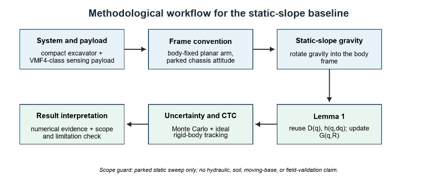
Before introducing the static-slope analysis, it is useful to outline how the modeling steps fit together. Figure 1 summarizes the workflow used in the remainder of this section and in Section 3, starting from system re-parameterization, proceeding through the parked-base lemma and the slope-aware gravity update, and ending with the rigid-body Monte Carlo and computed-torque analyses that produce the numerical results. The static-slope frame convention itself is introduced separately in Section 2.2.
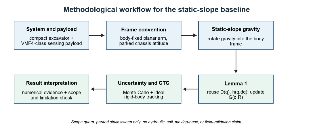
Figure 1. Methodological workflow for static-slope modeling, uncertainty propagation, and rigid-body tracking evaluation
Each block in Figure 1 carries explicit modeling commitments. Because those commitments narrow the scope of the static-slope claim — for example, the parked-base assumption, the planar reduction, and the deliberate exclusion of hydraulic actuator dynamics — they are collected in Table 1 as the assumption-versus-boundary structure used throughout the paper. Subsequent sections rely on Table 1 to keep all numerical claims within that scope.
Two assumption rows in Table 1 deserve particular emphasis. The parked-chassis condition is the structural reason that the inertia matrix and the Coriolis/centrifugal torque vector retain their level-ground form in Section 2.4. The planar arm chain restricts the analysis to the in-plane gravity components and lumps the lateral, roll-induced component into a constraint reaction outside the retained generalized coordinates. With those boundaries fixed, Table 2 collects the deterministic geometric and inertial parameters and the uncertainty priors that feed the numerical study.
The values in Table 2 are not claimed to be hardware-identified inertial parameters. They define a transparent engineering baseline for the revised static-slope study; the bounded priors in Section 2.5 are used to expose how sensitive the gravity and sensing-point quantities are to the remaining mass, CoM, payload, and attitude uncertainty.
Table 1. Modeling assumptions and scope boundaries
Assumption | Used in this paper | Boundary |
Parked chassis | Base roll/pitch are constant during a sweep; base translational velocity, angular velocity, and angular acceleration are zero. | Does not cover moving-base traversal, track slip, suspension compliance, or terrain-induced acceleration. |
Fixed swing | Swing is held constant in line-sweeping mode. | Out-of-plane dynamics and swing-brake capacity are not modeled. |
Planar arm chain | The boom-stick-tool subsystem is modeled in the body/swing xz plane. | Roll-induced lateral gravity is treated as a constraint reaction outside the planar generalized coordinates. |
Rigid links and lumped payload | The VMF4-class sensor, bracket, skid plate, and fasteners are represented by an equivalent terminal payload. | Gimbal actuator reaction torque and small gimbal center-of-mass shifts are not explicitly modeled. |
No soil contact load | The sensor operates near the ground without digging contact. | Digging resistance, soil compliance, and bucket-soil interaction are outside the scope. |
Ideal computed-torque surrogate | Computed-torque control is used to expose rigid-body gravity-model mismatch. | It is not a deployable hydraulic controller; valve dynamics, saturation, pressure dynamics, friction, and deadtime are deferred. |
Engineering uncertainty priors | Mass and center-of-mass errors are bounded priors; attitude errors are Gaussian priors. | Values are not hardware-identified on the current Bobcat E20-class platform. |
Table 2. Nominal geometric, inertial, and simulation parameters used in the paper.
Group | Nominal values | Use in the paper |
Geometry | Base horizontal offset 0.746 m; base vertical offset 0.551 m; boom length 1.620 m; stick length 1.190 m; tool/sensor-mount length 0.638 m. | Planar kinematic chain and center-of-mass Jacobians. |
Mass and CoM | Effective boom mass 119.285 kg; stick mass 51.290 kg; payload mass 15.0 kg; nominal CoM distances 0.729, 0.476, and 0.319 m. | Effective boom/stick/payload masses and nominal CoM locations. |
Joint limits | Boom: -20° to 60°; stick: -100° to 50°; tool: -120° to 60°. | Admissible posture grid for static torque and trigger analysis. |
Monte Carlo priors | Mechanical masses and CoM: bounded +/-5 percent; payload: normal with mean 15 kg and standard deviation 0.5 kg; attitude errors: normal with standard deviation 0.25°. | Uncertainty propagation at 10° pitch. |
Reference sweep | Start posture (20°,-80°,60°); end posture (45°,-35°,-10°); constant tool attitude with joint-angle sum equal to 0°. | Minimum-jerk CTC demonstration with constant planar tool attitude. |
Coordinate Frames and Static-Slope Convention
Figure 2 shows the frame convention used in the static-slope derivation. Notation follows a standard robotics convention: rotation matrices use uppercase italic symbols, vectors use lowercase italic symbols with frame superscripts, and scalar link parameters and scalar angles use italic scalar notation. Let  map a vector from the body frame {B} to the world frame {W}; then
  and
and  . The world
  axis is upward and
  . Positive pitch
  denotes a nose-up chassis rotation about the body
  axis, and positive roll
  denotes a right-hand rotation about the body
  axis. Because the parked-base result is written directly in terms of the constant rotation matrix , it does not depend on a particular Euler-angle parameterization. Let
  map a vector from the swing frame {S} to the body frame {B}. In the fixed-swing line-sweeping mode, the gravity vector projected into the swing frame is
| 
| (1) |
Thus the static attitude affects the retained planar arm only through the in-plane components of the rotated gravity vector. For the sign convention above, the body-frame in-plane gravity components are  before the fixed-swing projection.
Throughout the static-slope analysis, is constant in time and the swing coordinate is held fixed. The retained generalized coordinate vector is
| 
| (2) |
where the swing coordinate is fixed for line-sweeping operation. The sensor reference point is the gimbal-center or tool-point used for near-ground sweep planning; the local sensor module is assumed to stabilize payload attitude.
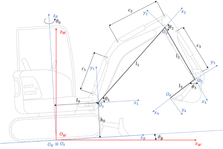
Figure 2. Compact-excavator sensing setup and static-slope frame convention
- Slope-Dependent Potential Energy and Gravity Torque
Let  denote the center-of-mass position of body
  expressed in the swing frame, and let
  be the corresponding translational Jacobian. The slope-dependent potential energy is
| 
| (3) |
Therefore, using the sign convention of the manipulator equation, the generalized gravity torque is
| 
| (4) |
The y-component of  produces no virtual work on the retained planar coordinates when the swing coordinate is locked and the center-of-mass trajectories remain in the swing plane. In this reduced model it is therefore interpreted as a lateral bearing or swing-lock reaction, whereas the in-plane components enter the generalized torques in (4).
Parked-Base Dynamics Lemma
The planar rigid-body model is written as
| 
| (5) |
In this study, the Coriolis/centrifugal contribution is reported as the torque vector  . When a matrix representation is needed,
  , where
  denotes one Christoffel-form realization associated with
  [27]. Because is not unique, the simulations use the torque vector as the primary quantity.
For readers less familiar with the manipulator equation, the three rigid-body terms have the following physical meaning in the present setting. The mass matrix collects the configuration-dependent kinetic-energy quadratic form of the three planar links and the lumped terminal payload; in the body-fixed swing frame, it depends only on the three joint angles and is independent of the chassis attitude, as shown in Section 2.4 below. The Coriolis and centrifugal torque vector collect the velocity-quadratic terms that arise from the time derivative of the mass matrix and the kinetic-energy partial derivative; in the parked-base configuration with body-fixed coordinates, it depends only on joint angles and joint rates, again independently of the chassis attitude. The generalized gravity torque is the only term that couples the chassis attitude into the manipulator equation: in the level-ground formulation it is the gradient of the potential energy taken with the world-vertical gravity vector, whereas in the static-slope formulation it is the gradient taken with the rotated gravity vector projected into the swing frame. The static-slope claim of this paper is precisely that, under the parked-base and body-fixed-coordinate assumptions stated in Table 1, the first two terms keep their level-ground functional form and only the third one is recomputed.
Lemma 1 (reuse of and under parked static tilt). Consider the planar boom-stick-tool generalized coordinates  expressed in the body-fixed swing plane. If the chassis is parked during the sweep, with
  and constant
  (3), then the kinetic energy of the planar chain depends only on and
  . Consequently, the inertia matrix and the Coriolis/centrifugal vector retain the same functional form as in the level-ground model. The gravity term changes because the potential energy uses the rotated gravity vector in (1).
Proof. With a parked base, every retained link velocity in the planar chain is generated only by the relative joint rates and the fixed link geometry. The constant rotation changes how the chain is embedded in the world frame, but it does not introduce base translational velocity, base angular velocity, or base angular acceleration into the kinetic energy. Therefore, the kinetic energy can be written as
as in the level-ground body-frame model. The Coriolis/centrifugal vector induced by is unchanged because it is obtained from derivatives of the same kinetic-energy metric with respect to . The potential energy is different because each link center-of-mass position is evaluated against in (3), so differentiation of (3) gives the slope-dependent gravity torque  .
.
This lemma is not claimed as a new general robotics theorem. It is the standard kinetic-energy/potential-energy separation specialized to a parked excavator on a static slope: and are generated by the kinetic-energy metric and do not depend on  , whereas is obtained from the potential energy. The lemma is stated explicitly to fix the coordinate convention, lock the moving-base terms out of scope, and justify the gravity-only software update. A detailed derivation is provided in Appendix A. If the base moves, additional inertial terms associated with base acceleration, angular velocity, and angular acceleration must be appended.
Uncertainty Propagation
The Monte Carlo analysis samples bounded mechanical priors and Gaussian attitude-estimation errors. Link masses and and center-of-mass locations  ,
,  , and
, and  are sampled independently from bounded engineering priors within ±5 percent of their nominal values. The terminal sensing payload is sampled as a normal variable with mean 15 kg and standard deviation 0.5 kg, and the pitch/roll attitude-estimation errors are sampled as zero-mean Gaussian variables with standard deviation chosen consistent with the post-filter accuracy reported for MEMS-IMU attitude estimators with bias compensation and complementary or robust adaptive filtering [51]-[53], that is 0.25°.
This bounded-prior treatment is consistent with model-based uncertainty and Monte Carlo analyses used in robotic systems [36][37], while the separate payload prior reflects the importance of payload uncertainty in manipulator trajectory performance [40].
The 0.25° prior reflects the post-filter accuracy reported for the ADIS16470 industrial MEMS IMU [28] under static or quasi-static conditions, and is consistent with extended Kalman, complementary, and robust adaptive filter performance reported in [51]-[53]. Three simplifications of this sensor model deserve explicit acknowledgment. First, the attitude error is treated as a time-invariant Gaussian prior rather than as a stochastic process with finite bandwidth, which is consistent with the parked-base scope but understates the impact of vibration- or motion-induced disturbances. Second, sensor latency is not propagated because the present analysis is static; under low-speed quasi-static traversal, an attitude estimator with bandwidth above the sweep rate is implicitly assumed, and the latency contribution would have to be added separately. Third, magnetic disturbance and chassis vibration that would arise from an operating hydraulic system are deferred together with the moving-base extension. These simplifications keep the uncertainty propagation aligned with the parked-base scope of Lemma 1, and they identify the IMU-side modeling refinements that must accompany the moving-base extension to remain self-consistent.
The journal results use  samples at nominal pitch 10° with seed 42. Relative gravity-torque mismatch is normalized by
  , and 95th-percentile confidence intervals are obtained by bootstrap resampling. Link lengths are held nominal; therefore, the Cartesian tip uncertainty reported here is driven mainly by attitude-estimation error, while mass and CoM priors mainly affect the gravity-torque statistics.
Computed-Torque Baseline
The computed-torque control (CTC) law is used as a rigid-body analytical surrogate:
| 
| (6) |
The tested reference preserves the planar tool-attitude constraint used by the sweep task. It is a fifth-order minimum-jerk interpolation over  between
  and
and  ; both endpoints satisfy
  , and the scalar interpolation preserves this linear constraint at every sample. In (6),
  and
and  ; under an exact rigid-body model, (6) yields
  . The simulated gains are
  and
and  , corresponding to critically damped nominal second-order error dynamics with natural frequency 20 rad/s. The ODE integration uses RK45 with relative tolerance
  , absolute tolerance
  , and maximum step 0.01 s.
Recent computed-torque-control studies have revisited efficient dynamic formulations and adaptive CTC variants [38][39], while other extensions learn the dynamics online or tune feedback gains with population-based search [54][55]. These extensions are not incorporated here, because the baseline is used only to expose the gravity-model mismatch under nominal parameters. The baseline is not a PID-only controller and is not a deployable hydraulic-valve controller. Hydraulic deadtime, pressure dynamics, pressure saturation, valve nonlinearities, and joint friction are excluded to isolate the gravity-model mismatch.
RESULTS AND DISCUSSION
Main Findings of the Present Study
The following check is a software self-consistency check, not an independent dynamics validation. Table 3 reports the maximum absolute differences obtained when the implemented , , and routines are evaluated at fixed and while the chassis pitch is varied.
Table 3. Implementation self-consistency under the parked-static formulation
Pitch (deg) | Inertia diff (kg m²) | Coriolis/centrifugal diff (N m) | Gravity torque diff (N m) |
0 | 0.000e+00 | 0.000e+00 | 0.00 |
5 | 0.000e+00 | 0.000e+00 | 93.25 |
10 | 0.000e+00 | 0.000e+00 | 201.07 |
15 | 0.000e+00 | 0.000e+00 | 322.66 |
Table 3 note. Evaluated at  and and  rad/s; the implemented and are independent of the pitch argument. This is not an independent Newton-Euler validation. rad/s; the implemented and are independent of the pitch argument. This is not an independent Newton-Euler validation. |
Key Numerical Findings
Table 4 condenses the numerical claims that are carried into the discussion. The table deliberately separates geometric projection error, uncertainty propagation, ideal rigid-body tracking, and the heuristic gravity-bias trigger so that these quantities are not interpreted as the same performance metric.
Table 4. Key numerical findings for the static-slope rigid-body baseline
Result | Verified value | Interpretation |
Mid-range boom gravity torque at 0° | 2009.0 N m | Level-ground value |
Mid-range boom gravity torque at 15° | 1684.2 N m | 16.2 percent reduction |
Tucked configuration gravity-torque change | 31.1 percent | Most sensitive tested posture |
Identical-command tip displacement at 10° | 0.6967 m | Geometric projection error, not tracking error |
MC p95 tip uncertainty at 10° | 2.63-3.65 cm | Uncertainty from parameter/attitude priors |
Flat-ground controller at 10° | 0.5375 cm max tip error | Nominal lower-bound dynamic mismatch |
Slope-aware controller at 10° | 0.0004 cm max tip error | Numerical-noise level under ideal nominal model |
10 percent slope-sensitivity trigger | boom 6.27°, stick 5.75°, bucket 5.74° | Gravity-torque sensitivity trigger only |
The 0.6967 m identical-command displacement is a geometric projection effect caused by applying the same joint command on a pitched chassis. It is not the closed-loop tracking error. The computed-torque results are therefore reported separately. Figure 3 visualizes the same static-gravity trend behind the first three entries of Table 4 and shows that the gravity-torque change depends on both pitch and arm posture.
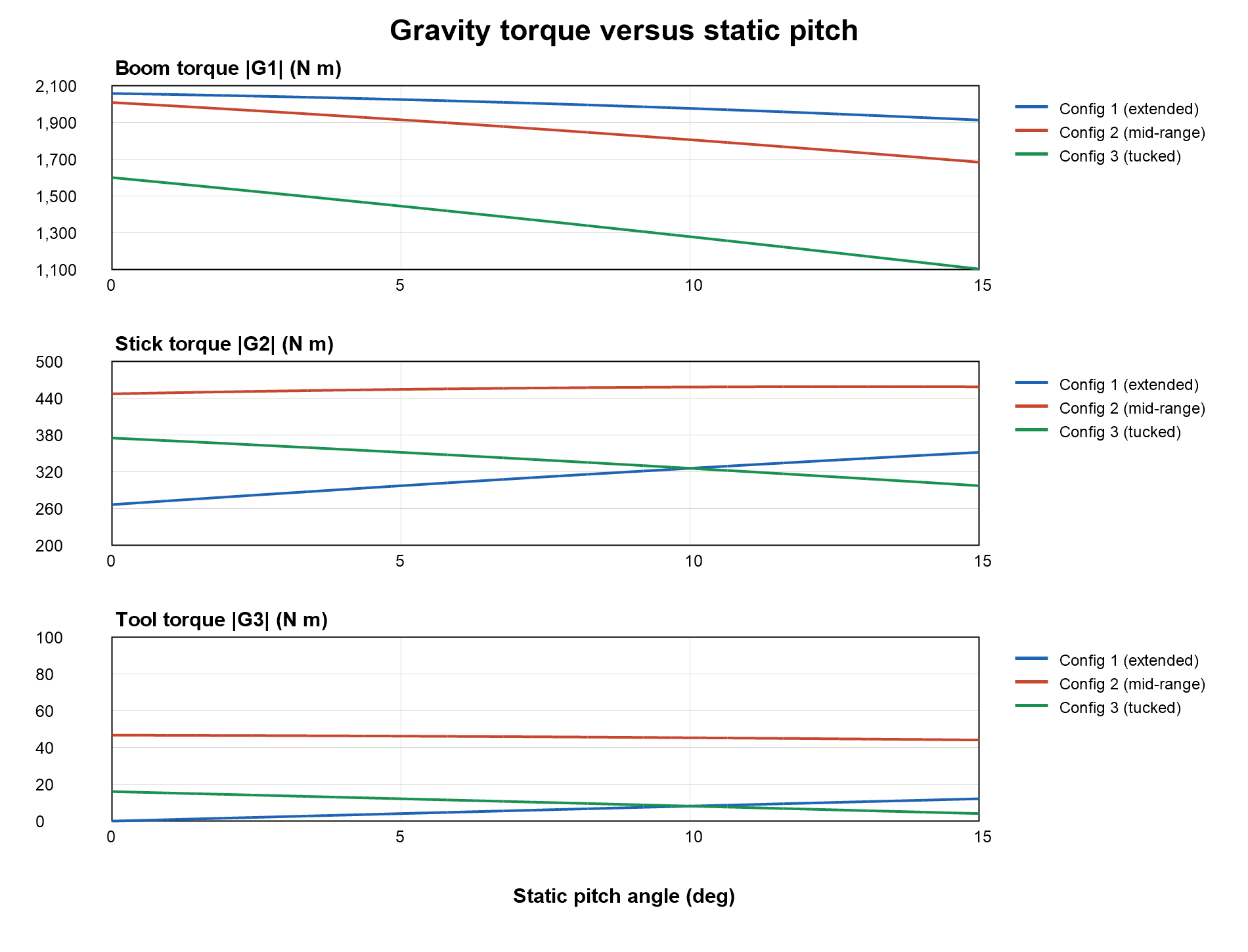
Figure 3. Gravity-torque variation with static pitch for representative arm configurations
Monte Carlo Uncertainty
Table 5 reports the 95th-percentile, bootstrap confidence interval, and maximum uncertainty statistics for the three representative postures. Figure 4 complements the table by showing the end-effector position-error distributions at the same 10° pitch condition. The bootstrap intervals are narrow relative to the separation between the centimeter-level uncertainty and the sub-centimeter ideal computed-torque tracking errors. The qualitative conclusion is therefore insensitive to Monte Carlo sampling noise: residual sensing-point uncertainty is dominated by attitude and parameter priors rather than by the nominal slope-aware tracking controller.
Table 5. Monte Carlo uncertainty summary at 10 deg pitch (N = 1000, seed 42)
Configuration | Torque p95 (%) | Torque p95 CI (%) | Torque max (%) | Tip p95 (cm) | Tip p95 CI (cm) | Tip max (cm) |
Mid-range | 4.32 | 4.06-4.44 | 7.09 | 3.47 | 3.28-3.64 | 5.73 |
Extended | 4.24 | 4.09-4.44 | 7.02 | 2.63 | 2.48-2.76 | 4.34 |
Tucked | 4.44 | 4.24-4.73 | 8.02 | 3.65 | 3.46-3.83 | 6.02 |
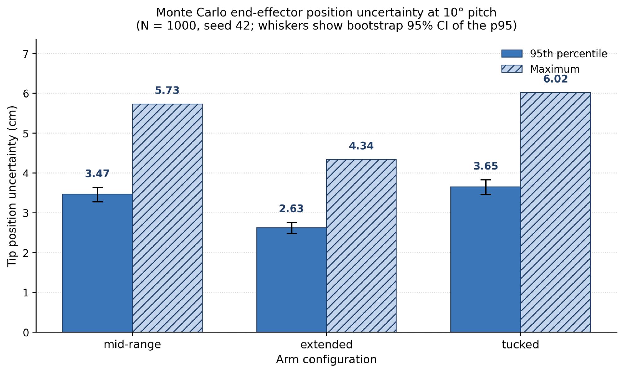
Figure 4. Monte Carlo end-effector position uncertainty at 10° pitch
Computed-Torque Tracking
Table 6 reports the ideal rigid-body tracking errors under nominal and perturbed parameter/attitude scenarios. Figure 5 isolates the gravity-model effect by comparing a flat-ground internal model with a slope-aware internal model on the same 10° pitched plant. These results are rigid-body software results. They should not be read as hydraulic actuator validation. Their role is to show that, once the gravity model is slope-aware, the remaining ideal rigid-body tracking error is much smaller than the sampled parameter/attitude uncertainty.
Table 6. Computed-torque tracking under parameter and attitude perturbations.
Scenario | Joint err max/RMS (deg) | Tip err max/RMS (cm) | Orientation err max/RMS (deg) |
Nominal | 0.0001 / 0.0001 | 0.0004 / 0.0003 | 0.0000 / 0.0000 |
Mass +5 percent | 0.1338 / 0.0627 | 0.1322 / 0.1064 | 0.0792 / 0.0563 |
Mass +5 percent + 2 kg payload error | 0.2660 / 0.1286 | 0.5852 / 0.5484 | 0.3308 / 0.2932 |
Mass +5 percent + 2 kg + IMU pitch error 1 deg | 0.2979 / 0.1475 | 0.6027 / 0.5613 | 0.3458 / 0.3088 |
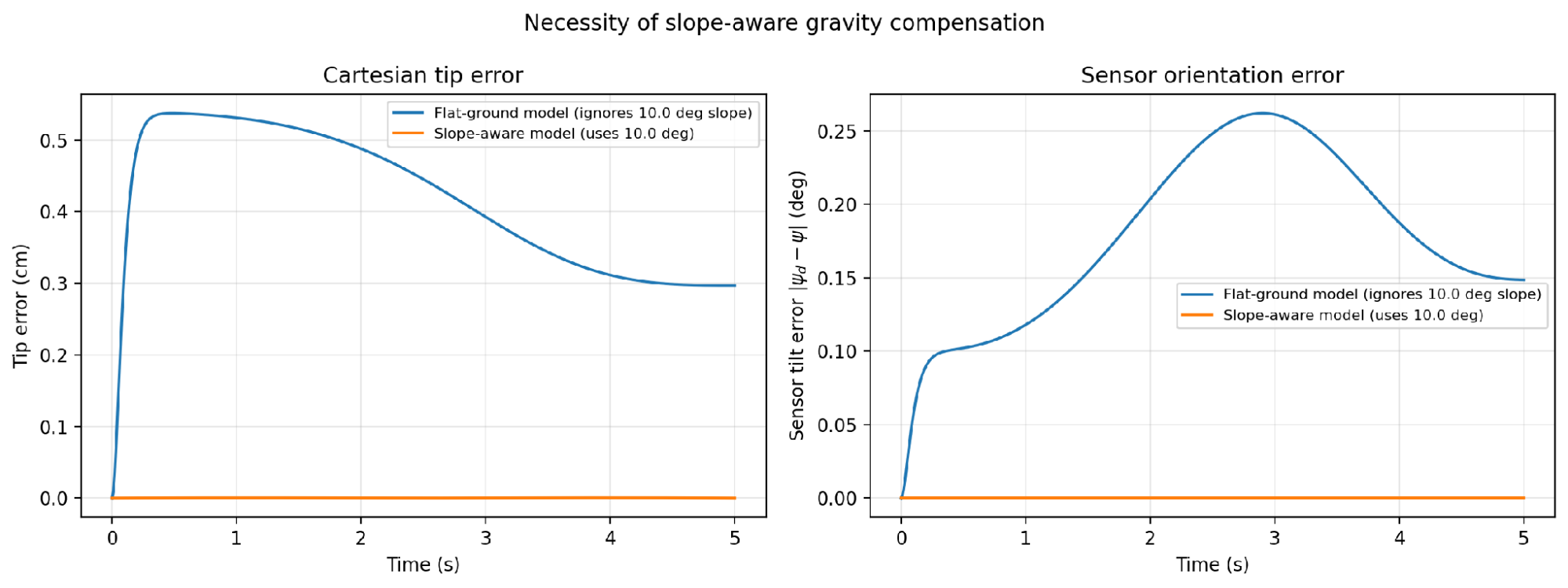
Figure 5. Flat-ground versus slope-aware computed-torque tracking on a 10° slope
Runtime Benchmark
Table 7 reports the timing benchmark used to assess whether the gravity-only update is meaningfully lighter than recomputing the full rigid-body model in the present Python implementation. Because absolute timing depends on the processor, operating system, interpreter, and numerical-library stack, these values are reported only as relative software timing in the reproducibility environment; no embedded controller or real-time operating system was timed.
Table 7. Software runtime benchmark for the current Python implementation
Operation | Mean time per sample | Source |
Gravity-only update | 24.0 microseconds | Python timing in this study |
Full D + h + G recomputation | 38.9 microseconds | Python timing in this study |
Closed-form IK | 4.0 microseconds | Python timing in this study |
Table 7 note. Timings were obtained from the current Python implementation on an Intel Core i5-8400 CPU @ 2.80 GHz with 16 GB RAM, Windows 10 Pro 64-bit, and Python 3.13.11. They indicate relative computational cost only and should not be interpreted as hardware-independent or embedded real-time guarantees. Target-controller deployment requires retiming on the actual processor and software stack. |
Gravity-Torque Sensitivity Trigger
The trigger in Table 4 is derived from the normalized worst-case gravity-torque deviation defined in this section. It is used only as a model-bias indicator for deciding when the flat-ground gravity term becomes noticeably inconsistent with the pitched-chassis model.
The flat-ground gravity bias used in the sensitivity analysis is first defined as
| 
| (7) |
For each joint, the normalized worst-case gravity-torque deviation over the admissible posture grid  is
is
| 
| (8) |
The reported 5.7-6.3° value is the first pitch angle at which  crosses 0.10 for the tested joints. Because
  is based on gravity-torque maxima over the posture grid, it is not a pointwise tracking-error bound and is not derived from a probe-specific clearance budget. It is therefore reported only as a gravity-torque sensitivity trigger, not as a stability margin, clearance threshold, or validated controller-switching boundary. For interpretation, the first-order pitch contribution can be written as
| 
| (9) |
Under the fixed-swing planar reduction, pitch produces an in-plane gravity perturbation, whereas the roll-induced lateral component is absorbed by the locked-swing constraint. This approximation is used only to interpret the numerical trend; all reported gravity torques are computed from the full rotated gravity vector in (1) to (4).
Comparison with Other Studies
Table 8 positions the present baseline against related excavator dynamics, control, planning, and uncertainty literature. The comparison is included to clarify that the paper contributes a static-slope rigid-body and uncertainty reference, not a complete hydraulic or field-deployment controller.
Table 8. Literature positioning and scope contrast
Literature area | What prior work covers | How the present paper differs |
Multibody excavator dynamics [5][6] | Larger excavator front-structure dynamics and full multibody formulations. | Focuses on a compact Bobcat E20-class arm with a sensor payload and static-slope gravity recomputation. |
Parameter identification [8][9] | Inertial/friction parameter identification for excavator arms. | Uses engineering priors and Monte Carlo uncertainty because the present Bobcat E20 payload parameters are not experimentally identified. |
Chassis pose / moving terrain [10],[12] | Pose compensation and road/terrain excitation in mobile machinery; adaptive controllers for sloped traversal in legged systems [57]. | Holds the chassis parked and treats moving-base effects as future work. |
Electro-hydraulic and safety control [17][18],[21] | Actuator-level robust/adaptive/safety control. | Does not model hydraulic valves, pressure dynamics, saturation, or friction. |
Hydraulic MPC, deadtime, and electro-hydraulic pump control [23],[29],[35],[50] | Regenerative-valve MPC, deadtime/regenerative pipelines, pressure-feedback gain-scheduled MPC, and ECU-based pump-control integration. | Uses only a rigid-body computed-torque surrogate to isolate gravity mismatch. |
Reinforcement learning and trajectory planning [19][20],[22],[41][42],[46]-[49] | Learning, optimization, and planning for digging or autonomous excavation. | Provides a deterministic static-slope gravity and uncertainty reference that those methods could later use. |
Passivity/constraint tracking [43],[45] and high-precision tracking [44] | Robust or constrained tracking architectures. | Reports only a baseline rigid-body tracking comparison, not a final controller. |
Implication and Explanation of Findings
Translating the centimetre-level uncertainty to the near-ground sensing application clarifies what these numbers mean operationally. A typical pulse-induction or magnetometric demining payload such as the VMF4 maintains a target air gap between roughly 5 cm and 15 cm above the local ground surface, depending on coil design and depth-of-investigation requirements. The 2.63-3.65 cm 95th-percentile horizontal uncertainty reported here is therefore not negligible relative to that air-gap envelope: at the upper end it represents roughly a quarter of the nominal air gap, large enough to alter the apparent signal amplitude on small or shallow targets. This is not a failure of the slope-aware controller, which itself contributes sub-millimetre tracking error in the nominal rigid-body baseline; rather, it shows that without on-platform mass/CoM identification and tighter chassis-attitude estimation, the residual sensing-point uncertainty is dominated by what enters the model through the priors rather than by what enters through the controller. The results imply that, after slope-aware gravity recomputation, ideal rigid-body tracking error is smaller than the centimetre-level sensing-point uncertainty caused by parameter and attitude priors. The next accuracy bottleneck is therefore chassis-attitude estimation, platform-specific mass/CoM identification, and later hydraulic/friction modeling. The 5.7-6.3 deg trigger is only a scheduling indicator for gravity recomputation, not a clearance, stability, or field-deployment limit.
Strengths and Limitations
A strength of the present baseline is its narrow, auditable claim: it separates the parked-base rigid-body gravity update from hydraulic actuation, friction, soil interaction, and moving-base dynamics. The same narrow scope is also its main limitation. The model does not include moving-base acceleration, track-soil compliance, swing dynamics, gimbal reaction torque, friction, valve dynamics, pressure saturation, or hydraulic deadtime. Recent flexible-joint and hydraulic-actuator controllers with disturbance observers [59] illustrate the next layer of dynamics that must be added once the rigid-body baseline is established. Friction, a nontrivial modeling layer even for general robotic manipulators [30], is set to zero in the present analysis to isolate rigid-body gravity mismatch. The omitted actuator dynamics motivate future hydraulic-aware controllers, including regenerative-valve MPC, pressure-feedback gain-scheduled MPC, and integrated electro-hydraulic pump-control strategies, but they are not part of the present static-slope rigid-body claim.
For a moving base,  and the base position become time-varying, and additional inertial terms from base acceleration, angular velocity, and angular acceleration must be appended. The static-slope gravity term developed here remains useful as a component of that later formulation, but the present results should not be read as validation of moving-base tracking, rollover prevention, slip avoidance, or full terrain-following operation.
- CONCLUSIONS
This paper developed a static-slope rigid-body baseline for a Bobcat E20-class mini-excavator carrying a near-ground UXO sensing payload. The main modeling result is a parked-base lemma: with body-fixed joint coordinates, constant base attitude, and zero base velocity and acceleration, the planar inertia matrix and Coriolis/centrifugal vector retain their level-ground form, while the generalized gravity torque must be recomputed from the rotated gravity vector and the center-of-mass Jacobians.
The numerical study shows why this distinction matters. At 15° pitch, the tested gravity-torque change reaches 322.66 Nm, and the identical joint command at 10° pitch produces a 0.6967 m geometric shift of the sensing reference point. Under Monte Carlo uncertainty at 10° pitch, the 95th-percentile end-effector uncertainty is 2.63-3.65 cm. In the ideal rigid-body computed-torque baseline, a flat-ground gravity model produces 0.54 cm maximum tip error under nominal parameters, while the slope-aware model reduces this to numerical-noise level. The 5.7°-6.3° value is retained only as a gravity-torque sensitivity trigger, not as a clearance, stability, or validated switching threshold.
The result supports slope-aware gravity recomputation as a lightweight modeling and control baseline for static near-ground sensing. It does not validate field-ready UXO clearance, hydraulic actuation, friction compensation, soil interaction, moving-base operation, or gimbal reaction dynamics. Future work proceeds in five clearly delineated stages. The first stage replaces the bounded engineering priors with experimentally identified inertial parameters obtained by static and slow-sweep torque measurements on a Bobcat E20-class platform, following the static-decoupled identification strategy reported in [8][9]. The second stage incorporates hydraulic actuator dynamics, including pressure regulation, valve deadband, and saturation, together with joint friction along the lines of [29],[35],[59], converting the present rigid-body computed-torque surrogate into a hydraulic-aware tracking controller suitable for hardware-in-the-loop testing. The third stage extends the parked-base lemma to a quasi-static traversal regime by allowing the chassis attitude and base position to vary slowly in time, appending the corresponding base-acceleration, angular-velocity, and angular-acceleration terms in the kinetic energy. The fourth stage couples the chassis-attitude estimator and the parameter-identification module so that the priors used in the present uncertainty analysis are tightened in real time. Only after these four stages are passed does the fifth stage, hardware validation on a Bobcat E20-class platform with a VMF4-class payload, become a defensible step rather than a speculative claim.
ABBREVIATIONS
The following abbreviations are used in this manuscript.
UXO | : | Unexploded Ordnance |
VMF4 | : | Vallon VMF4-Class Detector |
CTC | : | Computed-Torque Control |
IMU | : | Inertial Measurement Unit |
CoM | : | Center of Mass |
MPC | : | Model Predictive Control |
SMC | : | Sliding-Mode Control |
APPENDIX
Appendix A. Derivation of the Parked-Base Static-Slope Lemma
This appendix expands the proof of Lemma 1 using the same body-fixed notation as the main text. Let be the center-of-mass position of link in the swing frame, let be the fixed swing-to-body rotation, and let be the constant body-to-world rotation during a parked static sweep. The world-frame embedding is
| 
| (A1) |
Under the parked-base assumptions,  is constant, is constant, is constant,
  ,
,  , and
, and  . Differentiating (A1) therefore gives
| 
| (A2) |
Because  is an orthonormal rotation,
  . The translational kinetic energy is consequently
| 
| (A3) |
which is identical to the level-ground body/swing-frame expression. The same argument applies to rotational kinetic energy: a constant base orientation rotates the coordinate embedding but introduces no additional base angular velocity. Hence the total kinetic energy  and the inertia matrix
  are independent of the constant chassis attitude.
The Coriolis/centrifugal torque vector is obtained from derivatives of the same kinetic-energy metric with respect to and . Therefore also retains the level-ground functional form. If a Coriolis matrix is written, the statement applies to the Christoffel-form matrix associated with this same , or equivalently to the torque vector , because itself is not unique.
The potential energy is different because gravity is expressed in the rotated swing frame:
| 
| (A4) |
Differentiating (A4) with respect to q gives
| 
| (A5) |
Equation (A1) to Equation (A5) show that, for body-fixed generalized coordinates and a parked chassis, only the gravity term must be recomputed from the rotated gravity vector. If or becomes time-varying, additional moving-base inertial terms must be included and Lemma 1 no longer applies without modification.
REFERENCES
- O. M. U. Eraliev, K.-H. Lee, D.-Y. Shin, and C.-H. Lee, "Sensing, perception, decision, planning and action of autonomous excavators," Automation in Construction, vol. 141, p. 104428, 2022, https://doi.org/10.1016/j.autcon.2022.104428.
- D. Jud, S. Kerscher, M. Wermelinger, E. Jelavic, P. Egli, P. Leemann, G. Hottiger, and M. Hutter, "HEAP - The autonomous walking excavator," Automation in Construction, vol. 129, p. 103783, 2021, https://doi.org/10.1016/j.autcon.2021.103783.
- T. Zhang, T. Fu, T. Ni, H. Yue, Y. Wang, and X. Song, "Data-driven excavation trajectory planning for unmanned mining excavator," Automation in Construction, vol. 162, p. 105395, 2024, https://doi.org/10.1016/j.autcon.2024.105395.
- A. Jomartov, A. Tuleshov, A. Kamal, and A. Abduraimov, "Design of a cable-driven parallel robot for landmine detection," SN Applied Sciences, vol. 5, p. 299, 2023, https://doi.org/10.1007/s42452-023-05533-2.
- Y. Cao and Y. Xie, "Dynamic modeling of the front structure of an excavator," Nonlinear Dynamics, vol. 91, no. 1, pp. 233-247, 2018, https://doi.org/10.1007/s11071-017-3865-7.
- R. Mitrev, D. Janošević, and D. Marinković, "Dynamical modelling of hydraulic excavator considered as a multibody system," Tehnički vjesnik - Technical Gazette, vol. 24, Supplement 2, pp. 327-338, 2017, https://doi.org/10.17559/TV-20151215150306.
- H. Ding, Z. Sang, Z. Li, J. Shi, Y. Wang, and D. Meng, "Trajectory planning and control of large robotic excavators based on inclination-displacement mapping," Automation in Construction, vol. 158, p. 105209, 2024, https://doi.org/10.1016/j.autcon.2023.105209.
- S. Tafazoli, P. D. Lawrence, and S. E. Salcudean, "Identification of inertial and friction parameters for excavator arms," IEEE Transactions on Robotics and Automation, vol. 15, no. 5, pp. 966-971, 1999, https://doi.org/10.1109/70.795801.
- Y. H. Zweiri, L. D. Seneviratne, and K. Althoefer, "Parameter estimation for excavator arm using generalized Newton method," IEEE Transactions on Robotics, vol. 20, no. 4, pp. 762-767, 2004, https://doi.org/10.1109/TRO.2004.829476.
- Y. Feng, X. Tian, T. Li, and Y. Jiang, "Measurement of mobile manipulator chassis pose change caused by suspension deformation and end-effector accuracy improvement based on multi-sensor fusion," Robotics and Autonomous Systems, vol. 170, p. 104553, 2023, https://doi.org/10.1016/j.robot.2023.104553.
- H. Q. Dong, N. T. Gam, H. M. Cuong, and L. A. Tuan, "Fractional-order fast terminal back-stepping sliding mode control of autonomous robotic excavators," Journal of the Franklin Institute, vol. 361, no. 6, p. 106686, 2024, https://doi.org/10.1016/j.jfranklin.2024.106686.
- V. D. Le and N. M. Kha, "The dynamics of a wheel loader in motion considering random road surface irregularities," Journal of Science and Technique, vol. 20, no. 1, 2025, https://doi.org/10.56651/lqdtu.jst.v20.n01.898.
- S. Kafashan and J. D. Saphores, “Building Sustainably: Annualized Cost of Ownership, Externalities, and the Electrification of Construction Machinery,” Sustainability, vol. 18, no. 12, p. 6343, 2026, https://doi.org/10.3390/su18126343.
- W. Liu, X. Luo, J. Zhang, D. Niu, J. Deng, W. Sun, and J. Kang, "Review on control systems and control strategies for excavators," Journal of Physics: Conference Series, vol. 2301, no. 1, p. 012023, 2022, https://doi.org/10.1088/1742-6596/2301/1/012023.
- T. Okada, T. Yamamoto, T. Doi, K. Koiwai, and K. Yamashita, "Database-driven model predictive control system for online adaptation of an autonomous excavator to environmental conditions," Control Engineering Practice, vol. 145, p. 105843, 2024, https://doi.org/10.1016/j.conengprac.2024.105843.
- M. Lee, H. Choi, C. Kim, J. Moon, D. Kim, and D. Lee, "Precision motion control of robotized industrial hydraulic excavators via data-driven model inversion," IEEE Robotics and Automation Letters, vol. 7, no. 2, pp. 1912-1919, 2022, https://doi.org/10.1109/LRA.2022.3142389.
- H. Feng, J. Jiang, X. Chang, C. Yin, D. Cao, H. Yu, C. Li, and J. Xie, "Adaptive sliding mode controller based on fuzzy rules for a typical excavator electro-hydraulic position control system," Engineering Applications of Artificial Intelligence, vol. 126, p. 107008, 2023, https://doi.org/10.1016/j.engappai.2023.107008.
- X. Tao, K. Liu, J. Yang, Y. Chen, J. Chen, and H. Zhu, “Sliding mode backstepping control of excavator bucket trajectory synovial in particle swarm optimization algorithm and neural network disturbance observer,” Actuators, vol. 14, no. 1, p. 9, 2025, https://doi.org/10.3390/act14010009.
- P. Egli, D. Gaschen, S. Kerscher, D. Jud, and M. Hutter, "Soil-adaptive excavation using reinforcement learning," IEEE Robotics and Automation Letters, vol. 7, no. 4, pp. 9778-9785, 2022, https://doi.org/10.1109/LRA.2022.3189834.
- P. Egli and M. Hutter, "A general approach for the automation of hydraulic excavator arms using reinforcement learning," IEEE Robotics and Automation Letters, vol. 7, no. 2, pp. 5679-5686, 2022, https://doi.org/10.1109/LRA.2022.3152865.
- W. Huang, Q. Wang, S. Yang, J. Zhang, and B. Xu, "Adaptive sliding mode and safety control for excavators using kinematic control barrier function and sliding mode disturbance observer," Automation in Construction, vol. 172, p. 106046, 2025, https://doi.org/10.1016/j.autcon.2025.106046.
- K. Chen, L. Tao, J. Chen, C. Hua, and Q. Li, "Safe reinforcement learning for tracking control of uncertain hydraulic excavators," Nonlinear Dynamics, vol. 113, pp. 26269-26284, 2025, https://doi.org/10.1007/s11071-025-11500-w.
- Z. Jin, M. Gong, D. Zhao, Y. Zhang, W. Liu, J. Zhu, and B. Su, "MPC motion control of boom descending of unmanned excavator based on regenerative valve," Heliyon, vol. 10, no. 9, p. e29915, 2024, https://doi.org/10.1016/j.heliyon.2024.e29915.
- D. Mambetov, V. Jundibayev, U. Kasymov, A. Danyarova, and D. Murzabekov, “Ensuring quick changeability of the working bodies of technological machines in the construction and maintenance of the landscape, road-building, and agricultural industries,” Mechanics Based Design of Structures and Machines, vol. 52, no. 10, pp. 7692-7704, 2024, https://doi.org/10.1080/15397734.2024.2305783.
- D. G. Atinafu, J. Y. Choi, Y. Choi, J. Nam, and S. Kim, “Eicosane-infused heterostructured nanocarbon hybrid aerogel composite for high-performance thermal transport and energy conversion,” Composites Part B: Engineering, vol. 304, p. 112658, 2025, https://doi.org/10.1016/j.compositesb.2025.112658.
- K. Xu, J. Song, Z. Li, F. Guipeng, Z. Zha, and K. Wu, “Research and application of rock asphalt dry-modified fluid mastic asphalt mixture for reflective crack treatment in asphalt pavements,” Case Studies in Construction Materials, p. e05622, 2025, https://doi.org/10.1016/j.cscm.2025.e05622.
- S. Echeandia and P. M. Wensing, "Numerical methods to compute the Coriolis matrix and Christoffel symbols for rigid-body systems," Journal of Computational and Nonlinear Dynamics, vol. 16, no. 9, p. 091004, 2021, https://doi.org/10.1115/1.4051169.
- J. Paziewski, R. Sieradzki, J. Rapinski, D. Tomaszewski, K. Stepniak, J. Geng, and G. Li, “Integrating low-cost GNSS and MEMS accelerometer for precise dynamic displacement monitoring,” Measurement, vol. 242, p. 115798, 2025, https://doi.org/10.1016/j.measurement.2024.115798.
- Y. Yamamoto, J. Qiu, T. Doi, T. Nanjo, K. Yamashita, and R. Kikuuwe, "A position controller for hydraulic excavators with deadtime and regenerative pipelines," IEEE Transactions on Automation Science and Engineering, vol. 22, pp. 855-871, 2025, https://doi.org/10.1109/TASE.2024.3354952.
- G. Fabris, L. Scalera, P. Boscariol, and A. Gasparetto, “Static and dynamic friction models for robotic manipulators: state of the art and experimental comparison,” Journal of Intelligent & Robotic Systems, vol. 112, article 41, 2026, https://doi.org/10.1007/s10846-026-02390-0.
- X. Zhang, R. Shi, Z. Zhu, and Y. Quan, “Adaptive nonsingular fixed-time sliding mode control for manipulator systems’ trajectory tracking,” Complex & Intelligent Systems, vol. 9, pp. 1605–1616, 2023, https://doi.org/10.1007/s40747-022-00864-w.
- S. Hu, Y. Wan, and X. Liang, “Adaptive fast terminal sliding mode control of robotic manipulators based on joint torque estimation and friction compensation,” International Journal of Robust and Nonlinear Control, vol. 34, no. 18, pp. 12223–12238, 2024, https://doi.org/10.1002/rnc.7624.
- G. R. Petrovic and J. Mattila, "Mathematical modelling and virtual decomposition control of heavy-duty parallel-serial hydraulic manipulators," Mechanism and Machine Theory, vol. 170, p. 104680, 2022, https://doi.org/10.1016/j.mechmachtheory.2021.104680.
- D. Guan, N. Yang, J. Lai, M.-F. F. Siu, X. Jing, and C.-K. Lau, "Kinematic modeling and constraint analysis for robotic excavator operations in piling construction," Automation in Construction, vol. 126, p. 103666, 2021, https://doi.org/10.1016/j.autcon.2021.103666.
- J. T. Jose, J. Das, and S. K. Mishra, "Dynamic improvement of hydraulic excavator using pressure feedback and gain scheduled model predictive control," IEEE Sensors Journal, vol. 21, no. 17, pp. 18526-18534, 2021, https://doi.org/10.1109/JSEN.2021.3083677.
- V. L. Nguyen, C.-H. Kuo, and P.-T. Lin, "Reliability-based analysis and optimization of the gravity balancing performance of spring-articulated serial robots with uncertainties," Journal of Mechanisms and Robotics, vol. 14, no. 3, p. 031016, 2022, https://doi.org/10.1115/1.4053048.
- M. Busch, F. Schnoes, A. Elsharkawy, and M. F. Zaeh, "Methodology for model-based uncertainty quantification of the vibrational properties of machining robots," Robotics and Computer-Integrated Manufacturing, vol. 73, p. 102243, 2022, https://doi.org/10.1016/j.rcim.2021.102243.
- T. Yaren and S. Kizir, "Efficiency assessment of SOA-based computed torque control: A comparative analysis with NE-based approach," Proceedings of the Institution of Mechanical Engineers, Part I: Journal of Systems and Control Engineering, vol. 238, no. 8, pp. 1410-1424, 2024, https://doi.org/10.1177/09596518241238414.
- G. Simonini, M. Baracca, T. V. Cavaliere, A. Bicchi, and P. Salaris, "A novel formulation for adaptive computed torque control enabling low feedback gains in highly dynamical tasks," IEEE Access, vol. 13, pp. 69898-69909, 2025, https://doi.org/10.1109/ACCESS.2025.3561635.
- A. Srour, A. Franchi, P. R. Giordano, and M. Cognetti, “Experimental validation of sensitivity-aware trajectory planning for a redundant robotic manipulator under payload uncertainty,” IEEE Robotics and Automation Letters, vol. 10, no. 2, pp. 1561–1568, 2025, https://doi.org/10.1109/LRA.2024.3519857.
- Z. Yao, S. Zhao, X. Tan, W. Wei, and Y. Wang, "Real-time task-oriented continuous digging trajectory planning for excavator arms," Automation in Construction, vol. 152, p. 104916, 2023, https://doi.org/10.1016/j.autcon.2023.104916.
- Y. Shen, J. Wang, C. Feng, and Q. Wang, "Hybrid-driven autonomous excavator trajectory generation combining empirical driver skills and optimization," Automation in Construction, vol. 165, p. 105523, 2024, https://doi.org/10.1016/j.autcon.2024.105523.
- J. Gong, J. Chen, D. Cai, W. Wei, and Y. Long, "Disturbance observer-based passivity and impedance control for trajectory tracking in autonomous hydraulic excavators," Automation in Construction, vol. 170, p. 105898, 2025, https://doi.org/10.1016/j.autcon.2024.105898.
- H. Feng, Y. Zhong, C. Zhou, S. Ji, C. Yin, and D. Cao, “Collaborative high-precision trajectory control for heavy excavators based on an improved particle swarm optimization algorithm,” Automation in Construction, vol. 180, article 106546, 2025, https://doi.org/10.1016/j.autcon.2025.106546.
- C. Hua, J. Zhou, B. Zhang, Y. Zhang, and J. Zhang, "Low-complexity tracking control of hydraulic excavator systems with asymmetric full-state constraints," Journal of the Franklin Institute, vol. 362, p. 107345, 2025, https://doi.org/10.1016/j.jfranklin.2024.107345.
- T. Fu, Z. Hu, T. Zhang, Q. Bi, and X. Song, "Physics-Informed Neural Networks-Based Online Excavation Trajectory Planning for Unmanned Excavator," Chinese Journal of Mechanical Engineering, vol. 37, p. 131, 2024, https://doi.org/10.1186/s10033-024-01109-2.
- T. Wang, X. He, Y. Zhou, and F. Shao, "Optimization of Unmanned Excavator Operation Trajectory Based on Improved Particle Swarm Optimization," Actuators, vol. 14, no. 5, p. 226, 2025, https://doi.org/10.3390/act14050226.
- P. Egli, L. Terenzi, and M. Hutter, "Reinforcement Learning-Based Bucket Filling for Autonomous Excavation," IEEE Transactions on Field Robotics, vol. 1, pp. 170-191, 2024, https://doi.org/10.1109/TFR.2024.3432508.
- T. Zhang, Z. Zhou, C. Yan, J. Yao, X. Song, and K. Li, "Digital twin-driven excavation trajectory planning of unmanned excavator based on multidisciplinary co-simulation," Automation in Construction, vol. 178, p. 106404, 2025, https://doi.org/10.1016/j.autcon.2025.106404.
- C. Wang, “Integrated electronic control of electro-hydraulic excavators,” Journal of Engineering and Applied Science, vol. 73, article 157, 2026, https://doi.org/10.1186/s44147-026-01023-5.
- X. Wei, S. Fan, Y. Zhang, W. Gao, F. Shen, X. Ming, and J. Yang, “A robust adaptive error state Kalman filter for MEMS IMU attitude estimation under dynamic acceleration,” Measurement, vol. 242, Part D, article 116097, 2025, https://doi.org/10.1016/j.measurement.2024.116097.
- S. B. Farahan, J. J. M. Machado, F. G. de Almeida, and J. M. R. S. Tavares, “9-DOF IMU-based attitude and heading estimation using an extended Kalman filter with bias consideration,” Sensors, vol. 22, no. 9, p. 3416, 2022, https://doi.org/10.3390/s22093416.
- M. Liu, Y. Cai, L. Zhang, and Y. Wang, “Attitude estimation algorithm of portable mobile robot based on complementary filter,” Micromachines, vol. 12, no. 11, p. 1373, 2021, https://doi.org/10.3390/mi12111373.
- H. Kallel and K. Iqbal, “Online estimation of manipulator dynamics for computed torque control of robotic systems,” Sensors, vol. 25, no. 22, p. 6831, 2025, https://doi.org/10.3390/s25226831.
- P. Galarce-Acevedo and M. Torres-Torriti, “Discrete-time computed torque control with PSO-based tuning for energy-efficient mobile manipulator trajectory tracking,” Robotics, vol. 15, no. 1, p. 19, 2026, https://doi.org/10.3390/robotics15010019.
- Z. He, S. Piao, X. Leng, and Y. Wu, “Uneven terrain walking with linear and angular momentum allocation,” Sensors, vol. 23, no. 4, p. 2027, 2023, https://doi.org/10.3390/s23042027.
- P. Li, B. Yin, L. Zhang, and Y. Zhao, “Adaptive control algorithm for quadruped robots in unknown high-slope terrain,” Journal of Engineering Research, vol. 13, no. 3, pp. 1771–1784, 2025, https://doi.org/10.1016/j.jer.2024.05.018.
- R. Kang, H. Ning, F. Meng, and Z. He, “Whole-body synergy-based balance control for quadruped robots with manipulators on sloped terrains,” Cyborg and Bionic Systems, vol. 5, p. 0201, 2024, https://doi.org/10.34133/cbsystems.0201.
- V. D. Phan, C. P. Vo, and K. K. Ahn, “Adaptive neural tracking control for flexible joint robot including hydraulic actuator dynamics with disturbance observer,” International Journal of Robust and Nonlinear Control, vol. 34, no. 13, pp. 8744–8767, 2024, https://doi.org/10.1002/rnc.7412.
- K. Liu, H. Zhong, M. Chen, J. Yang, H. Qiang, and S. Kang, “Analysis of vibration characteristics of hydraulic excavator device under flat ground conditions,” Modelling and Simulation in Engineering, vol. 2024, p. 4390530, 2024, https://doi.org/10.1155/2024/4390530.
- S. Wang, B. Zhang, J. Zhou, B. Yang, and Y. He, “Time-jerk optimal trajectory planning for industrial robots with coupled interpolation function selection,” Journal of Field Robotics, vol. 41, no. 4, pp. 917–941, 2024, https://doi.org/10.1002/rob.22298.
- F. Lozer, L. Scalera, P. Boscariol, and A. Gasparetto, “Planning optimal minimum-jerk trajectories for redundant robots,” Robotics and Autonomous Systems, vol. 192, p. 105049, 2025, https://doi.org/10.1016/j.robot.2025.105049.
Pham Chi Thanh (Static-Slope Dynamics and Uncertainty of a Compact-Excavator Manipulator for Near-Ground Sensing)