ISSN: 2685-9572 Buletin Ilmiah Sarjana Teknik Elektro
Vol. 8, No. 3, June 2026, pp. 837-854
An Enhanced 3DOF PID Control Scheme for Boost Converters with Improved Transient and Steady-State Performance
Abrar Abdul Hameed Rasheed 1, Marwan Kanaan Ismael 2, Ali Sachit Kaittan 3
1 Department of Electromechanical Techniques, Baquba Technical College, Middle Technical University, Baghdad, Iraq
2 Department of Renewable Energy Techniques, Baquba Technical Institute, Middle Technical University, Baghdad, Iraq
3 Department of Power and Electrical Machines Engineering, University of Diyala, Diyala Governorate, Iraq
ARTICLE INFORMATION |
| ABSTRACT |
Article History: Received 25 March 2026 Revised 21 May 2026 Accepted 19 June 2026 |
| 
This article discusses a novel Three-Degree-of-Freedom (3DOF) PID control design for DC-DC boost converters aimed at improving transient and steady-state performance. Boost converters are essential in power electronic devices but present challenges due to their nonlinear characteristics and right-half-plane zero issues that hinder traditional control methods. Basic PID controllers often exhibit faults like overshoot and poor disturbance rejection. The proposed 3DOF PID controller addresses these issues by incorporating set-point weighting and separating feedforward from feedback control, allowing for independent tuning of reference tracking and disturbance rejection. A systematic design approach is employed to optimize controller parameters for various operating conditions. The controller was implemented in a MATLAB/Simulink environment and tested against a detailed boost converter model. Simulation results show that the 3DOF PID controller significantly reduces rise time from 0.45 s to 0.18 s, settling time from 0.8 s to 0.3 s, and overshoot to under 2% compared to standard PID controllers, which typically show 10-12% overshoot. Additionally, under load disturbance, the voltage dip is reduced from 3 V to 1.2 V, with recovery time improved from 0.5 s to 0.2 s. Overall, the findings confirm that the 3DOF PID controller enhances transient response, disturbance rejection, and stability, making it a promising solution for high-performance power electronic applications. The acquired data confirm that the suggested 3DOF PID controller improves the boost converter's transient and steady state performance while preserving its stability in dynamic situations. |
Keywords: DC–DC Boost Converter, 3DOF PID Control, Set-Point Weighting, Feedforward Compensation, Small-Signal Modeling |
Corresponding Author: Abrar Abdul Hameed Rasheed, Department of Electromechanical Techniques, Baquba Technical College, Middle Technical University, Baghdad, Iraq. abrar.abdulhameed@mtu.edu.iq |
This work is open access under a Creative Commons Attribution-Share Alike 4.0 
|
Document Citation: A. A. H. Rasheed, M. K. Ismael, and A S. Kaittan, “An Enhanced 3DOF PID Control Scheme for Boost Converters with Improved Transient and Steady-State Performance,” Buletin Ilmiah Sarjana Teknik Elektro, vol. 8, no. 3, pp. 837-854, 2026, DOI: 10.12928/biste.v8i3.16253. |
INTRODUCTION
DC-DC boost converters find thorough application in current power electronics schemes by way of their capability to increase the input voltage to a greater amount of voltage, accompanied by extreme efficiency and miniaturization. They are very main in energy from non-depleting source systems, energetic vehicles, assault administration systems, fuel containers, and convenient electronic devices. Although widely used, the control of boost converters to deliver high performance is not easy because they are non-linear, time-varying, and non-minimum-phase devices by nature [1][2]. Practically, nevertheless, boost converters are prone to any of the doubts, such as load differences, recommended voltage differences, parasitic components, and changing nonlinearities. Such determinants can drastically lower bureaucracy performance, resulting in weak transient reaction, bigger overshoot, stable-state mistakes, and even instability in likely operating environments. The development of strong and productive control strategies is so detrimental to be intelligent to placate the transient and stable-state conduct needs. (PID) Controllers are one of the ultimate low control systems secondhand related to manufacturing and in academic research because of their candor, ready-to-use exercise, and performance private undeviating systems [3]. Traditional PID control, in turn, is commonly inadequate to boost converters due to its lack of sufficient ability to deal with the nonlinear dynamics and the right-half-plane (RHP) zero of boost converters.
This is a drawback that leads to slow transient response and reduced stability margins when working under a variation of conditions [4]. To address these issues, various state-of-the-art control procedures have been submitted in the drama, such as sliding mode control (SMC), model predictive control (MPC), fuzzy logic control (FLC), adjusting control, and strong nonlinear control systems [5][6]. These suggestions support better acting, but can frequently result in more computational complexity, trouble of exercise, and sympathy to limit producing into unity. Hence, there is a need to enhance simple PID control buildings in accordance with the break between purity and extreme-accomplishment qualifications that is evenly increasing [7]. One of these hopeful guidelines is the advancement of fractional-order PID (FOPID) controllers that use the idea of partial mass in the gallbladder in the control society to determine the boss accompanying more harmony, in addition to better dynamic reaction [8]. However, the proficient exercise of the FOPID operators can confirm expected monotonicity and may require closeness methods, which increases the requirement of utilization. The addition is gaining organizing and adaptive PID controllers, by which boss parameters are altered in real time for action or event to suit the variations in bureaucracy.
These methods may be effective but concede the possibility touch lack stability and strength, except that designed to accompany care [9]. The notion of 2-degree-of-freedom (2DOF) PID control has recently attracted some consideration due to its freedom to independently determine the setpoint-tracking and disturbance-rejection properties of a system. Weighting factors introduced in the proportional and derivative paths of 2DOF PID controllers offer a greater flexibility than the conventional single-degree-of-freedom structure [10]. Nonetheless, even 2DOF PID controllers might not be able to meet the demanding performance specifications of boost converters that have to work under strongly dynamic conditions. To increase control performance, a (3DOF) PID control structure has been suggested. The 3DOF PID boss establishes the classic PID structure but increases more bringing into harmony parameters to allow the liberated control of reference following, upset rejection, and crash debilitation possessions. This additional adaptability confesses more proper modeling of order change, crucial to better interim explanations and minor steady-state mistakes [11]. The use of 3DOF PID control, specifically in the context of boost converters, is of particular interest on account of its appeal as an orderly method of achieving a robust middle ground among two points: swift reaction, small omission, and commotion fortitude. With an appropriate choice of the controller parameters, the negative effects of the RHP zero and nonlinearities can be reduced without making the control structure complex and difficult to implement. The design and tuning of 3DOF PID controllers to boost converters is not thoroughly studied yet, even though it could have significant benefits. Literature tends to look at linearized systems and does not comprehensively address the effects of nonlinearities within the system, variation in parameters, and actual system operating conditions. Also, orderly tuning methods are necessary to guarantee the best efficiency without inevitably utilizing trial and error or heuristics.
The problem statement states that despite the extensive development of boost converter control strategies, the nonlinear and non-minimum-phase nature of boost converters makes it difficult to achieve fast transient responses, low overshoots, good disturbance rejection, and stable operation all at once. Advanced nonlinear and optimization-based PID controllers typically increase implementation complexity and calculation, but classic PID controllers may have performance constraints with rapid load and modifications to the input. Therefore, a control strategy that may improve both transient and steady state performance while maintaining real-time practicality and convenience of implementation is needed. A PID controller for a DC–DC boost converter with (3DOF) is presented in this study to address these issues and enhance the three areas of disturbance rejection, reference tracking, and system robustness.
The section is a review of the most applicable literature, with emphasis on classical PID-based techniques, nonlinear techniques of control, and recent advancements in multi-degree-of-freedom PID-based control structures. The initial study of the control of a boost converter was mostly based on linear control methods developed based on the small-signal model. An averaged linear model about a particular operating point models the nonlinear switching characteristics of the converter in this framework. Based on this model, classical (PI) and (PID) controllers were designed to regulate the output voltage [12][13]. Although such controllers are cheap and commonly used in industry, they usually perform poorly when the converter is driven by large signal variations or by changing loads.
Specifically, a right-half-plane (RHP) zero of the control-to-output transfer function puts an essential constraint on the bandwidth and transient response that can be achieved. Some improvements and changes have been suggested to overcome the drawbacks of the traditional PID control. A typical method is gain scheduling, in which PID parameters change with operating conditions, like input voltage or load current [14]. Even though gain scheduling embellishes performance at a more extensive operating point, it makes it necessary proper scheme and can present complexity to honest-period implementation. Online adaptation of the limits of the boss by the employment of belief algorithms or adjusting laws has been further investigated in adjusting PID control [15]. Nevertheless, union questions and sensitivity to the explosion in calculations can be a question accompanying specific procedures. Robust control techniques are the subject of another line of inquiry. proposed for managing doubts and disturbances. (SMC) has happened of great interest by way of allure inborn robustness and active vital reaction [16]. SMC-located controllers of boost converters are fit capably responding to limit alternatives and external disturbances, but have a blathering restriction that grants permission to cause bigger switching deficits and electromagnetic impedance. A difference of processes has existed to accept free these troubles, holding bound-layer processes and best-order flowing fashions, though at the fee of larger arrangement complicatedness. Another complex technique that has been efficiently used to improve converters is the MPC [17]. MPC includes an individual-period model of authority to predict conduct and best control conduct over an established horizon.
The policy determines great vital acting and restraint management. Nevertheless, it is ordinarily limited in practice to one excellent computational request and the necessity of precise arrangement models. (FLC) and affected (ANN) are more creative control methods that have been surveyed for employment in a boost preacher. FLC is not tied to a distinguishing numerical model and can handle nonlinearities well, utilizing wandering rules [18]. Equally, ANN-located controllers have the capability to determine complex order dynamics utilizing a dossier and offer adjusting control aids [19]. Although they have their benefits, these plans occasionally need a lot of bringing into harmony or preparation, and occasionally lack transparency in their design, that maybe a loss in terms of safety-detracting uses. In the current age, the PID (FOPID) controllers have taken a hopeful next step beyond the classical PID control. The use of partial-order integral and descendants gives FOPID controllers more qualities of exemption to harmony and can offer better performance in conditions of strength and active reaction [20]. Several studies have confirmed that FOPID controllers are direct in the use of DC-DC converters. However, they are consistently implemented utilizing estimated orders, which grant permission to cause better computational and hardware complexity. (2DOF) PID control has been projected to improve the adaptability of chaste PID controllers. Separate tuning parameters are employed in a 2DOF structure to track a setpoint and reject disturbances, giving independent control over these responses [21].
This method has been accustomed to embellishing converters accompanying meaningful gains in omit decline and disturbance denial. Nonetheless, adjusting the tuning procedure can still be difficult, and the performance improvements might not be adequate in highly nonlinear or very varying circumstances. Expanding upon the 2DOF model, (3DOF) PID controllers have recently been considered. The 3DOF arrangement adjoins an extra limit that offers extra decoupling between citation following, commotion elimination, and disturbance attenuation. This increases the flexibility, and thus it is possible to control the system dynamics more accurately, and the overall performance is also improved. Despite promising results of 3DOF PID controllers in process control and other fields, limited usage is observed in power electronic converters, especially boost converters. Recently, everything has reliable to combine 3DOF PID control with growth approaches like genetic algorithms (GA), particle swarm optimization (PSO), and ant colony optimization (ACO) to acquire optimal limits bringing into harmony [22]. Such techniques can go a great distance in improving boss performance through industrialization of the bringing into harmony mechanism and blocking local minima. But they can be computationally exhaustive and are not always appropriate in real-time for action or an event. Also, composite control methods that include the unification of PID control and different methods have been submitted. As an example, PID-SMC mixture controllers inquire to integrate the strength of accelerating manner control with the unity of PID controllers [23]. Likewise, PID controllers with feedforward compensation or disturbance observers have been invented to improve performance [24]. Although these orders supply a bettering, they usually create a greater construction complexity and, in a few cases, ability need extra sensors or system news.
Since they feature a single control structure for both reference tracking and disturbance rejection functions, typical PID controllers are sometimes referred to as one-degree-of-freedom (1DOF) controllers. Although 2DOF PID controllers offer flexibility by separating disturbance rejection management from set-point tracking using weighting functions, their performance is limited in highly nonlinear and frequently changing operating circumstances. Therefore, the focus of this study is on a 3DOF PID structure with an extra degree of freedom added for separate control of transient forming, disturbance rejection, and reference tracking. This study's primary goal is to demonstrate the advantages of the suggested 3DOF PID controller over the industry's most popular PID controller, the 1DOF PID, by contrasting it with the traditional 1DOF PID controller. In light of the existing research, the drawbacks of 2DOF PID models are examined. Comparison Table 1 between them.
Table 1. Comparison between
Controller | Tracking | Disturbance Rejection |
| Complexity |
1DOF PID | Moderate | Weak |
| Low |
2DOF PID | Better | Moderate |
| Medium |
Proposed 3DOF PID | Excellent | Strong |
| Medium |
Research Gap and Contribution of the Proposed Method
The comparative examination between the available methods of controlling boost converters shows that there is a significant discrepancy between the ease and the performance capacity. Classical PID controllers are further top-selling on account of their simplicity to implement, but have harsh losses, containing extreme overshoot, slow transient backlash, feeble upset removal, and an adjustment between velocity and faultlessness. Although gain-scheduled and adaptive PID controllers seek to enhance performance, they add complexity and cannot be as robust to rapid system changes. Extended control techniques, including (SMC), (MPC), (FLC), and NN control, are more dynamic and robust. The methods are, however, more prone to using complex mathematical models, extensive computational resources, or a lot of tuning, which makes them less applicable in real-time and cost-sensitive applications. In the same way, the non-integer operators of (FOPID) controllers are hard to implement, yet provide greater flexibility. By decoupling set-point tracking and disturbance rejection, the introduction of (2DOF) PID controllers partially resolves these problems. However, they are not very flexible and cannot enhance handling under dynamic and nonlinear operating situations of boost converters. In comparison, the suggested 3DOF PID controller is successful in closing this gap by adding to the traditional PID arrangement other tuning parameters, namely set-point weighting factors and a feedforward feedback arrangement. It enables the independent control of tracking performance and disturbance rejection without a huge complexity increase in the system. As a consequence, the submitted approach has a fast transient answer, lower omission, better constant-state accuracy, and is stronger to changeful operating environments.
This article suggests a novel 3DOF PID control blueprint for boost converters that aims to achieve greater transient and stable-state conduct compared to common control orders. The projected approach leverages the supplementary qualities of independence in the controller form to help key performance verification, containing rise opportunity, calming time, omit, and stable-state error. Furthermore, the boss design contains strength concerns to guarantee a fixed shift under variable load and recommendation atmospheres.
The main contributions of this work can be encapsulated as follows:
- A novel formulation of a 3DOF PID controller tailored specifically for boost converter applications, addressing the challenges posed by nonlinear dynamics and RHP zero behavior.
- A well-behaved tuning means that speeds autonomous adaptation of following, upset refusal, and crash nervousness characteristics.
- Comprehensive investigation of the projected control scheme in conditions of cohesion, strength, and performance verification.
- 4-Validation of the proposed approach through simulation results, demonstrating significant improvements over conventional PID and 2DOF PID controllers.
METHODS
Modeling of the Boost Converter
A usual DCDC boost converter is a photoelectric revolution in capacity computers that boosts a smaller recommendation service to a larger controlled manufacturing generated power. The elementary study of land consists of four main parts: a pushbutton, an inductor, a diode, and a gain capacitor [25][26]. The revolution is fed by a strength beginning (the recommendation) that is convinced into gain strength apiece monthly exchange of the semiconductor switch. Inductors are very important in the strength deposition and transfer. When the switch acts, the current through the inductor begins to flow through the inductor, where the strength is stored in the magnetic field of the inductor's currents. In this period of time, the diode is reverse-partial, and the manufacturing stage is not recommended [27]. With the stop from operating, the strength in the inductor is self-inducted by way of the diode upon the product capacitor and load to present an amount generated power degree, the recommended energized matter. The diode offers the unidirectional flow of current, which does not admit the reverse flow of current to the input. The production capacitor is a ploy that uses exchanging ripple to smooth the production strength and balance the yield potential across the load to a somewhat continual profit [28][29]. The changing repetitiveness and the burden phase of the control signal used to switch decide the movement of the boost preacher. The boost converter operates in two distinct modes depending on the state of the switch:
Mode 1: Switch ON, when the switch is excited, the inductor is connected directly across the recommendation beginning [30]. The current through the inductor rises in an undeviating fashion, and energy is stored in the magnetic field of the inductor. At this ending, the diode is reverse-partial, and the crop capacitor determines the strength to the load.
Mode 2: Switch OFF, the inductor current cannot change shortly when the switch is switched. The inductor capacity changes opposition, biasing the diode in the forward direction, and allowing current to travel through the inductor to the load. The strength amplified in the inductor is disregarded in relation to the production capacitor and load, so pushing the crop potential above the recommended energized matter [31].
Mathematical Modeling
The design of an effective control strategy is shown in Figure 1, it is necessary to have a mathematical model of the boost converter. The switching and the presence of energy-storage elements mean that the boost converter is a nonlinear device. Thus, the system dynamics is often expressed in terms of state-space modeling [32][33].
The key state variables chosen for the boost converter are:
- Inductor current,

- Output capacitor voltage,

The duty cycle,  , is the portion of time that the switch is ON in a switching period. The converter is analyzed in two switching states to derive the mathematical model.
Case 1: Switch ON (Duty interval dT), when the switch is ON, the diode is reverse-biased, and the inductor is directly connected to the input source [34].
The voltage across the inductor is equal to the input voltage:
| 
| (1) |
Using the inductor voltage–current relationship:
| 
| (2) |
The output capacitor supplies current to the load:
| 
| (3) |
Case 2: Switch OFF (Interval (1 − d)T), when the switch is OFF, the inductor releases its stored energy to the output.
The voltage across the inductor is:
| 
| (4) |
The inductor current dynamics become:
| 
| (5) |
The capacitor current equation is:
| 
| (6) |
State - Space Averaged Model
By averaging the equations over one switching period, the state-space model of the boost converter is obtained [35]. The state equations are:
| 

| (7) |
Where, is the inductor current, is the output voltage,  is the input voltage, L is the inductance, C is the output capacitance, R is the load resistance, and d is the duty cycle. These equations represent the nonlinear averaged model of the boost converter.
Each variable is divided into a steady-state factor and a tiny displacement component to develop the linearized small-signal model:
Where, is the inductor current, is the output voltage, is the duty cycle.
When the adjusted variables are added to the nonlinear averaged equations and higher-order displacement terms are ignored [36], the outcome is:
| 

| ()9 |
The control-to-output transfer function that results may then be written as follows:
| 
| (10) |
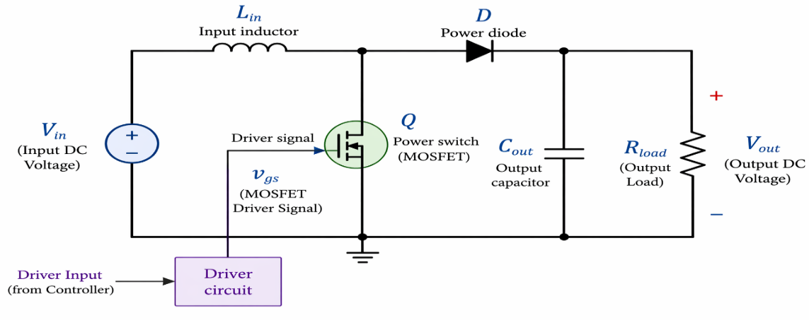
Figure 1. Displays the control strategy
The small-signal linearized model of the boost converter around the nominal operating point served as the foundation for the suggested PID controller architecture for the 3DOF boost converter. The linearization was carried out using an input voltage of 12 V, an output voltage of 24 V, a nominal load resistance of 6 Ω, and a duty cycle of around 0.5. For the purpose of creating and researching the converter stability, a linear averaged model was utilized to approximate the converter dynamics around this operating situation. Although the boost converter is nonlinear and non-minimum-phase, the linearized model was accepted and is commonly utilized in power electronic applications for practical controller design utilizing a PID-based technique to build the control system. It is expected that the boost converter utilized in this study is operating in Continuous Conduction Mode (CCM), which prevents the inductor current from zeroing out during the switching cycle. This operating mode was selected due to its extensive use in circuits for medium- and high-power boost converters, as well as its appropriateness for linear controller design and small-signal averaged modeling. The practical operating condition is satisfied by the duty cycle d:0 < d < 1. The normal operating point in this work is expected to be at a duty cycle of around d=0.5. In the selected operating range, the converter dynamics under CCM operation are well represented by the averaged state space model and transfer function.
Conventional PID Control
One of the most common control strategies in industrial and engineering practice is the PID controller, because of its simple structure, ease of implementation, and satisfactory performance for a large variety of linear systems. PID controllers are established in DC-DC boost converters to control the energized matter brought to the converter by changing the switching phase of the changing signal [37-38]. An established PID boss bases everything on the wrong signal, that is, a distinction between the citation voltage and the real crop service. The boss produces a control indication on account of the blend of three actions: equivalent, necessary, and derivative.
- The proportional (P) term causes an output proportional to the current error, and this gives a rapid response.
- The I (integral) term will add the error to the time, removing steady-state error.
- The derivative (D) term makes predictions of the future trend of the error, which enhances system stability and minimizes overshoot.
Mathematical Representation of PID Controller
Figure 2 demonstrates that the control law of a standard PID controller in the time domain is given by:
| 
| (8) |
Where,  : Control indication (duty cycle in boost converter),
  : Error indication =
  ,
,  : Proportional gain,
  : Integral gain,
  : Derivative gain
In the Laplace domain, the PID controller can be expressed as:
| 
| (9) |
This transfer function highlights how the controller reacts to different frequency components of the error signal.
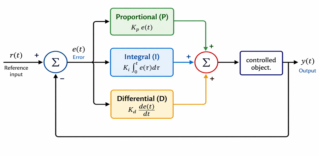
Figure 2. Demonstrates a conventional PID
Proposed 3DOF PID Controller
The 3DOF-PID boss is an advanced expansion of the usual PID building that adds a new quality of ability to move in the composition of the dynamic answer of bureaucracy [39][40]. The 3DOF-PID construction enables the remark following, disturbance denial, and blast debilitation to be brought into harmony alone, unlike the usual PID controller that uses a single wrong signal. Figure 3, an exemplification of a 3DOF-PID boss.
A Mathematical Formulation
General 3DOF Structure: Present the general control law expression in the Laplace domain:
| 
| (10) |
Where,  is the control output (duty cycle);
  is the orientation (target voltage);
  is the measured output voltage;
  is an estimated disturbance (if applicable). Derivation of the Third Degree
  : This is the core novelty. You must define what this specific third degree is doing in your design.
Controller Block Diagram and Implementation
Figure 3, detailed Block Diagram: This is an itemized block drawing illustrating how the habit, the remark, response, and the new tertiary term are used to form the definitive charge era command. This hopeful clearly in accordance with what is depicted.
| 
| (11) |
Set-Point Weighting (Degree 2): Define the set-point transfer function:
| 
| (12) |
Where  and
and  are set-point weights for P and D terms.
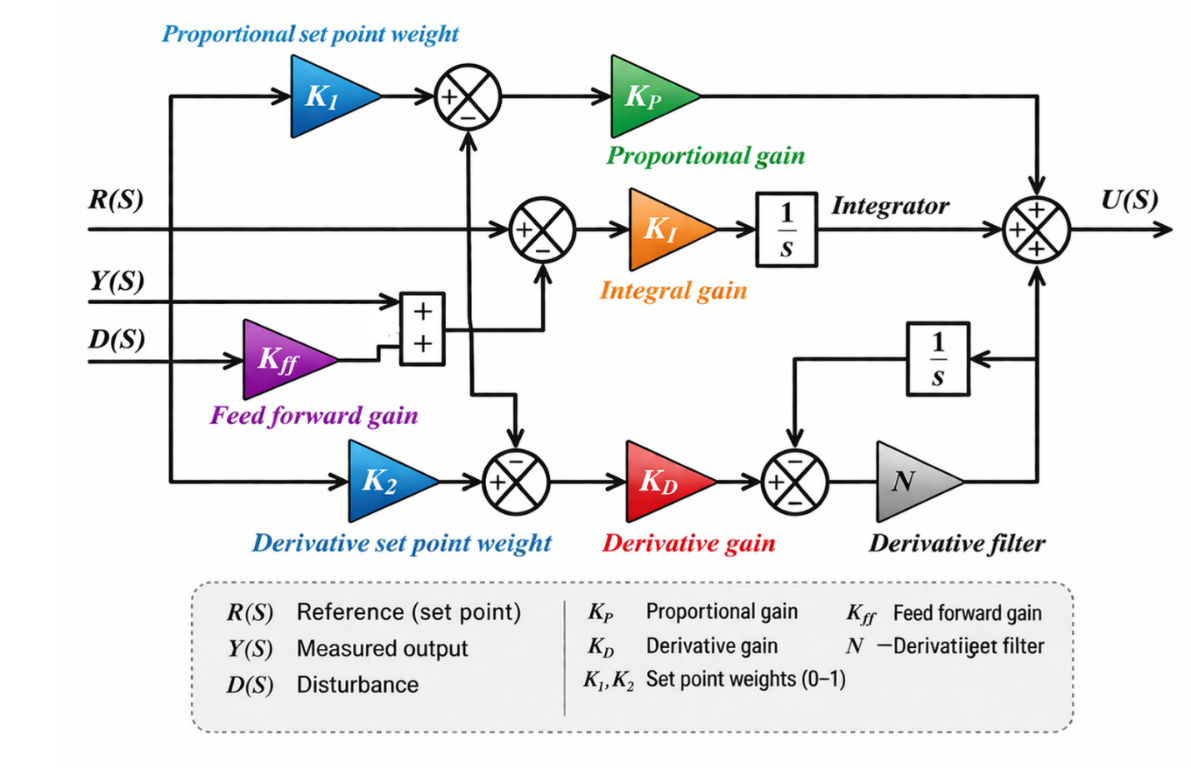
Figure 3. Demonstrates a proposed 3DOF PID Controller
The (PID) and 3DOF-PID control block figure, accompanying a distinguishing shape planned to the shape of the boost preacher whole, is painfully graphical inside the boundaries of Figure 4. This figure is unique and is an essential aid expected to accompany eyes, and materializes the difficult companionships and functionalities that typify the movement of the boost cleric, which is essential in variable requests needing activated matter step-up change. In testing this illustration, the crowd can acquire valuable understandings into the control strategies lethargy, by improving the information on how certain blueprints are effectively reserved and trained in standard.
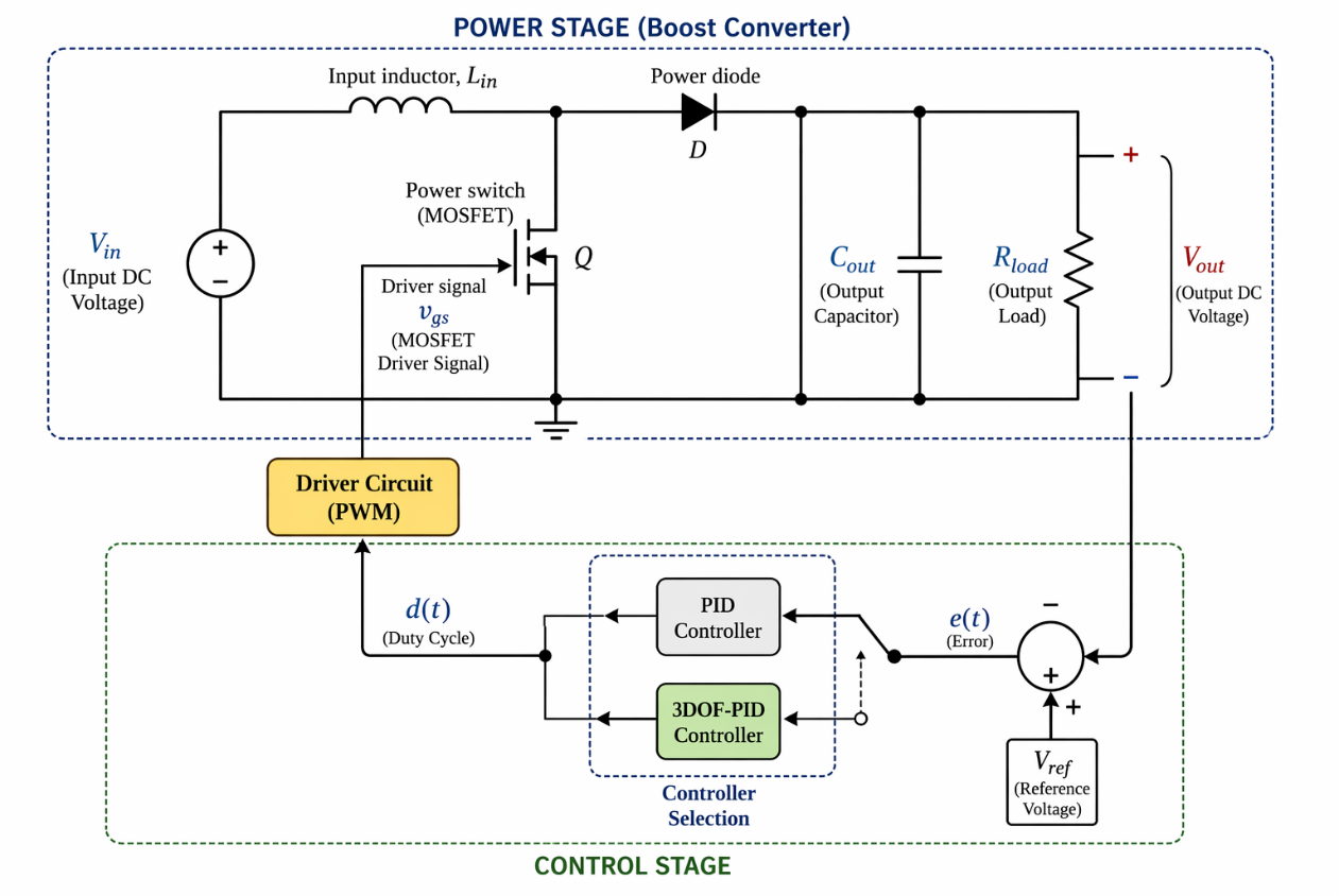
Figure 4. The block illustration of PID and 3DOF-PID
Figure 5 illustrates the general research approach utilized in this work for the creation and assessment of the suggested 3DOF PID controller for the DC–DC boost converter. The (CCM) modeling of the converter is nonlinear, and the process begins with the converter specification. The small-signal transfer function for the controller design is then obtained by deriving and linearizing the averaged state-space equations about the nominal operating point. Next, a structured iterative tuning approach is used to build and fine-tune both the traditional PID controller and the suggested 3DOF PID controller in accordance with the transient and steady state performance requirements.
For real-time implementation, the calculation of the extra weighting and feedforward terms related to the suggested 3DOF PID controller is still comparatively low. In terms of processing needs, the additional computations are negligible and mostly consist of straightforward algebraic computations involving the feedforward compensation path and set-point weighting factors. As opposed to sophisticated controllers like nonlinear control and optimization-based controllers like (MPC), (FLC), or neural-network-based techniques, the suggested controller does not require iterative enhancement, matrix operations, or extensive online computations. Because of this, the calculation is not overly complex and may be implemented on inexpensive digital control platforms such as an FPGA-based implementation, DSP, or microcontroller. The controller is used in real-world applications at switching frequencies that are common for DC–DC boost converters, such as the 50 kHz switching frequency used in this study. Additionally, the simulation results demonstrate fast convergence and steady functioning without creating undue processing delays. Therefore, the suggested 3DOF PID controller is appropriate for real-time power electronic applications as it provides a good compromise between the intended enhanced control performance and implementation simplicity. Table 2 compares the computational complexity and viability of real-time implementation of several DC–DC boost converter control techniques.
Table 2. Computational Complexity Comparison
Controller | Computational Complexity | Real-Time Feasibility |
Conventional PID | Low | Excellent |
2DOF PID | Low–Moderate | Excellent |
Proposed 3DOF PID | Moderate | Very Good |
MPC | High | Limited |
ANN/FLC | High | Moderate |
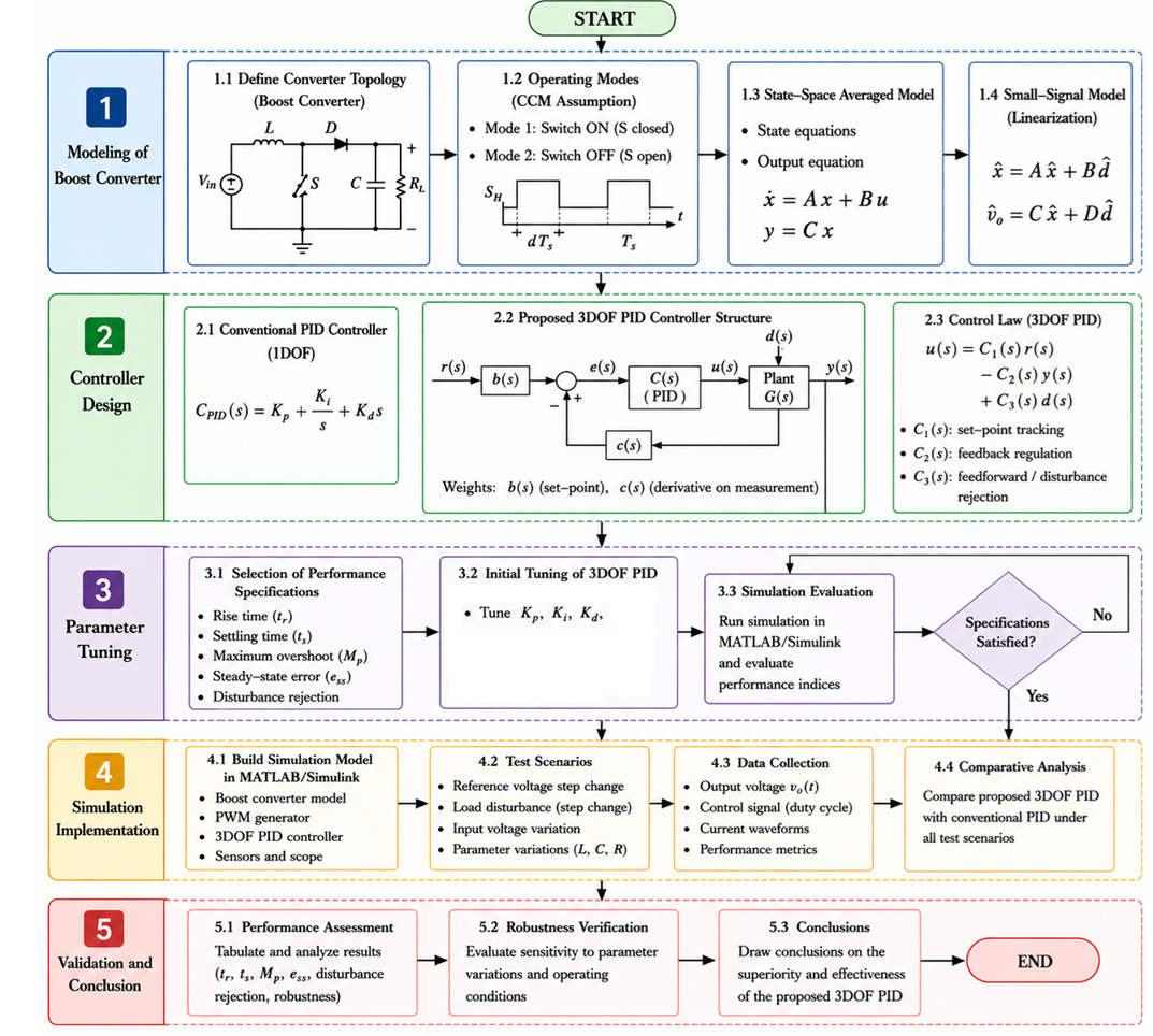
Figure 5. flowchart of the proposed 3DOF PID-controlled boost converter system
RESULT AND DISCUSSION
The projected control procedure is surveyed due to the life of Simulink, which is a direct form to model, simulate, and solve strength capacity makeups. The demeanor of the exchanging, control dynamics, and nonlinearities of bureaucracy is presented in the correct manner by executing the boost preacher and the 3DOF PID controller by way of Simulink blocks. The simulation model consists of: DC input voltage source, Boost converter power stage (inductor, switch, diode, capacitor, and load), PWM generator to implement duty cycle, Controller block (Conventional PID / Proposed 3DOF PID), and Feedback loop to regulate the output voltage. Typical scheme limits in Table 3 and Table 4 are accustomed to evaluating the performance of the boost converter. These parameters are selected in such a way that they maintain a continuous conduction mode (CCM) operation and give a realistic test environment to test controller performance.
Figure 6 demonstrates the response of the output voltage, which makes it clear that the suggested 3DOF PID controller outperforms the conventional PID in dynamic performance when it comes to step changes between 0 and 12 V and 24 V. In the initial step (1 s), the 3DOF PID controller has a much faster rise time of about 0.18 s compared to the conventional PID controller that has a rise time of about 045s. The settling time is further decreased by almost 0.8 s in the PID scenario to approximately 0.3 s in the 3DOF PID scenario. The same occurs at the second step (2s) with the 3DOF controller reaching 24 V faster and with reduced variation than the PID. The two controllers obtain negligible steady-state error (about 0.002 V) in steady-state, but the transient oscillations are significantly reduced in the 3DOF scenario. Generally, the findings validate that the suggested controller offers quicker tracking, lowering overshoot, and enhancing stability throughout the operating range. Overall, the results confirm that the proposed controller provides faster tracking, reduced overshoot, and improved stability across the entire operating range.
Table 3. Factors of the boost converter
Parameter | Symbol | Value | Unit |
Input Voltage | Vin | 12 | V |
Output Voltage (Reference) | Vout | 24 | V |
Inductor | L | 2.2 | mH |
Output Capacitor | C | 470 | µF |
Load Resistance | R | 6 | Ω |
Switching Frequency | fs | 50 | kHz |
Duty Cycle (Nominal) | D | 0.5 | — |
Output Current | IL | 4 | A |
Table 4. Factors of the control
Parameter | symbol | Values |
Proportional Gain |
| 0.8 |
Integral Gain |
| 50 |
Derivative Gain | 
| 0.001 |
Set-point Weight |
| 0.7 |
Set-point Weight |
| 0.3 |
Feedforward Gain | 
| 1 |
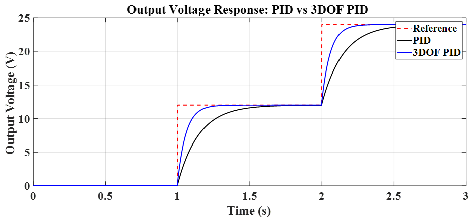
Figure 6. Demonstrates the reaction of the output voltage
Figure 7 displays the response of the output current, which also validates the enhanced functionality of the proposed 3DOF PID controller when operating around the step changes of 0 to 2 to 4 A based on the voltage changes (0, 12, and 24 V) with a load of 6 ohms. The 3DOF PID stabilizes at the reference current of 2 A at the first step (1 s) with a rapid rise time of about 0.15-0.18 s, compared to the conventional PID, which takes about 0.4-0.5 s. Settling time is shortened to approximately 0.25- 0.3 s by the 3DOF PID compared to the PID of almost 0.7- 0.8 s. The same pattern is noticed at the second step (2 s) at which the current reaches 4 A, and the 3DOF PID exhibits faster tracking with a few oscillations, whereas the PID demonstrates slower convergence and a small ripple before stabilization. Both controllers have a steady-state error of nearly zero (0 A) in steady-state, but the 3DOF PID has a far smoother response with lower transient oscillations. For the most part, these judgments signify that the suggested boss leads to a taller active reaction rate, greater following accuracy, and security in current requirements.
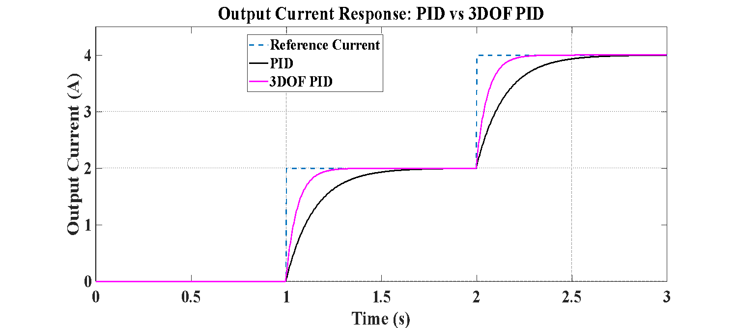
Figure 7. Displays the reaction of the output current
Figure 8 illustrates the reaction of the output power to the step alteration with reference to 0 to 24 to 96 W based on the voltage levels (0,12, and 24 V) when using a load of 6 Ω, illustrating the performance of the proposed 3DOF PID controller. Under the initial condition (1 s), the 3DOF PID attains the reference power of 24 W with a rapid rise time of about 0.18 s, compared to the traditional PID that takes about 0.45 s. Settling time is decreased to approximately 0.3 s (3DOF PID) instead of almost 0.8 s (PID). The PID controller also displays a minor overshoot of about 8-10% (maximum of around 26-27 W), whereas the 3DOF PID restricts it to less than 2% (maximum of around 24.5 W). In the second step (2 s), with the power reaching 96 W, the 3DOF PID will again exhibit quicker convergence and smoother behavior, reaching steady-state after approximately 0.3 s, compared to about 0.7- 0.8 s with the PID controller. The PID response exhibits apparent short-term deviation and slower recovery, whereas the 3DOF PID exhibits reduced oscillations. Both controllers in steady-state attain the desired power with a low steady-state error (about 0 W). In dynamic reaction, the suggested boss is evidently superior as a whole, with three facets: the dynamic reaction, the omission, and cohesion in the complete operating range.
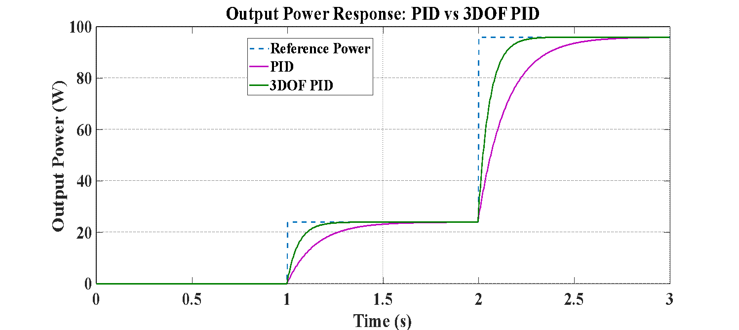
Figure 8. Displays the reaction of the output power
Figure 9 expresses the reaction of the output voltage to the disturbance at the reference of 24 V under load, which is a clear indication of the robustness of the proposed 3DOF PID controller over the conventional PID. Both controllers start with a set point of 24 V, with the 3DOF PID rising at a faster rate of about 0.18 s, and the PID at about 0.45 s, with settling times of about 0.3 s and 0.8 s, respectively. The PID controller at the instant of disturbance (t = 1.5 s) records a large voltage drop of approximately 3 V, which decreases to approximately 21 V, but the 3DOF PID has a much smaller voltage drop of approximately 1.2 V, and the recovery time is approximately 0.2-0.25 s, as compared to the conventional PID recovery time of approximately 0.5 s. Both controllers stabilize to the steady-state output of 24 V, and the steady-state error is negligible (nearly 0 V), but the PID response has a stronger transient response and slower settling. These judgments guarantee that the grown 3DOF PID supervisor is a strong competitor, which helps upset elimination, reduces capacity deviation, and enhances the balance of the system.
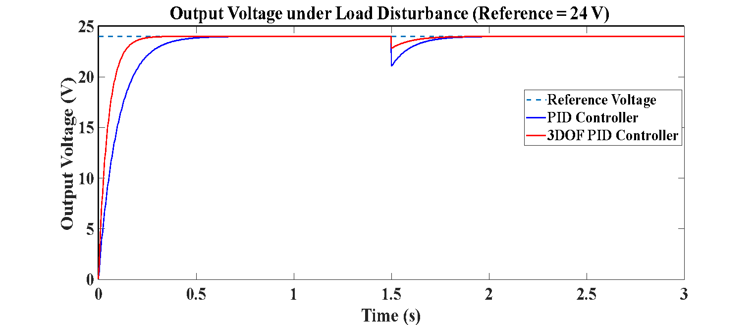
Figure 9. Demonstrates the reaction of the output voltage
Figure 10 displays the current reaction to a load disturbance with a fixed reference voltage of 24 V (a load change of 6 to 3), showing that the proposed 3DOF PID controller has better dynamic performance. First, both the controllers adjust the current to 4 A, with the 3DOF PID having a faster rise time of 0.15-0.18 s, as compared to 0.40-0.45 s with the conventional PID, and settling times respectively of 0.25-0.3 s and 0.70-0.8 s. When the disturbance (t = 1.5 s) is introduced, the reference current goes up to 8 A because of the reduction in the load. The 3DOF PID traces this change quickly with 8 A attained in approximately 0.2-0.25 s, compared to the 0.5 s of the PID controller. Further, the PID response shows a small overshoot of about 5-8% (peaking at about 8.3-8.5 A) with apparent oscillations, compared to the 3DOF PID that constrains the overshoot to less than 2% (≈ 8.1 A) with a much smoother response. Both controllers reach the desired current, with a very small steady-state error (< 0 A) in steady state, but the proposed controller will track much faster, reduce oscillations, and have better stability when sudden changes in load occur.
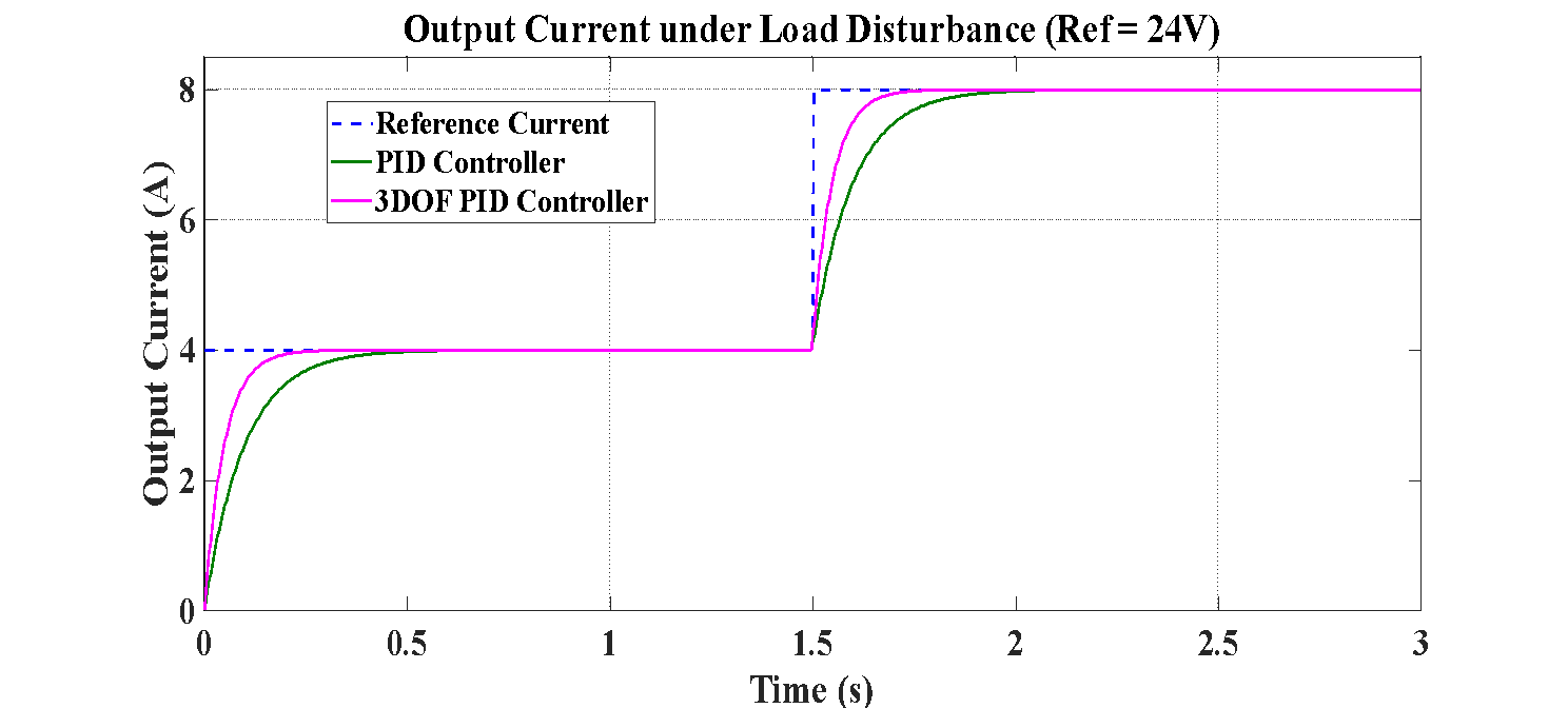
Figure 10. Demonstrates the current response
Figure 11 illustrations the effectiveness of proposed 3DOF PID controller can be seen in the output power reaction to load disturbance at a constant reference voltage of 24 V. First, the output power of 96 W with a load of 6 Ω and 3DOF PID settles to this value in under 0.18 s (a fast rise time) as opposed to 0.45 s with the conventional PID, and both settling times are about 0.3 and 0.8 s, respectively. When disturbance occurs (t = 1.5 s), the load reduces to 3 Ω, and the reference power rises to 192 W. The 3DOF PID responds to this change quickly, reaching 192 W in just 0.25-0.3 s, compared to the 0.5-0.6 s of the PID manager. The transient deviation of the PID response has been shown to have an overshoot of about 8-10% (≈200-210 W) and significant oscillations, whereas the 3DOF PID response has a smaller overshoot of less than 2% (≈194-196 W) and a much smoother transition. Both controllers reach the desired power in steady-state with a tiny steady-state error (2 W), but the proposed 3DOF PID converges faster, has lower transient error, and is more stable when there is a sudden modification in load.
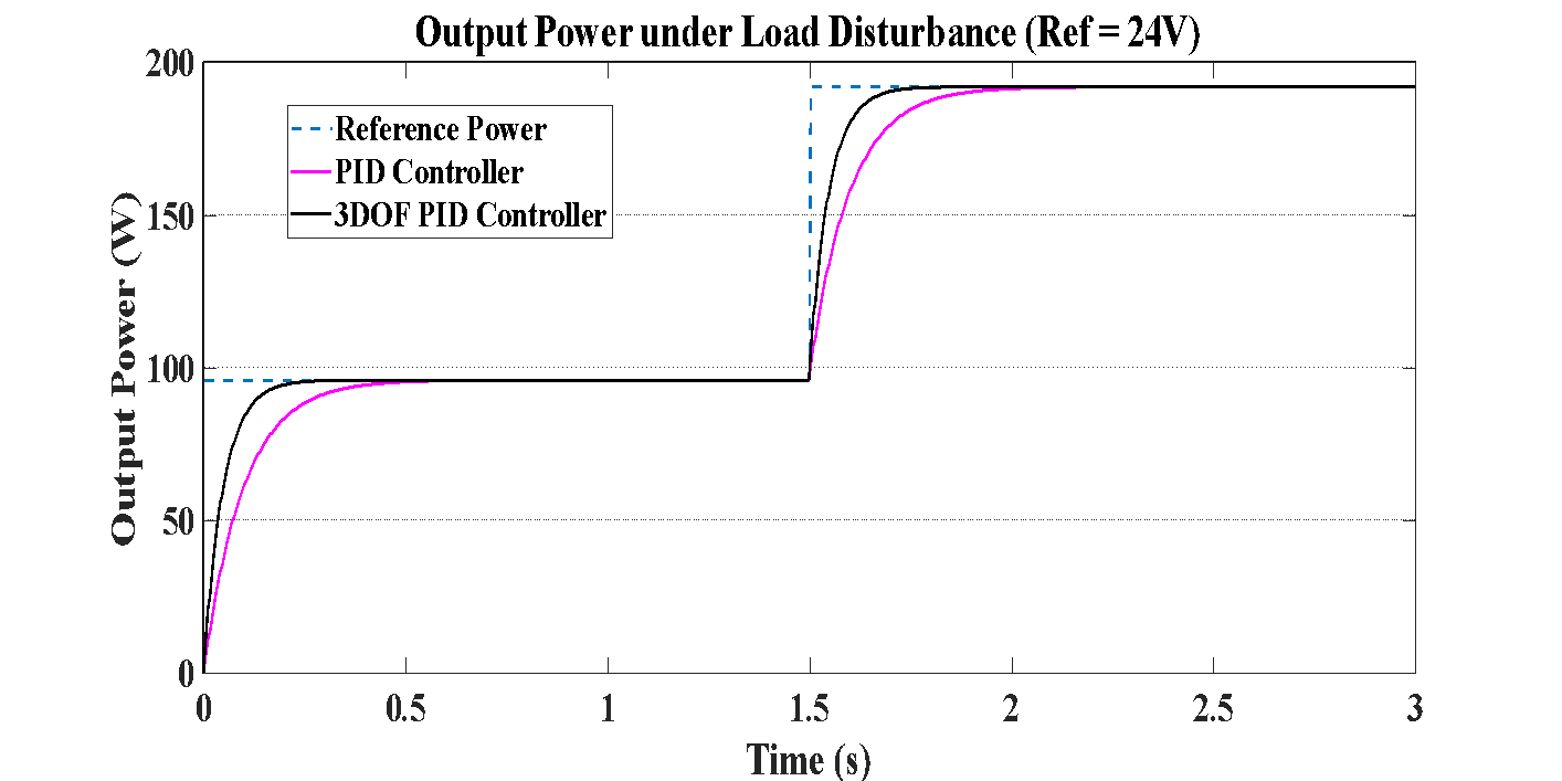
Figure 11. Demonstrates the reaction of the output power
Figure 12 presents that the switching frequency response is an indication of the enhanced stability of the suggested 3DOF PID controller relative to the traditional PID around the nominal frequency of 50 kHz. At the start of the transient (t ≈0-0.5 s), the PID controller is highly oscillating, with the maximum value of around 54 kHz (+4 kHz deviation) and the minimum of around 47.5 kHz ( -2.5 kHz deviation). Conversely, the 3DOF PID exhibits much lower oscillations, 51.2 maximum (+1.2) and 49.5 minimum ( -0.5). Over time, as the steady-state (t ≈ 1s) is approached, the controllers both stabilize around the nominal 50 kHz, although the PID has a few residual oscillations, and the 3DOF PID approaches stabilizing more gradually. When disturbance (t = 1.5 s) occurs, the PID controller reveals a conspicuous spike of up to approximately 52 kHz (+2 kHz) and then slowly decays, requiring approximately 0.5 s to reach a steady level. In the meantime, the 3DOF PID has a significantly smaller deviation, reaching a maximum of about 50.8 kHz (+0.8 kHz), and stabilizing to steady-state within some 0.2-0.25 s. During steady-state (t > 2 s), the two controllers stabilize at the nominal frequency of 50 kHz, but the 3DOF PID reaches this with small oscillations. These findings indicate that the suggested controller is effective in minimizing the frequency deviations from approximately 3.5-4 kHz (PID) to approximately 1 kHz (3DOF PID), resulting in enhanced switching stability and decreased switching stress.
The suggested controller's steady state error was then quantitatively examined for a range of line and load fluctuations, as shown in Table 5. When operating circumstances varied, such as line variation with an error of around 0.42 V and load disturbance with an error of roughly 0.31 V, the steady-state error of the traditional PID controller was found to be substantial. The outcome demonstrates that the suggested 3DOF PID controller effectively lowered the SSE to 0.05 V and 0.03 V for the two scenarios, respectively. These benefits were also observed in the management of power and current, where the suggested controller resulted in much reduced steady state variations. The outcomes demonstrate the robustness and tracking efficacy of the suggested method.
The results of the imitation are presented in Table 6, which distinctly indicate that the projected 3DOF PID boss is superior to the normal PID boss in all experimental positions. The 3DOF PID has a quicker rise time, shorter settling time, and much less overshoot in physical ability, current, and capacity reactions. It is well healthy under load commotion with a tinier strength drop, less current fluctuation and capacity change, and quicker improvement rate. The exchanging repetitiveness reasoning more indicates that the 3DOF PID is running familiar with the theoretical repetitiveness of 50 kHz, and oscillations are considerably tinier than accompanying the standard PID. Even though the 3DOF PID increases a little portion of calculation necessity, the conduct, establishment, and efficiency increase is very clear, and it is very value utilizing it in boost preacher uses.
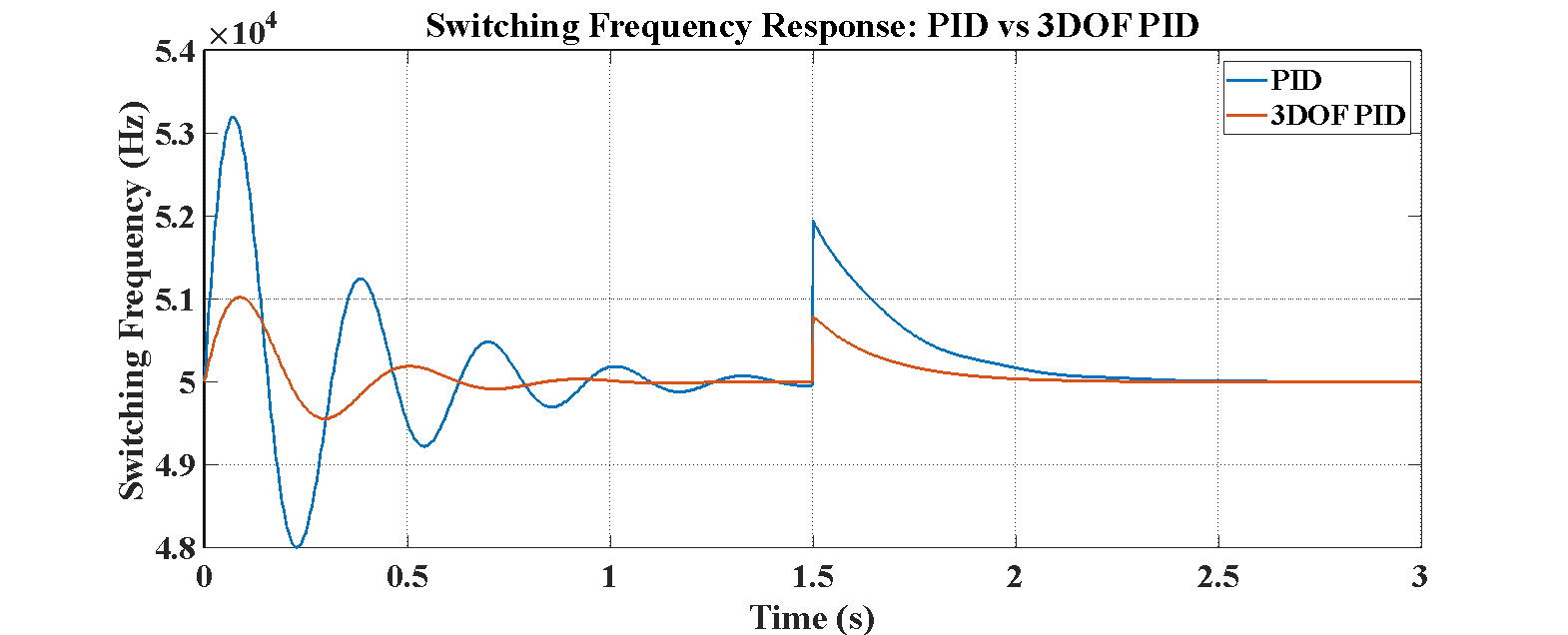
Figure 12. Demonstrates the switching frequency response
Table 5. Steady-State Error Comparison under Line and Load Variations
Operating Condition | Reference | PID | 3DOF PID |
Line variation (12 → 24 V) | 24 V | 0.42 V | 0.05 V |
Load disturbance (6 Ω → 3 Ω) | 24 V | 0.31 V | 0.03 V |
Current regulation | 8 A | 0.12 A | 0.01 A |
Power regulation | 192 W | 2.8 W | 0.4 W |
Table 6. Performance Comparison between PID and 3DOF PID
Performance Metric | PID Controller | 3DOF PID Controller |
Rise Time (Voltage) | 0.45 s | 0.18 s |
Settling Time (Voltage) | 0.8 s | 0.3 s |
Overshoot (Voltage) | 10–12% | < 2% |
Rise Time (Current) | 0.4–0.5 s | 0.15–0.18 s |
Settling Time (Current) | 0.7–0.8 s | 0.25–0.3 s |
Overshoot (Current) | 8–10% | < 2% |
Rise Time (Power) | 0.45 s | 0.18 s |
Settling Time (Power) | 0.8 s | 0.3 s |
Overshoot (Power) | 8–10% | < 2% |
Voltage Dip (Disturbance) | 3 V | 1.2 V |
Recovery Time (Voltage) | 0.5 s | 0.2–0.25 s |
Current Overshoot (Disturbance) | 5–8% | < 2% |
Power Overshoot (Disturbance) | 8–10% | < 2% |
Switching Frequency Deviation | ±3.5–4 kHz | ±1 kHz |
Frequency Recovery Time | ~0.5 s | ~0.2 s |
CONCLUSIONS
In order to improve the transient responsiveness, insensitivity to disturbances, and steady-state performance under various operating modes, this research presented a novel 3DOF PID controller for DC–DC boost converter applications. The controller was designed using the small-signal linear model of the boost converter in (CCM) and evaluated under reference voltage changes, load disturbances, and parameter adjustments using MATLAB/Simulink simulations. According to the testing results, the boost converter using the suggested 3DOF PID controller performed better than the traditional PID controller. The settling time was reduced from 0.8 s to almost 0.3 s (approximately 62.5% reduction), while the rising time was reduced from around 0.45 s to 0.18 s (about 60% reduction). Additionally, the overshoot was reduced from 10–12% to less than 2%, indicating improved tracking accuracy and transient stability. Additionally, the suggested controller had reduced steady state error, improved noise and disturbance rejection, and improved duty cycle regulation in dynamic working environments. Furthermore, when mild changes were made to the inductance and capacitance settings, the controller demonstrated good performance stability without affecting the stability of the closed-loop response. In order to prevent the controller bandwidth from expanding into the effective (RHP) zero frequency area, the closed-loop response research and the stability analysis by the tiny signal transfer function characteristics helped to maintain stable converter operation. In comparison to the traditional PID controller, the suggested controller also has some additional computational complexity. However, because of the weighting and feed-forward elements, the additional computations are primarily straightforward algebraic calculations. The validation in this study is restricted to simulation-based methods employing MATLAB/Simulink only. Future research will concentrate on experimental validation using hardware prototypes and hardware-in-the-loop (HWIL) digital control platforms such as FPGA devices and DSP. Additional testing at (DCM), with significant input-voltage fluctuations, and with renewable energy systems such as photovoltaic and fuel-cell applications, will also be considered. In conclusion, the suggested 3DOF PID controller is appropriate for the control scheme of contemporary power electronic converter applications and provides an efficient trade-off between dynamic performance increase, disturbance suppression capability, implementation convenience, and robustness.
DECLARATION
Acknowledgement
The researchers sincerely appreciate their respective colleges for their assistance, which made this investigation possible.
Conflicts of Interest
There is no conflict of interest disclosed by the researchers.
REFERENCES
- R. S. Inomoto, J. R. B. d. A. Monteiro and A. J. S. Filho, "Boost Converter Control of PV System Using Sliding Mode Control With Integrative Sliding Surface," in IEEE Journal of Emerging and Selected Topics in Power Electronics, vol. 10, no. 5, pp. 5522-5530, 2022, https://doi.org/10.1109/JESTPE.2022.3158247.
- N. A. Ahmed, B. N. Alajmi, I. Abdelsalam, and M. I. Marei, "Soft Switching Multiphase Interleaved Boost Converter With High Voltage Gain for EV Applications," in IEEE Access, vol. 10, pp. 27698-27716, 2022, https://doi.org/10.1109/ACCESS.2022.3157050.
- K. A. Singh, A. Prajapati, and K. Chaudhary, "High-Gain Compact Interleaved Boost Converter With Reduced Voltage Stress for PV Application," in IEEE Journal of Emerging and Selected Topics in Power Electronics, vol. 10, no. 4, pp. 4763-4770, 2022, https://doi.org/10.1109/JESTPE.2021.3120802.
- Marwan Kanaan Ismael, Saif Talal Bahar, and Ahmed Aizaldeen Abdullah, “Harmonic Elimination Method for Permanent Magnet Synchronous Motor Utilizing Active Disturbance Rejection Control,” Proc. eng. technol. Innov., vol. 30, pp. 11–23, 2025, https://doi.org/10.46604/peti.2024.14386.
- S. T. Bahar, W. Wang, and H. Qiu, “AI-Enhanced Model Predictive and Active Disturbance Rejection Control for High-Performance Permanent Magnet Synchronous Motor Drives,” Energies, vol. 19, no. 11, p. 2574, 2026, https://doi.org/10.3390/en19112574.
- M. Veerachary and P. Kumar, "Analysis and Design of Quasi-Z-Source Equivalent DC-DC Boost Converters," in IEEE Transactions on Industry Applications, vol. 56, no. 6, pp. 6642-6656, 2020, https://doi.org/10.1109/TIA.2020.3021372.
- A. A. Abdullah, A. Aldhahab, and H. M. Al Abboodi, “Detection and Classification of Eye Diseases using Hybrid Deep Features with Decision Tree Algorithm,” 3rd International Conference on Advances in Engineering Sciences and Technology (AEST), pp. 1–6, 2024, https://doi.org/10.1109/AEST63017.2024.10960200.
- S. Pirpoor, S. Rahimpour, M. Andi, N. Kanagaraj, S. Pirouzi, and A. H. Mohammed, "A Novel and High-Gain Switched-Capacitor and Switched-Inductor-Based DC/DC Boost Converter With Low Input Current Ripple and Mitigated Voltage Stresses," in IEEE Access, vol. 10, pp. 32782-32802, 2022, https://doi.org/10.1109/ACCESS.2022.3161576.
- P. Mohseni, S. Mohammadsalehian, M. R. Islam, K. M. Muttaqi, D. Sutanto, and P. Alavi, "Ultrahigh Voltage Gain DC–DC Boost Converter With ZVS Switching Realization and Coupled Inductor Extendable Voltage Multiplier Cell Techniques," in IEEE Transactions on Industrial Electronics, vol. 69, no. 1, pp. 323-335, 2022, https://doi.org/10.1109/TIE.2021.3050385.
- G. Li, X. Jin, X. Chen, and X. Mu, "A novel quadratic boost converter with low inductor currents," in CPSS Transactions on Power Electronics and Applications, vol. 5, no. 1, pp. 1-10, 2020, https://doi.org/10.24295/CPSSTPEA.2020.00001.
- A. A. Abdullah, A. Aldhahab, and H. M. Al Abboodi, “Eye disease classification based on hybrid deep features with principal component analysis and blending ensemble learning,” International Journal of Intelligent Engineering and Systems, vol. 18, no. 6, 2025, https://doi.org/10.22266/ijies2025.0731.12.
- S. T. Bahar and H. Qiu, “Amelioration of Traditional PI Boost Converter Utilizing Linear Active Disturbance Rejection Controller - Mode Predictive Control Strategy,” International Journal of Robotics and Control Systems, vol. 6, no. 1, pp. 305–323, 2026, https://doi.org/10.31763/ijrcs.v6i1.2364.
- M. Dasohari, N. Vishwanathan, S. Porpandiselvi, and A. R. M. Vani, "A Soft-Switched Boost Converter Based LED Driver With Reduced Input Current Ripple," in IEEE Access, vol. 12, pp. 45904-45922, 2024, https://doi.org/10.1109/ACCESS.2024.3377122.
- M. Veerachary and M. R. Khuntia, "Design and Analysis of Two-Switch-Based Enhanced Gain Buck-Boost Converters," in IEEE Transactions on Industrial Electronics, vol. 69, no. 4, pp. 3577-3587, 2022, https://doi.org/10.1109/TIE.2021.3071696.
- C. -Y. Chan, S. Chincholkar and W. Jiang, "A Modified Fixed Current-Mode Controller for Improved Performance in Quadratic Boost Converters," in IEEE Transactions on Circuits and Systems II: Express Briefs, vol. 67, no. 10, pp. 2014-2018, 2020, https://doi.org/10.1109/TCSII.2019.2942057.
- L. K. Dangeti, G. Chilakalapudi, and A. Kumar, "An improved Hybrid switched inductor and switched capacitor based DC-DC Converter to reduce the voltage stress across the switch," 2023 IEEE Silchar Subsection Conference (SILCON), pp. 1-5, 2023, https://doi.org/10.1109/SILCON59133.2023.10404832.
- F. A. Villarroel et al., "Stable Shortest Horizon FCS-MPC Output Voltage Control in Non-Minimum Phase Boost-Type Converters Based on Input-State Linearization," in IEEE Transactions on Energy Conversion, vol. 36, no. 2, pp. 1378-1391, June 2021, https://doi.org/10.1109/TEC.2021.3055733.
- G. L. Deshmukh and C. B. Kadu, "Design of a two-degree-of-freedom PID controller for a temperature control system," 2016 International Conference on Automatic Control and Dynamic Optimization Techniques (ICACDOT), pp. 586-589, 2016, https://doi.org/10.1109/ICACDOT.2016.7877653.
- M. Almaged, S. I. Khather, and A. I. Abdulla, “Design of a discrete PID controller based on identification data for a SimScape buck boost converter model,” International Journal of Power Electronics and Drive System (IJPEDS), vol. 10, no. 4, pp. 1797 1805, 2019, https://doi.org/10.11591/ijpeds.v10.i4.pp1797-1805.
- S. Pareek, M. Kishnani, and R. Gupta, “Optimal tuning of PID controller using Meta heuristic algorithms,” 2014 International Conference on Advances in Engineering & Technology Research (ICAETR -2014), pp. 1-5, 2014, https://doi.org/10.1109/ICAETR.2014.7012816.
- Saif Talal Bahar and Raed A. Abd-Alhmeed, “Reduce-Complexity of Predictive Current Control for a 3-Phase Voltage Source Inverter,” JT, vol. 7, no. 3, pp. 16–25, Sep. 2025, https://doi.org/10.51173/jt.v7i3.2621.
- R. La’biran and M. Kristiawan, “Optimization of Association Rule Using Ant Colony Optimization (ACO) Approach,” Wasit Journal of Computer and Mathematics Science, vol. 2, no. 3, pp. 100-107, 2023, https://doi.org/10.31185/wjcms.190.
- S. Balakrishnan, M. Srinivasan, S. Subramaniam, and V. Narayanaswamy, “A Self-Balancing 13-Level Single-Phase Triple Gain Inverter”, Buletin Ilmiah Sarjana Teknik Elektro, vol. 8, no. 2, pp. 380–394, 2026, https://doi.org/10.12928/biste.v8i2.14920.
- U. Khaleeq uz Zaman, K. Naveed, and A. A. Kumar, “Tuning of PID Controller Using Whale Optimization Algorithm for Different Systems,” 2021 International Conference on Digital Futures and Transformative Technologies (ICoDT2), pp. 1-5, 2021, https://doi.org/10.1109/ICoDT252288.2021.9441526.
- X. Wu, S. Zhang, W. Xiao, and Y. Yin, “The Exploration/Exploitation Tradeoff in Whale Optimization Algorithm,” IEEE Access, vol. 7, pp. 125919-125928, 2019, https://doi.org/10.1109/ACCESS.2019.2938857.
- M. Buyuk, “Investigation and analysis of interleaved DC-DC boost converter for grid-connected photovoltaic energy system,” MANAS Journal of Engineering, vol. 10, no. 2, pp. 171–178, 2022, https://doi.org/10.51354/mjen.955930.
- D. Guiza, D. Ounnas, S. Youcef, and A. Bouden, “PID based on a single artificial neural network algorithm for DC-DC boost converter,” Indonesian Journal of Electrical Engineering and Computer Science (IJEECS), vol. 31, no. 1, pp. 160-169, 2023, https://doi.org/10.11591/ijeecs.v31.i1.pp160-169.
- A. Mamizadeh, N. Genc, and R. Rajabioun, “Optimal Tuning of PI Controller for Boost DC-DC Converters Based on Cuckoo Optimization Algorithm,” 2018 7th International Conference on Renewable Energy Research and Applications (ICRERA), pp. 677-680, 2018, https://doi.org/10.1109/ICRERA.2018.8566883.
- M. Irshad, N. K. Vemula, R. Devarapalli, G. V. N. Kumar, and Ł. Knypiński, “An optimized integral performance criterion based commercial PID controller design for boost converter,” Journal of Electrical Engineering, vol. 75, no. 4, pp. 258-267, 2024, https://doi.org/10.2478/jee-2024-0032.
- S. Yildirmaz and H. Bodur, “Design and Implementation of High-Power Density Phase-Shifted Full Bridge DC-DC Converter,” in 2024 15th National Conference on Electrical and Electronics Engineering (ELECO), pp. 1–5, 2024, https://doi.org/10.1109/eleco64362.2024.10847123.
- S. K. Pandey, S. L. Patil, U. M. Chaskar, and S. B. Phadke, "State and Disturbance Observer-Based Integral Sliding Mode Controlled Boost DC–DC Converters," in IEEE Transactions on Circuits and Systems II: Express Briefs, vol. 66, no. 9, pp. 1567-1571, 2019, https://doi.org/10.1109/TCSII.2018.2888570.
- M. Jeong and J. Biela, "Dynamic Operation of Buck-Boost DC-DC Converters over Wide Operating Ranges with Switching Based Model Predictive Control (MPC)," 2021 23rd European Conference on Power Electronics and Applications (EPE'21 ECCE Europe), pp. P-1, 2021, https://doi.org/10.23919/EPE21ECCEEurope50061.2021.9570537.
- M. J. Mohammed et al., “A Control Strategy for Zeta Converter Adaptation in Photovoltaic Systems: Genetic Algorithm-Based PID Controller,” International Journal of Robotics and Control Systems, vol. 5, no. 6, pp. 3376–3394, 2026, https://doi.org/10.31763/ijrcs.v5i6.2079.
- M. A. Thanoon, M. Almaged, and A. I. Abdulla, “Boost Converter Control Using Proportional-Integral-Derivative Controller Optimized by Whale Optimization Algorithm,” International Journal of Robotics and Control Systems, vol. 5, no. 3, pp. 1850–1865, 2025, https://doi.org/10.31763/ijrcs.v5i3.1912.
- R. K. Gaber, S. W. Shneen, and S. M. Jiaad, “Study and Analysis of PWM with DC-DC Converter for Inverting Buck-Boost Inverter Topology,” International Journal of Robotics and Control Systems, vol. 5, no. 2, pp. 1029–1050, 2025, https://doi.org/10.31763/ijrcs.v5i2.1823.
- Z. A. Al-Dabbagh and S. W. Shneen, “Design of a PID Speed Controller for BLDC Motor with Cascaded Boost Converter for High-Efficiency Industrial Applications,” International Journal of Robotics and Control Systems, vol. 5, no. 1, pp. 22–46, 2024, https://doi.org/10.31763/ijrcs.v5i1.1601.
- A. Viswambharan, R. Errouissi, M. Debouza, and H. Shareef, "Experimental Verification of Disturbance Observer-Based Backstepping Control for DC–DC Boost Converter," in IEEE Transactions on Circuits and Systems I: Regular Papers, vol. 70, no. 12, pp. 5520-5533, 2023, https://doi.org/10.1109/TCSI.2023.3318970.
- K. A. Nugraha and T. Sutikno, “PID Control Based DC Boost Converter on Wheeled Soccer Robot”, Buletin Ilmiah Sarjana Teknik Elektro, vol. 3, no. 2, pp. 106–114, 2021, https://doi.org/10.12928/biste.v3i2.3942.
- T. Kobaku, R. Jeyasenthil, S. Sahoo, R. Ramchand, and T. Dragicevic, "Quantitative Feedback Design-Based Robust PID Control of Voltage Mode Controlled DC-DC Boost Converter," in IEEE Transactions on Circuits and Systems II: Express Briefs, vol. 68, no. 1, pp. 286-290, Jan. 2021, https://doi.org/10.1109/TCSII.2020.2988319.
- H. K. Khleaf, A. K. Nahar, and A. S. Jabbar, “Intelligent control of DC-DC converter based on PID-neural network,” International Journal of Power Electronics and Drive System (IJPEDS), vol. 10, no. 4, pp. 2254-2262, 2019, https://doi.org/10.11591/ijpeds.v10.i4.pp2254-2262.
Abrar Abdul Hameed Rasheed (An Enhanced 3DOF PID Control Scheme for Boost Converters with Improved Transient and Steady-State Performance)