ISSN: 2685-9572 Buletin Ilmiah Sarjana Teknik Elektro
Vol. 8, No. 3, June 2026, pp. 792-810
Adaptive Hybrid Fuzzy–Neural PID Control of Speed Regulation and Torque Ripple Reduction of BLDC Motors
Riyadh Kamil Chillab 1, Hasan Ali Hasan 2
1 Department of Electrical Engineering, College of Engineering, University of Baghdad, Baghdad, Iraq
2 Council Affairs, University of Baghdad, Baghdad, Iraq
ARTICLE INFORMATION |
| ABSTRACT |
Article History: Received 17 March 2026 Revised 28 May 2026 Accepted 12 June 2026 |
| 
This paper focuses on the control of Brushless Direct Current (BLDC) motors utilizing an enhanced fuzzy control and Neural Network (NN) located Proportional–Integral–Derivative (PID) control arrangement that acts as real-time mistake adaptation and adjustment to regulate engine speed. The intelligent optimization algorithm is also used to embellish the action of the fuzzy PID controller. BLDC motors are settled in production, conveyance, and meet extreme-precision requests next to their plain creation, reliable movement, and superior speed control competence. Improving the control veracity of BLDC motors is a main research issue, and some improvements have been made in the current age. Conventional (PID) control algorithms have a simple form and expansive relevance and are usually used for BLDC engine speed control. However, these algorithms do not efficiently detect differences in load conditions. To address this restraint, an FLC and interconnected system-based PID control means is executed to regulate and correct control errors in real time. In order to improve BLDC motor dynamic performance across a range of load circumstances, the suggested hybrid NN-PID controller will integrate FLC adaptation with NN learning. Simulation results show that the projected means correct the speed error at 0.2 s from 22.3 to −0.102, from 22.5 to −0.305, and from 38.5 to −13.474, distinguished by accompanying (NN), FLC rationale, and conventional PID controllers, individually. In addition, the projected approach reduces torque ripple by 64.13%, 68.3%, and 74.56% distinguished with NN, fuzzy sense, and PID controllers. The substitution results represent the usefulness of the pertinent whole form in threatening speed, error, and torque ripple. |
Keywords: BLDC Motor; PID Control; NN-PID Controller; Fuzzy Control; Intelligent Algorithms; Optimization; Speed Control |
Corresponding Author: Riyadh Kamil Chillab, Department of Electrical Engineering, College of Engineering, University of Baghdad, Baghdad, Iraq. Email: riyadh.k@coeng.uobaghdad.edu.iq |
This work is open access under a Creative Commons Attribution-Share Alike 4.0 
|
Document Citation: R. K. Chillab and H. A. Hasan, “Adaptive Hybrid Fuzzy–Neural PID Control of Speed Regulation and Torque Ripple Reduction of BLDC Motors,” Buletin Ilmiah Sarjana Teknik Elektro, vol. 8, no. 3, pp. 792-810, 2026, DOI: 10.12928/biste.v8i3.16182. |
INTRODUCTION
BLDC motors [1][2] are now commonly utilized in Electrical, mechanical, and driver applications because of their good performance and enhanced operational efficiency. Brushless DC motors have many benefits, such as good control performance, an extensive speed regulation range, and high starting torque [3]. With the continuous expansion of the application field of brushless DC motors, the design requirements for their control systems have become more stringent [4][5]. Therefore, it is particularly important to establish an effective and easy-to-use brushless DC motor simulation model. The model should be able to verify the control algorithm of the system promptly [6]. At the same time, with the help of computer simulation, the system structure can be artificially changed, different disturbances and parameters can be added, to verify the dynamic and static properties of the system under different structures and working conditions [7]. Created on the analysis of the numerical typical of BLDC motors [8]. The switching controller monitors the motor's speed and rotor position in real time and dynamically adjusts the inverter's pulse-width modulation (PWM) duty cycle according to the programmed deceleration curve [9]. This process requires careful configuration to avoid excessive current surges during reverse polarity and protect the motor and associated electrical equipment from damage. Furthermore, the motor's dynamic characteristics and load variations must be considered [10]. Hall sensors or rotary encoders provide real-time speed and position feedback for the motor. The control algorithm adjusts the inverter's output current based on these feedback signals to achieve precise torque control [11]. A PID controller with feedforward compensation is typically used to ensure system stability and responsiveness, improving control accuracy and robustness. Furthermore, feedback control can effectively suppress motor oscillation and overshoot that may occur during braking, ensuring smooth equipment operation [12]. In the development of motors, the simple structure and good control effect of conventional PID have made it commonly utilized in the speed control mechanism of brushless DC motors. As the control system environment becomes more complex and the requirements for control accuracy increase, BL DC motors controlled by traditional PID control algorithms have the disadvantages of large control accuracy errors and poor adaptability to the control environment [13]. With the emergence of intelligent control procedures and the continuous improvement and practice of intelligent control methods by experts, intelligent algorithms can be effectively combined with conventional PID mechanism procedures to enhance the accuracy of motor mechanisms [14]. To deal with nonlinear systems and uncertainty, typical fuzzy control employs predefined membership functions and fuzzy inference procedures rather than an accurate mathematical model. Expert fuzzy control, on the other hand, is a more advanced form of traditional fuzzy logic that incorporates expert knowledge, heuristic operational experience, and practical decision rules into the fuzzy control system. This integration improves the system's flexibility, tuning, and control accuracy across a variety of operating circumstances. Among them, fuzzy control, neural networks, and intelligent optimization algorithms are the three most commonly used. The speed control of BLDC motors is created on a control algorithm, and different optimization methods are superimposed to give opportunity to their respective benefits, so that the control performance of the controller is optimized [15]. Expert fuzzy control is a method that introduces expert experience based on fuzzy control and improves the control level of the controller by combining the advantages of the two. Traditional fuzzy controllers have limitations and defects, such as difficulty in determining rules and a large number of rules [16]. Expert experience can provide a relative adjustment standard to reduce the difficulty of establishing traditional fuzzy control [17]. The organic combination of fuzzy control and expert experience has become an important method in intelligent control algorithms. Expert fuzzy control has adaptive characteristics, but its processing ability is weak when facing new rules [18]. Fuzzy control is based on the way of thinking of humans in life and converts this way of thinking into computer language to achieve control of the system object. The benefit of FLC is that it does not require the establishment of a model, which makes it a key research object. Modern fuzzy control is usually combined with conservative PID control to become fuzzy PID control and utilized for actual control to improve the control performance of the mechanism system. This method utilizes the mathematical model of the brushless DC motor drive system, which can be divided into flux linkage function-based techniques, observer-based techniques, and random filters [19][20].
In [21]-[23], a novel wide-range adaptive sliding mode observer (SMO) is proposed with sinusoidal inundation switching functionality. The boundary layer can be adaptively attuned, rendering to speed changes using a fuzzy procedure [24][25]. These allow for improved back EMF estimation accuracy and rotor position and speed under low and high-speed conditions by appropriately selecting parameters, thus achieving sensorless control. In [26], a phase-locked loop of a dual second-order integrator and a state observer based on a delta-winding BLDC motor is proposed to estimate back EMF, proposing a sensorless control method. A positive sequence back  can be generated from the expected back
  and utilized to accurately estimate the direction of the rotor. Compared with the traditional back EMF zero-crossing detection method, this method effectively improves control accuracy and reduces commutation error. In [27], a sensorless direct torque control technique for brushless DC motors is utilized, which utilizes Kalman filtering. Flux linkage and torque errors are computed by comparing the effective values with the guessed values computed by the Kalman filter. Since the traditional Kalman filter model is only applicable to nonlinear systems, the estimated torque is very inaccurate. In [28][29], the problem is addressed that existing commutation error compensation methods require additional filtering and detection circuits, making sensorless commutation methods more complex. It finds that the duration of the terminal voltage spike pulse has a monotonic relationship with the substitution error, and therefore proposes a closed-loop control method for commutation error based on terminal voltage spike compensation. In [30][31], the integral of the back electromotive force of the three floating phases is used for commutation correction by the feedback quantity, and a hardware arrangement to transform the essential to an analog voltage. Thereafter, the essential is circuitously attained by a pattern of voltage at a low pattern rate [32]. Therefore, the commutation point is accurately modified to an accurate feedback quantity.
Previous research has presented several FLC, NN-based, observer-based, and sensorless control approaches for BLDC motors, but several important obstacles remain. The typical PID controller is restricted in its capacity to adapt to changing load circumstances and operates in a nonlinear environment. Furthermore, fuzzy PID controllers rely significantly on a set of established expert rules and may have limited learning capabilities in dynamic operating environments. Many of the previously described ways to managing speed inaccuracy, torque ripple, and resilience to load transients have been created using neural networks, although there are certain drawbacks. Furthermore, most previous techniques fail to appropriately integrate rule-based fuzzy adaptation into neural network learning in an intelligent control framework. Thus, developing an adaptive hybrid control system that can fulfill the criteria for speed tracking precision, torque ripple, and durability throughout a wide range of operating situations remains a problem. Given these constraints, this work proposes a hybrid fuzzy-neural PID speed control for a BLDC motor.
This study demonstrates miscellaneous main investigation contributions for the control of (BLDC) motors. First, the paper increases the modeling of BLDC motors utilizing the MATLAB/Simulink toolbox and suggests an improved BLDC engine forming approach. The improved BLDC motor model is designed by combining a back-EMF generation block and a multi-stage rotor position estimation module to improve the accuracy of motor modeling and the accuracy of control verification. Second, the limit fuzzy (PID) control means is used for the BLDC motor speed control scheme to minimize force ripple and enhance speed control. Third, a (NN) arrangement is grown to substantiate the advantage of the proposed approach, compared with conventional fuzzy PID and standard PID methods and common PID means. The results show that the BLDC engine control arrangement displays powerful adaptability and good strength when the interconnected system method is used. Finally, the simulation results establish the effectiveness of the interconnected system means in lowering speed, error, and torque ripple.
METHODS
Modeling of a Brushless DC Motor
The numerical model and torque characteristics of a BLDC motor are analyzed by taking 2-phase conduction and 3-phase 6-state as an instance. The stator coil is star-connected, and the rotor adopts a hidden pole inner rotor structure. Based on this structure, it is expected that the 3- phases of the motor stator are entirely regular, the magnetic field in the air gap generated by the rotor permanent magnet is a square wave, and the back of the three-phase coil is a trapezoidal wave; the influence of the armature reaction of stator winding is ignored; the magnetic circuit is not saturated, and the eddy current loss is not considered [10]. The voltage equation of the motor phase winding terminal can be deduced as follows:
| 
| (1) |
Where, u is the 3-phase stator winding voltage;  is a midpoint voltage, R is a 3-phase winding resistance,
  and
and  are current and back electromotive force, respectively;
  and
and  are the mutual & self, inductance of the 3-phase winding. The BLDC motor's rotor is a hidden-pole type. Therefore,


 can be considered constants, independent of rotor position. Furthermore,


 =
=  and
and 

Where  are the stator three-phase winding self-inductance coefficients; rotor excitation flux linkage;
  .
.
Furthermore, based on the 3-phase stator winding being star-connected, the 3-phase current
| 
| (2) |
This equating signifies that the total of the immediate currents abounding around the three stator revolutions is effectively zero. This simulation results from Kirchhoff’s current law used at the neutral point of the star-related turning. Since the flat point is not related to an outside track, the currents in the three stages must balance each other at each instant. This acceptance simplifies the analytical formulation of the BLDC engine and admits the development capacity equating to the expected lowering to a more condensed form.
Then, formula (1) can be simplified to
| 
| (3) |
From formula (3), the midpoint voltage equation:
| 
| (4) |
This equating shows the energetic potential at the flat point of the stator turning. It is got by balancing the state voltages and subtracting the average of the back electromotive forces. The center physical ability plays a main function in the active displaying of the BLDC engine because it affects the active voltage used opposite each stator stage bending. According to formula (3), the equivalent model of the BLDC motor can be obtained as demonstrated in Figure 1:
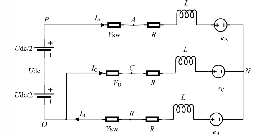
Figure 1. Motor equivalent diagram
When the motor is running, it recognizes electrical power from the power supply and transmits torque to a rotor to complete the magnetic flux of air gap. This power is an electromagnetic power,  , which is equal to the entirety of the products of the opposing potentials of the three-phase windings and the phase currents.
| 
| (5) |
Neglecting the stray and rotor mechanical loss, the air-gap power is transformed into rotor kinetic energy.
| 
| (6) |
Where,  is the motor's torque;
  is a mechanical angular velocity. The machine's formula of motion can be articulated as
| 
| (7) |
Where,  is the burden torque;
  is the motor rotor moment of inertia;
  is the viscous friction coefficient.
The above mathematical model (Equation (1) to Equation (7)) depicts the electrical and mechanical characteristics of the BLDC motor. According to this model, the PWM inverter module generates switching voltages for the motor phases, while the rotor position sensor model provides commutation information for switching the phases and closed-loop speed control.
PWM Control of the Inverter
In the BLDC engine drive scheme, the inverter switching signals are generated utilizing a PWM method to regulate the generated power used to the engine points. The PWM boss compares a reference control signal acquired from the speed boss with a high-frequency triangular carrier signal. Established this correspondence, changing pulses are produced to control the capacity of semiconductor schemes in the inverter. When the citation signal is higher in amount, the shipper indicates that the matching inverter switch is turned ON; alternatively, it is off. This process generates an order of pulses whose charge phase varies in accordance with the control indicated to create a piece boss. The duty cycle  decides the active manufacturing potential used for the motor and may be articulated as
| 
| (8) |
where  is the switch conduction time and
  , is the switching period.
Modeling a Motor Position Sensor
In a BLDC motor, the position detector detects the location of rotor poles and provides precise substitution information to the logic switching circuit [33]. This information converts the rotor magnetic pole location indication into an electrical indication to control the stator winding commutation. Figure 2 shows the schematic diagram of a 3-phase full-bridge drive circuit. If a 2-by-2 conduction circuit is used, in this mode, every period the rotor rotates 60 degrees, the inverter bridge commutates, and the stator magnetic state changes accordingly. Since two power transistors are simultaneously conducting at all times, the motor has six states, each with two phases conducting [34][35]. In order, they are T6T1, T1T2, T2T3, T3T4, T4T5, T5T6, and so on. The substitution logic, itemized according to the conduction order, is displayed in Table 1. Table 1 illustrates three switching states: "1" for positive DC bus connections, "−1" for negative DC bus connections, and "0" for floating or unenergized phases.
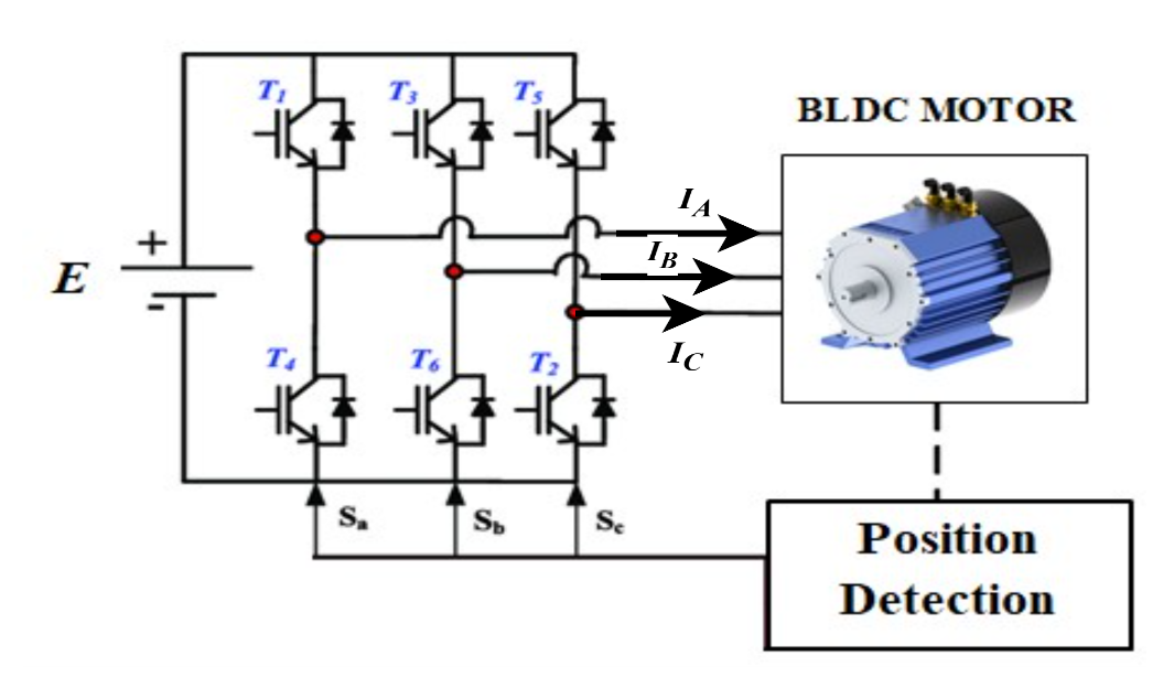
Figure 2. 3-phase full-bridge drive circuit
Table 1. Logical relationship diagram
State | A | B | C | Logical value |
T6T1 | 1 | -1 | 0 | 001 |
T1 T2 | 1 | 0 | -1 | 010 |
T2T3 | 0 | 1 | -1 | 011 |
T3T4 | -1 | 1 | 0 | 100 |
T4T5 | -1 | 0 | 1 | 101 |
T5T6 | 0 | -1 | 1 | 110 |
Rotor pre-positioning, only after determining the rotor's position at rest, can decide which two switching devices should be activated first during startup. This process of determining the rotor's initial position is typically called positioning [36]. The positioning method used in this chapter is the two-phase energization method, which applies forced traction by energizing any two phases. Because the motor's starting torque is relatively small, the starting current is controlled within a small range. Its specific value can be adjusted through experimental testing. The rotor pre-positioning step was accomplished in MATLAB/Simulink by energizing two phases for about 0.02 seconds before the regular commutation began. To avoid beginning torque and current spike, the initial current at the start of positioning was kept to roughly 20-25% of the rated current. This technique resulted in a reliable rotor alignment and the proper commencement of the commutation sequence. After energizing for a period of time, the rotor will rotate to the predetermined position corresponding to that energization state, thus completing the rotor positioning. Figure 3(a) shows the stator and rotor magnetic fields when phases A and B are energized. Interpreting the right-hand screw rule, the combined stator magnetomotive force  can be obtained. If the rotor magnetomotive force
  is at the position displayed in Figure 3(a), the rotor will rotate 120° clockwise to align with the motion of the stator electromagnetic field. Before the positioning current is applied, the position of the motor rotor is random, and its magnetic field direction may be at any position. If the rotor magnetomotive force is exactly in the reverse direction to in Figure 3(a) before phases A and B are energized, a misalignment will occur between the stator and rotor. The interaction prevents the rotor from moving. To avoid this problem, a DC power supply can be utilized twice, as displayed in Figure 3(b). First, the AC phases are energized to form the stator magnetomotive force . Even if the rotor magnetomotive force is at the position shown in Figure 3(b), the rotor will be pulled to the position of . Then, the AB phases are energized as shown in Figure 3(a), which ensures that the rotor reaches the expected designated position.
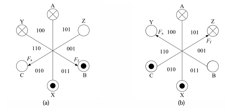
Figure 3. Rotor positioning diagram
PID Control of BLDC Motor
Because a PID controller can simultaneously employ two or more control modes, and different control parameters significantly vary the controller's overall control capabilities, it is essential to determine the controller parameters that optimize system control performance. Through in-depth research in control theory and continuous summarization of practical experience, control factor tuning approaches are categorized into theoretical tuning and production tuning [20]. Theoretical tuning of control parameters requires a specific mathematical model of the controlled object. However, controlled objects are often complex in structure and have numerous influencing factors, making accurate mathematical models difficult to obtain. Therefore, theoretical tuning methods such as the root locus method and the logarithmic frequency scheme are not applicable. Furthermore, theoretical tuning of control parameters is very cumbersome to calculate, and often results in suboptimal control parameters due to the neglect of numerous influencing factors. The optimal control parameters are not suitable for more complex control objects [21]. Therefore, in the method of adjusting the control parameters of the controller, the production modification technique is usually utilized to adjust the control factors. The engineering tuning method uses known control experience as the basis for parameter adjustment, and this tuning adjustment method can observe the response curve of the model at any time and further adjust the control factors according to the control effect until the control parameters meet the requirements of use [26]. As shown in Figure 4, the PI process is
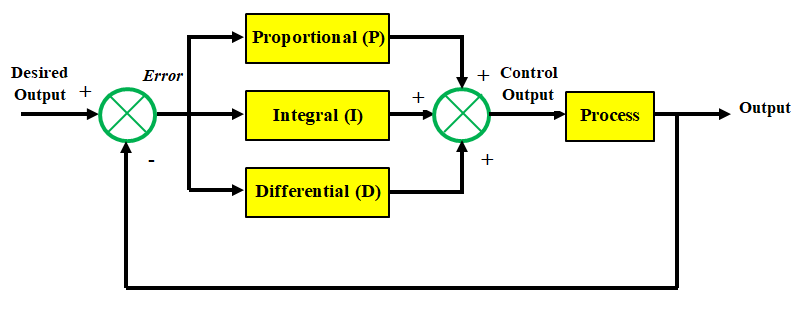
Figure 4. PID controller structure diagram
As displayed in the Figure 4 upstairs, the scheme deviation error is attained after the difference operation between the expected value, the desired output, and the system output value. The PID controller accomplishes proportional ( ), integral (
 ), and differential () operations on the deviation to obtain the input control quantity of the regulated process. A mathematical expression for the control action has been added in the PID control section as follows: The control mechanism indication.
  The PID controller is defined as:
| 
| (9) |
Where,  is the speed error between the orientation speed and the restrained speed,
  ,
,  , and
, and  are the proportional, integral, and derivative gains, respectively.
Fuzzy PID Control of Brushless Motors
The concept of "fuzzy" refers to the general perception of things in daily life by humans, such as the distance, the taste of dishes, and the age. Fuzzy logic control (FLC) is also called fuzzy control. When establishing fuzzy control, it is necessary to determine the output domain, the establishment of fuzzy language variables, and the method of fuzzy logic and fuzzy rule reasoning. Fuzzy control algorithms mainly imitate human thinking patterns, so there is no need for a mathematical model of the control object. Fuzzy control has a certain degree of intelligence. The core of fuzzy control is FLC rules and the language that represents the controlled object. Among them, the rules of fuzzy control are created on the thinking mode of humans in daily life and the experience gained by experts. Fuzzy control combines fuzzy theory and traditional control theory. Using fuzzy control can solve problems that cannot be solved well using traditional control methods. In recent years, the theory of fuzzy control has gradually matured, and the corresponding application fields have become more extensive. The control effect of the FLC is better than that of conventional control methods, and it has important significance in the field of artificial intelligence control [27],[37]. As displayed in Figure 5, the FLC process is as follows: fuzzy processing of input variables (fuzzification); associating the input fuzzy variables with fuzzy rules (knowledge base) (fuzzy reasoning); processing the obtained fuzzy output variables, and finally outputting specific parameters and sending them to the controlled object (clarification).
- Fuzzification: Converting the precise input into a set of fuzzy quantities.
- Fuzzy reasoning: The output fuzzy variables are usually represented by the input fuzzy variables and fuzzy rules, and are usually represented by multiple fuzzy rules. The output is a fuzzy quantity, and this fuzzy quantity is described by a membership function.
- Explanation: The purpose of explanation is to transform the fuzzy output into a specific output. (4) Knowledge base: The information in the knowledge base includes membership functions [38][39], the domain of output parameter changes, the criteria for converting fuzzy variables into specific variables, and control rules for different control parameters.
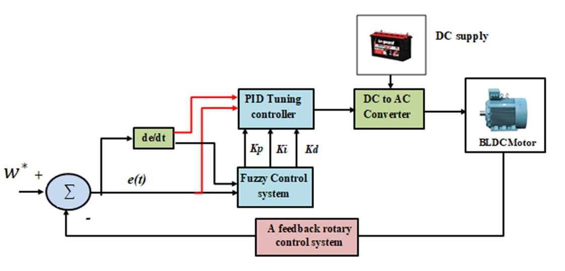
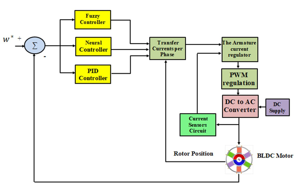
Figure 5. Schematic illustration of the suggested control scheme
The operating principle of this regulator is as follows: A speed sensor detects the current speed of the BLDCs in real time [40]. The speed deviation change rate, ,
,  , is calculated by subtracting the current speed from the set speed. These two values serve as inputs to the fuzzy controller, which then outputs three PID parameters: , , and . Fuzzy rules are used to output different PID parameters in real time. These rules are derived from expert experience and practical experience [41][42]. The behavior of the fuzzy system determines the accuracy of the entire BLDC control mechanism system. Developing complete and effective fuzzy rules is a prerequisite for achieving high efficiency in fuzzy control methods. An efficient control system requires experienced and effective fuzzy control rules [43]. Therefore, high-quality control rules are paramount for efficient BLDC drives and regulation. The fuzzy rules for the fuzzy PID controller specified in this paper are shown in Figure 6 and Figure 7.
| 
|
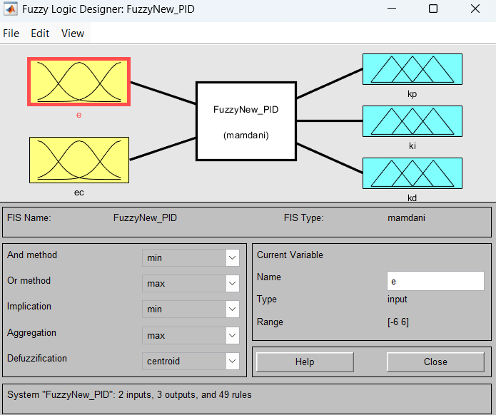
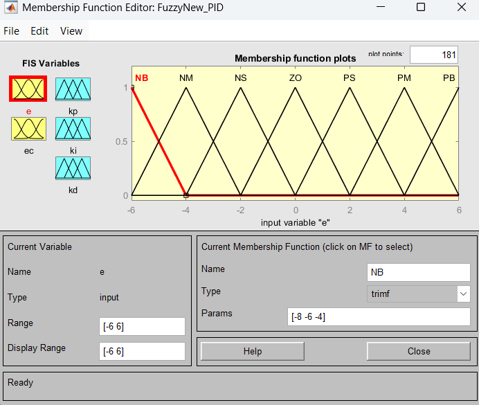
Figure 6. Membership Function Editor
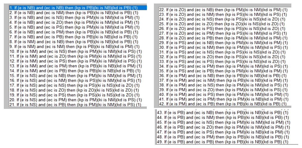
Figure 7. Fuzzy Rule Editor
Fuzzy Membership Functions and Rule Design
In the proposed fuzzy PID controller, two input variables are used: the speed error e and the rate of variation of error . The control outputs three restrictions matching the PID yield , , and [44][45]. Each recommendation changeable is planned into semantic variables using three-cornered enrollment functions. The universe of discourse for both inputs is defined in the range [−6,6][-6,6][−6,6], as shown in the membership function editor in Figure 6. Seven linguistic terms are utilized to signify the input variables: NB (Negative Big), NM (Negative Medium), NS (Negative Small), ZO (Zero), PS (Positive Small), PM (Positive Medium), PB (Positive Big).
Triangular enrollment functions are picked because they determine a good balance between computational clarity and command precision. These functions likewise allow smooth changes between abutting fuzzy sets, which improves boss establishment.
Fuzzy Rule Base Construction.
The rule base consists of 49 rules (7 × 7), which are built based on established expert control information and the active behavior of the BLDC engine. The rules are created to regulate the PID limits adaptively in accordance with the size and flow of the speed error [46][47]. If e is PB and is PB, therefore a best equivalent gain is applied to quicken the adjustment of the abundant helpful wrong If is nearly nothing and is limited, the boss reduces and to prevent oscillations and advance steady-state strength If the wrong is narrow but changeful briskly, the derivative gain increases to restrain omit This construction admits the FLC to dynamically adjust the PID gains and embellish the changeability of the speed control whole [48].
Impact of Membership Function Selection: The shape and classification of the enrollment functions considerably influence the boss depiction. Narrower enrollment functions increase subtlety to limited changes in error, but granting permission brings about oscillations. Conversely, roomier participation functions produce more flowing control conduct but concede the possibility decrease reaction speed [49]. Therefore, the picked three-cornered membership functions support a compromise between openness and cohesion. Adjusting the participation function limits can increase the establishment period, weaken omission, or enhance upset denial contingent upon the control objective.
Defuzzification Method: The fuzzy deduction system uses the Mamdani conclusion means and the centroid (center of gravity) defuzzification method. The centroid procedure calculates the fresh output worth in accordance with:
| 
| (10) |
Where  shows the amassed enrollment function of the output changing. This pattern is a usual cause because it determines smooth and resistant production principles, which are acceptable real-freedom engine control requests.
PID gains are adaptively adjusted using FLC using two inputs: speed error and change in speed error. The triangle membership functions were selected because of their straightforward calculation and lack of response instability. To improve dynamic reaction and disturbance rejection under various working situations, the rule foundation was created using FLC knowledge from the expert control knowledge.
Neural Network Design
Neural networks (NNs) are the product of the integration of NNs. They combine the benefits of NN theory, integrating learning, suggestion, appreciation, and information processing. This combination aims to solve the fuzzy or uncertain problems that traditional fuzzy methods find difficult to handle [50]. Spiking neural network structure. Generally, according to whether the network structure changes, spiking neural networks can be divided into static spiking neural networks and dynamic spiking neural networks. Static spiking neural networks refer to networks that only change parameters, such as weights, during training, without changing the number of neurons and layers in the network; dynamic spiking neural networks not only change weights during training, but also dynamically adjust the number of neurons and the connection mode. The network construction is displayed in Figure 8. Since the system structure adopts unsupervised learning rules for learning, an inhibition layer is introduced for competition, which can increase the weight of the winning neuron and reduce the weight of other neurons, effectively reducing the noise in the training process and obtaining better training results.
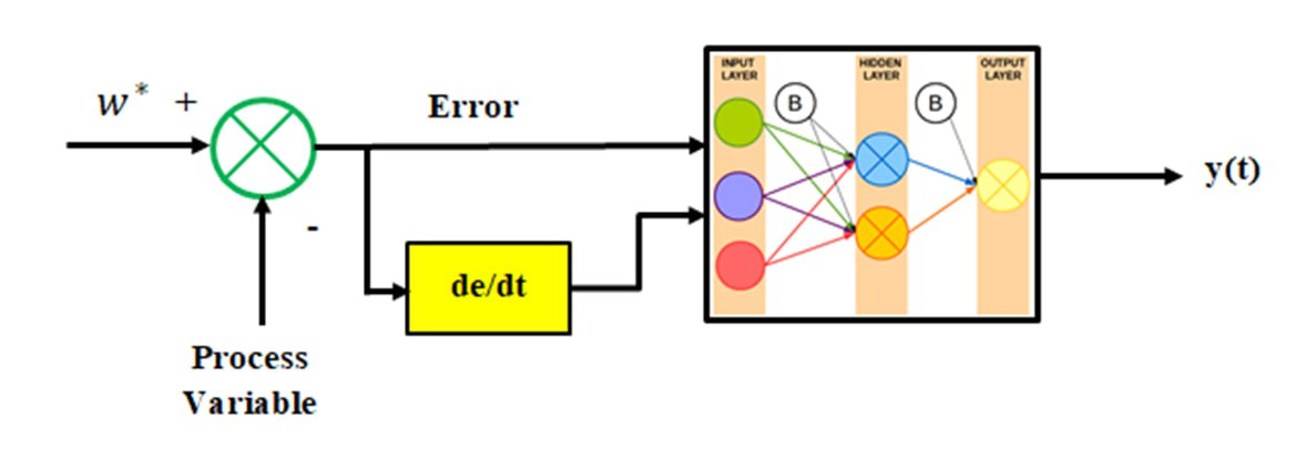
Figure 8. Neural network structure diagram
In designing the neural network controller for this research, it was decided to utilize an MLP architecture to enhance the adaptability of the BLDC motor speed supervisor. The structure of the NN encompasses three layers: input layer, hidden layer, and output layer. The input layer has two indications coming from the control systems:
|
| (11) |
| 
| (12) |
Where  signifies the speed error and
  denotes the rate of variation of the error.
The interconnected system boss is planned to mirror a PID control device through two affecting animate nerve organs substitute-controllers: Neural PI superior and Neural PD superior. The PI affecting the animate nerve organs boss produces the proportional–integral element of the control operation, while the PD affecting the animate nerve organs boss produces the proportional–derivative factor. By joining these two factors, the general command behaves similarly to a classic PID controller.
The overall control signal can be articulated as
| 
| (13) |
Where,
| 
| (14) |
| 
| (15) |
The neural network dynamically adjusts the effective gains. , , and based on the system state, improving adaptability to load disturbances and parameter variations.
The interconnected system is prepared utilizing a directed education approach. During preparation, the grid adjusts its weights to understate the error at the midpoint between two points: the requested output and the concluded productivity. The penalty function for secondhand preparation is the mean squared error (MSE):
| 
| (16) |
Where  represents the desired output and
  represents the network output.
The weights are restored utilizing the slope-lowering innovation in accordance with
| 
| (17) |
Where,  is the connection weight between neurons,
  is the learning rate,
  represents the iteration step.
A detailed comparison table between the different intelligent PID control strategies has been added in Table 2.
Table 2: Identification of Intelligent PID Control Approaches for BLDC Motor Speed Control
Controller Type | Control Principle | Adaptation Mechanism | Advantages | Limitations | Performance in This Study |
Conventional PID | Fixed proportional, integral, and derivative gains | No adaptive control mechanism | Simple structure, easy implementation | Poor adaptability to load variations, higher torque ripple | Largest speed error and highest torque ripple |
Fuzzy PID | Fuzzy logic is used to adjust PID gains based on error and error change | Rule-based adaptation using fuzzy inference | Handles nonlinearities better than conventional PID, improved stability | Requires expert rule design and tuning of membership functions | Reduced speed error and lower torque ripple than PID |
NN-PID | Neural network adjusts PID parameters dynamically | Learning-based adaptive tuning of controller parameters | High adaptability, improved response time, reduced torque ripple | Requires a training process and higher computational complexity | Best performance with the lowest speed error and minimum torque ripple |
Table 3 summarizes the functional description of the suggested hybrid fuzzy-neural PID controller for BLDC motor speed regulation. The Table 3 provides an overview of each subsystem's function and operation in the suggested control architecture. It explains how the adaptive PID tuning mechanism, FLC, NN adaptation block, error calculation block, PWM inverter, and BLDC motor feedback circuit are related.
Table 3. Describes the functional characteristics of the suggested hybrid FLC-NN PID controller
Component | Function | Inputs | Outputs | Contribution |
Error Calculation | Computes speed deviation | 
| ( ) ) | Generates control variables |
Fuzzy Logic Controller | Rule-based adaptive tuning | () | Preliminary PID adjustments | Handles nonlinear behavior |
Neural Network Block | Learns system dynamics | () | Adaptive correction factors | Improves adaptability |
PID Gain Tuning | Updates ( ) ) | Fuzzy + NN outputs | Optimized gains | Enhances response quality |
PID Controller | Generates a control signal | Speed error | Control voltage | Regulates motor speed |
PWM Inverter | Produces switching pulses | Control signal | Inverter voltage | Controls motor power |
BLDC Motor | Controlled plant | Inverter voltage | Rotor speed | Mechanical output |
Feedback Loop | Measures actual speed | Motor speed | Feedback signal | Closed-loop stabilization |
PID factor tweaking, the NN module was implemented as an adaptive feed-forward network. The network receives the speed error and error variation as input signals, and the controller's gains are modified in accordance with the BLDC motor's nonlinear operating characteristics. The mean squared error between the reference speed and the actual speed will be minimized by the adaptive learning process. The training flow chart of network connection probability is displayed in Figure 9:
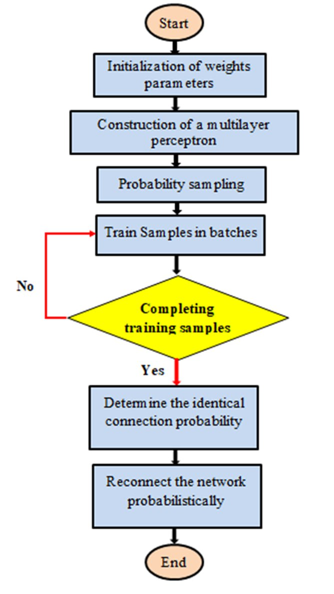
Figure 9. Network connection probability flow chart
Figure 10 shows a block diagram of the BLDC machine model, which primarily includes the BLDC main module, voltage inverter module, current hysteresis control mechanism module, speed control mechanism module, and orientation current module. In a BLDC motor control system, the controller generates motor speed and direction control signals based on the control approach. A position detector generates a position signal representing the motor rotor. The electronic commutator logically synthesizes the rotor position signal, motor speed regulation, and direction control signals to generate corresponding switching signals. These switching signals trigger the inverter's power switches in a specific sequence, distributing power to the motor stator's 3-phase coils through a specific logical relationship, enabling the machine to generate continuous torque. The following is a detailed description of each module's function.
A virtual prototype model of the BLDC motor drive system was built in MATLAB/Simulink to examine the dynamic performance of the suggested PID, fuzzy PID, and NN-PID control techniques under various operating situations. To aid in motor analysis and controller vectoring, the virtual prototype integrates a motor mathematical model, PWM inverter, rotor-position sensor, and intelligent control algorithms into a single simulation environment.
Figure 10. Schematic diagram of BLDC vector control system
RESULTS AND DISCUSSION
The simulation results supply the main insights into the influence of the projected control planning for BLDC engine speed regulation. Although MATLAB/Simulink was used as the simulation platform, the major objective of the imitation is to judge the active act of the control algorithms under variable load conditions. The results display that the common PID boss exhibits comparatively large speed error and greater torque ripple when unexpected load disturbances are introduced. When FLC is joined with the PID controller, the system shows revised changeability and shortened constant-state error due to the skill of the fuzzy machine to regulate the controller limits in accordance with the wrong and allure rate of change. The suggested NN-PID boss further improves method efficiency by providing adaptive bringing into harmony of the control limits through the interconnected system makeup. As a result, the weapon speed reception improves faster, the speed error is substantially minimized, and the turn ripple is diminished. These results display that the neural-network-based controller can better handle nonlinear traits and limit differences of the BLDC motor distinguished by common control suggestions. This paper establishes a simulation model of a BLDCM closed-loop speed system created on MATLAB/Simulink and performs simulations on the model. In the simulation, the BLDCM motor parameters are represented as follows:  = 0.194Ω (stator winding resistance per phase), = 0.097mH (self-inductance per phase), = 0.062mH (mutual inductance), = 0.0027 kg•m² (moment of inertia),
  = 0.0004 Nm•s/rad (damping coefficient), rated speed
  = 475rpm, pole pair number
  = 8, and a 300 V DC power supply. The speed PID controller parameters are set as = 0.06, Ki = 35, and =2.5.
Results with PID
To check the dynamic behavior of the designed BLDC speed control simulation model, the system was started with no load. After entering steady state, a load torque of 5.6 Nm was suddenly applied at  = 0.2 s. The load torque was suddenly reduced to 2.5 Nm at = 0.4 s. The simulation curve of system speed is displayed in Figure 11. As demonstrated in Figure 11, the BLDC motor speed response curve reaches its peak at 475 rpm at 0.05s, and the overshoot ranges from 655.556 to 417.5 rpm, after oscillations. After the load is added, 0.2s later, the system's speed response time is 0.26s. At time 0.4s, the overshoot ranges from 492.97 to 468.15 rpm. For the simulations, the reference motor speed was set to 475 rpm, with a load torque step of 2.5 Nm to 5.6 Nm.
Figure 12 shows the error in speed with PID at time 0.2s. The error ranges from 38.5 to -13.474 rpm. At time 0.4 s, the error ranges from 6.3 to -19.1 rpm. The error value is large, and the process of settlement time is longer. For the simulations, the reference motor speed was set to 475 rpm, with a load torque step of 2.5 Nm to 5.6 Nm. Figure 13 depicts a comparison of the dynamic performance of the PID approach. At = 0.2s, the load torque of the BLDC motor changes from 5.6 Nm to 2.5 Nm while operating at its rated speed of 475 rpm. As demonstrated in Figure 13, when the load changes abruptly, the system completes the torque reaction. Traditional PID has a large ripple of 74.56%. For the simulations, the reference motor speed was set to 475 rpm, with a load torque step of 2.5 Nm to 5.6 Nm.
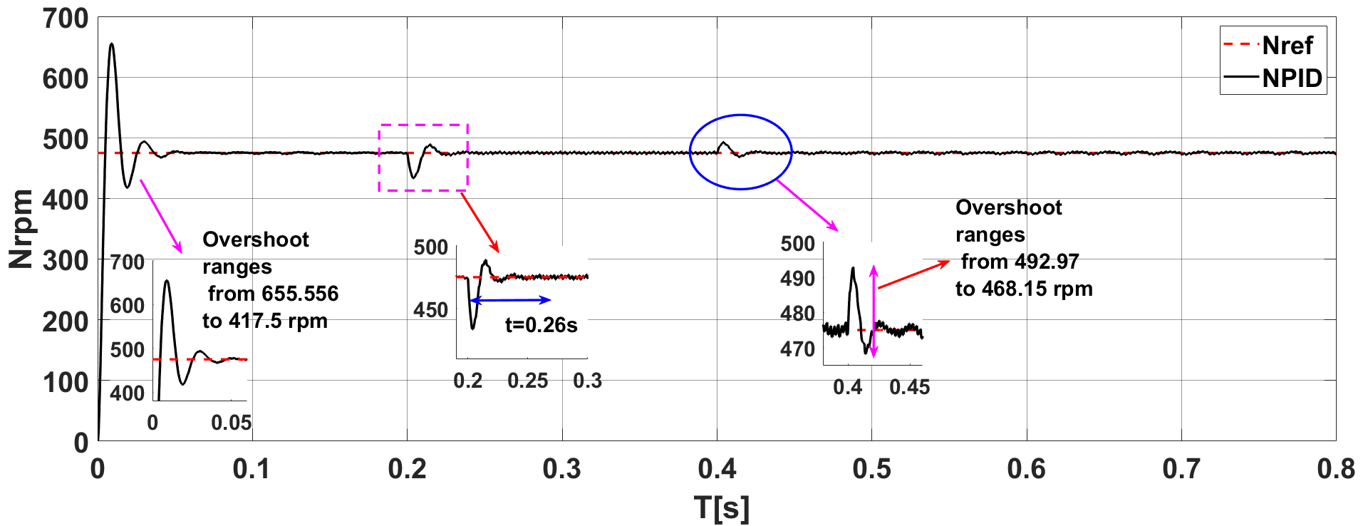
Figure 11. Speed response curve
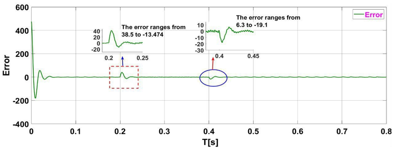
Figure 12. shows the error of speed with PID
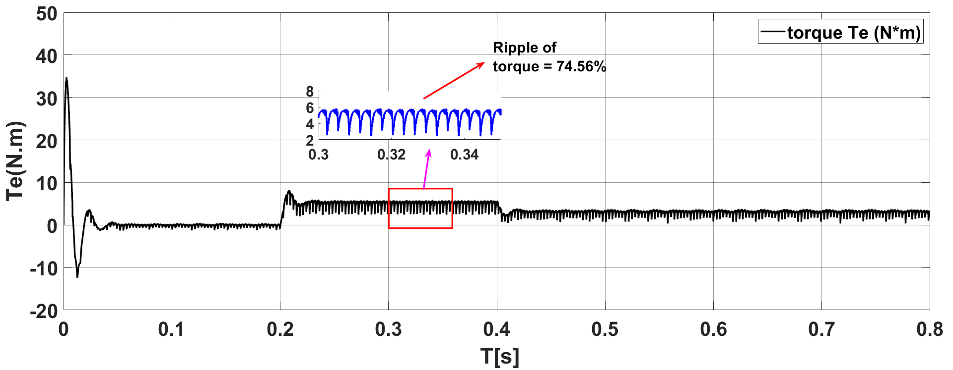
Figure 13. shows the torque with PID
Results with Fuzzy
The simulation curve of system speed is displayed in Figure 14. As depicted in Figure 14, the brushless DC motor speed response curve reaches its peak at 475 rpm at 0.03 s, and the overshoot ranges from 508.12 to 475 rpm, after oscillations. After the load is added, 0.2s later, the system's speed response time is 0.245s. At time 0.4s, the overshoot ranges from 483.21 to 472.84 rpm. For the simulations, the reference motor speed was set to 475 rpm, with a load torque step of 2.5 Nm to 5.6 Nm.
Figure 15 shows the error in speed at 0.2s with fuzzy. The error ranges from 22.5 to -0.305 rpm. At time 0.4 s, the error ranges from 1.41 to -7.7 rpm. The error value is low. The settlement process is less than the PID method, according to the simulation results. For the simulations, the reference motor speed was set to 475 rpm, with a load torque step of 2.5 Nm to 5.6 Nm. Figure 16 depicts a comparison of the dynamic performance of the fuzzy approach. At = 0.2s, the load torque of the BLDC motor changes from 5.6 Nm to 2.5 Nm while operating at its rated speed of 475 rpm. As demonstrated in Figure 16, when the load changes abruptly, the system completes the torque reaction. The improved PID using Fuzzy has a ripple of less than 68.3%. For the simulations, the reference motor speed was set to 475 rpm, with a load torque step of 2.5 Nm to 5.6 Nm.
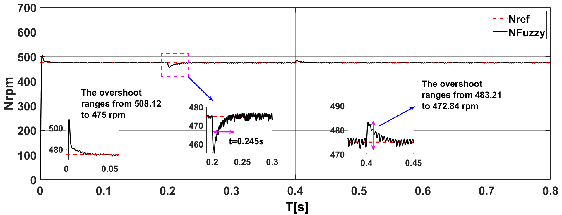
Figure 14. Speed response curve with fuzzy
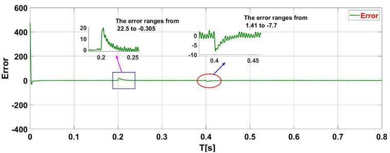
Figure 15. shows the error in speed due to the fuzzy
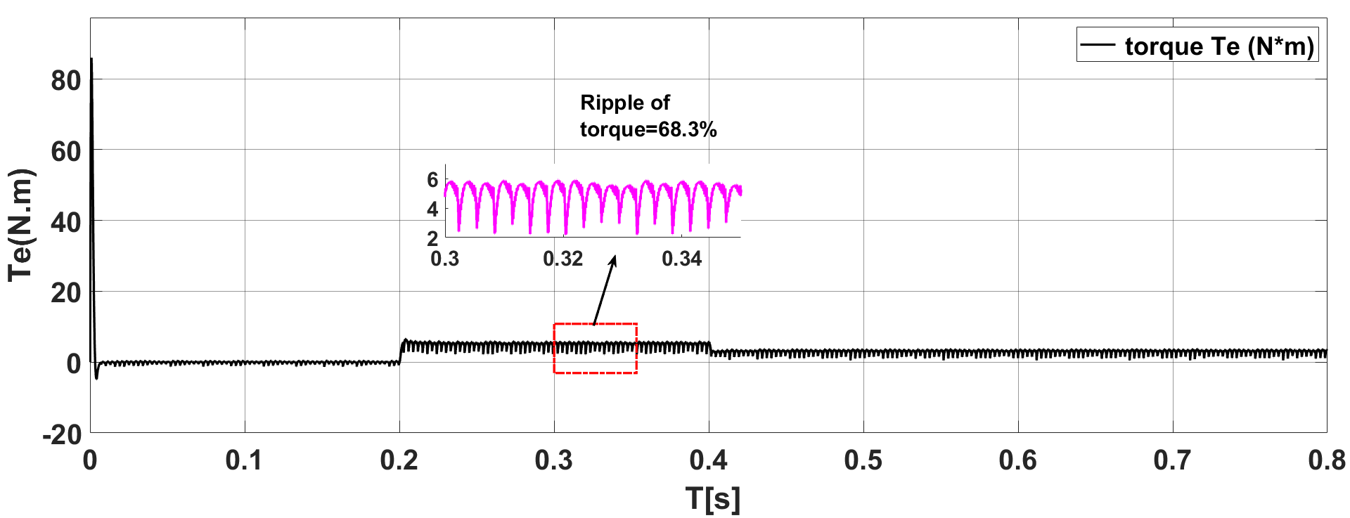
Figure 16. shows the torque of speed with fuzzy
Results with NNs
The simulation curve of system speed is displayed in Figure 17. As depicted in Figure 17, the brushless DC motor speed response curve reaches its peak at 475 rpm at 0.021 s, and the overshoot ranges from 508.32 to 475 rpm, after oscillations. After the load is added, 0.2s later, the system's speed response time is 0.236s. At time 0.4s, the overshoot ranges from 482.201 to 473.25 rpm. For the simulations, the reference motor speed was set to 475 rpm, with a load torque step of 2.5 Nm to 5.6 Nm.
Figure 18 shows the error in speed with NNs at time 0.2s. The error ranges from 22.3 to -0.102 rpm. At time 0.4 s, the error ranges from 0.98 to -8.2 rpm. The error value is lower than that of the PID method. The settlement process is less than the PID method, according to the simulation results. For the simulations, the reference motor speed was set to 475 rpm, with a load torque step of 2.5 Nm to 5.6 Nm. Figure 19 depicts a comparison of the dynamic performance of the NNs and the PID approach. At = 0.2s, the load torque of the BLDC motor changes from 5.6 Nm to 2.5 Nm while operating at its rated speed of 475 rpm. As demonstrated in Figure 19, when the load changes abruptly, the system completes the torque reaction. The improved PID using NNs has a low ripple of 64.13%. The simulation results prove that the NN method is much better than the PID and Fuzzy regulators in terms of reaction time, speed error value, and torque ripple. For the simulations, the reference motor speed was set to 475 rpm, with a load torque step of 2.5 Nm to 5.6 Nm.
The comparison findings demonstrate that the NN-PID controller outperforms fuzzy and conventional PID controllers in terms of dynamic performance. Due to its intrinsic features and inability to adjust to various control gains, the traditional PID controller exhibited the highest torque ripple (74.56%) and the biggest speed-error variances under various load situations. The fuzzy PID controller achieved a torque ripple of around 68.3% while improving system stability through rule-based adaptive tuning. In contrast, the suggested NN-PID controller performed the best overall due to its quick reaction time, lower steady state speed error, and lowest torque ripple of about 64.13%. The neural network's capacity to learn and modify the controller settings in reaction to the nonlinear operating circumstances of the BLDC motor system is the main factor behind this improved performance. Based on the findings derived from the simulation outcomes, Table 4 presents the error metrics associated with speed, torque fluctuation, and response duration employing various simulation techniques.

Figure 17. Speed response curve with NNs
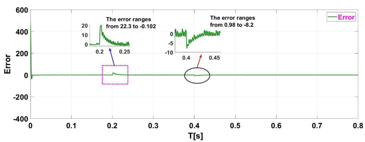
Figure 18. shows the error of speed with NNs
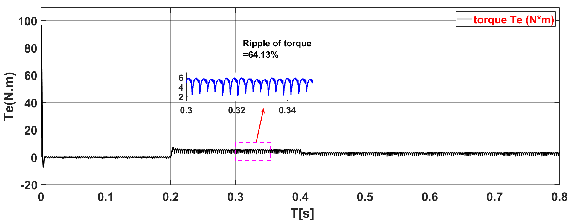
Figure 19. shows the torque of speed with NNs
Table 4 shows the comparison between the three methods.
Results | PID | Fuzzy | NNs |
response time at 0.2s for speed | 0.26s | 0.245s | 0.236s |
Error at time 0.2s for speed | 38.5 to -13.474 | 22.5 to -0.305 | 22.3 to -0.102 |
Error at time 0.4s for speed | 6.3 to -19.1 | 1.41 to -7.7 | 0.98 to -8.2 |
Ripple of toque | 74.56% | 68.3% | 64.13% |
Performance | Less | Good | Best |
The suggested hybrid fuzzy-neural PID controller performs better overall than the previously published BLDC motor control techniques, according to the comparison data in Table 5. When compared to the other approaches, the suggested controller has the lowest torque ripple (64.13%), reaction time (0.20 s), and steady state speed error. In contrast to traditional PID controllers with fixed gains and fuzzy controllers that primarily rely on predefined rule sets, the suggested NN-PID approach is based on adaptive fuzzy logic and the learning capacity of neural networks, which enables better nonlinear compensation and adaptability in various load conditions. The outcomes show that the suggested intelligent control technique for BLDC motor speed regulation is reliable and effective. Table 5 shows the Comparison Between the NN-PID Controller and Previous Studies
Table 5. Comparative Analysis Between the Proposed NN-PID Controller and Previous BLDC Motor Control Studies
Ref. | Control Method | Main Objective | Response Characteristics | Torque Ripple Performance |
[51] | Hybrid Fuzzy Logic + Adaptive SVM | Torque ripple reduction in PM-BLDC drives | Improved dynamic response with smoother commutation | Significant torque ripple reduction reported |
[52] | Fuzzy-Based Sliding Mode Control | Torque ripple suppression under variable-speed operation | Improved robustness against disturbances | Reduced ripple and harmonic distortion |
[53] | DGOA-Optimized FOPID Controller | Speed regulation and ripple minimization | Faster transient response compared with PI control | Reduced the torque ripple factor |
[54] | Fuzzy Active Disturbance Rejection Control | Torque pulsation suppression in PMSM drives | Improved dynamic stability | Reduced torque pulsation under complex conditions |
[55] | Neuro-Fuzzy Nonlinear PID | Speed tracking improvement for EV BLDC systems | Improved nonlinear compensation and disturbance rejection | Enhanced adaptive response |
Proposed Study | Hybrid Fuzzy–Neural PID Controller | Simultaneous speed-error reduction and torque-ripple mitigation | Fast response with reduced steady-state error (±0.102 rpm) | Torque ripple reduced to 64.13% under identical operating conditions |
CONCLUSIONS
BLDC motors are extensively utilized in industry, transportation, and other high-precision applications due to their simple structure, reliable operation, and excellent speed regulation capability. This paper first uses MATLAB to build a virtual prototype model and simulates it with the brushless DC motor model. The virtual prototype's control requirements for the BLDC motor are determined and implemented. The BLDC motor's control scheme is a closed-loop control system with internal feedback for speed control. Finally, simulations of the virtual prototype using traditional PID, fuzzy PID, and NN-PID are performed in MATLAB, and the simulation results are compared. The proposed control method was compared via simulation in MATLAB/Simulink. The simulations verified that the NN-PID control algorithm drives the motor more efficiently than the traditional PID algorithm, fuzzy PID control, improving motor speed regulation and overall system stability, and reducing the ripple in the torque. The torque-ripple ratio of the typical PID, fuzzy PID, and NN-PID controllers was around 74.56%, 68.3%, and 64.13%, respectively. The NN-PID controller produced the minimum torque ripple due to its improved nonlinear control performance and adaptive learning ability. The simulation results demonstrate the effectiveness of the proposed approach in reducing speed, error, and torque ripple. Future work will devote effort to enhanced methods, a degree, historical algorithms, or atom swarm optimization, such as genetic algorithms or particle swarm optimization, for optimal tuning of controller parameters. Another potential direction is the unification of advanced deep learning techniques to improve adaptive control behavior under variable load conditions and limit doubts. Future studies will focus on Hardware-in-the-Loop (HIL) testing to further evaluate practical viability and industrial applicability, as well as real-time implementation and experimental testing of the suggested controller in the DSP/FPGA platform.
REFERENCES
- Wang X, Wu X, Cheng S, Shi J, Yue W, “Design and experiment of control architecture and adaptive dual-loop controller for brake-by-wire system with an electric booster,” IEEE Trans Transp. Elect. vol. 6, no. 3, pp. 1236–1252, 2020, https://doi.org/10.1109/TTE.2020.3010279.
- J. Pakdeeto, S. Wansungnoen, K. Areerak, and K. J. I. A. Areerak, “Optimal speed controller design of commercial BLDC motor by adaptive Tabu search algorithm,” IEEE Access, vol. 11, pp. 79710–79720, 2023, https://doi.org/10.1109/ACCESS.2023.3300233.
- Y. K. Poudel and P. Bhandari, ‘‘Control of the BLDC motor using ant colony optimization algorithm for tuning PID parameters,’’ Arch. Adv. Eng. Sci., vol. 2, no. 2, pp. 108–113, 2024, https://doi.org/10.47852/bonviewAAES32021184.
- Gobinath S, Madheswaran M, “Deep perceptron neural network with fuzzy PID controller for speed control and stability analysis of BLDC motor,” Soft Computing, vol. 24, no. 13, pp. 10161–10180, 2020, https://doi.org/10.1007/s00500-019-04532-z.
- A. Damiano, A. Floris, G. Fois, I. Marongiu, M. Porru, and A. Serpi, “Design of a high-speed ferrite-based brushless DC machine for electric vehicles,” IEEE Trans. Ind. Appl., vol. 53, no. 5, pp. 4279–4287, 2017, https://doi.org/10.1109/ICELMACH.2016.7732605.
- G. Scelba, G. De Donato, M. Pulvirenti, F. Giulii Capponi, and G. Scarcella, “Hall-effect sensor fault detection, identification, and compensation in brushless DC drives,” IEEE Trans. Ind. Appl., vol. 52, no. 2, pp. 1542–1554, 2016, https://doi.org/10.1109/TIA.2015.2506139.
- J. S. Park and K. Lee, “Online advanced angle adjustment method for sinusoidal BLDC motors with misaligned hall sensors,” IEEE Trans. Power Electron., vol. 32, no. 11, pp. 8247–8253, 2017, https://doi.org/10.1109/TPEL.2017.2694042.
- S. Tsotoulidis and A. N. Safacas, “Deployment of an adaptable sensorless commutation technique on BLDC motor drives exploiting zero sequence voltage,” IEEE Trans. Ind. Electron., vol. 62, no. 2, pp. 877–886, 2015, https://doi.org/10.1109/TIE.2014.2334654.
- G. Liu, C. Cui, K. Wang, B. Han, and S. Zheng, “Sensorless control for high-speed brushless DC motor based on the line-to-line back EMF,” IEEE Trans. Power Electron., vol. 31, no. 7, pp. 4669–4683, 2016, https://doi.org/10.1109/TPEL.2014.2328655.
- L. Yang, Z. Q. Zhu, H. Bin, Z. Zhang, and L. Gong, “Virtual Third Harmonic Back EMF-Based Sensorless Drive for High-Speed BLDC Motors Considering Machine Parameter Asymmetries,” in IEEE Transactions on Industry Applications, vol. 57, no. 1, pp. 306-315, 2021, https://doi.org/10.1109/TIA.2020.3033821.
- L. Yang, Z. Q. Zhu, H. Bin, Z. Zhang, and L. Gong, "Safety Operation Area of Zero-Crossing Detection-Based Sensorless High-Speed BLDC Motor Drives," in IEEE Transactions on Industry Applications, vol. 56, no. 6, pp. 6456-6466, 2020, https://doi.org/10.1109/TIA.2020.3012594.
- X. Zhou, Y. Zhou, C. Peng, F. Zeng, and X. Song, “Sensorless BLDC motor commutation point detection and phase deviation correction method,” IEEE Trans. Power Electron., vol. 34, no. 6, pp. 5880–5892, 2019, https://doi.org/10.1109/TPEL.2018.2867615.
- W. Chen, Y. Liu, X. Li, T. Shi, and C. Xia, “A novel method of reducing commutation torque ripple for brushless DC motor based on Cuk converter,” IEEE Trans. Power Electron., vol. 32, no. 7, pp. 5497–5508, 2017, https://doi.org/10.1109/TPEL.2016.2613126.
- G. Jiang, C. Xia, W. Chen, T. Shi, X. Li, and Y. Cao, “Commutation torque ripple suppression strategy for brushless DC motors with a novel noninductive boost front end,” IEEE Trans. Power Electron., vol. 33, no. 5, pp. 4274–4284, 2018, https://doi.org/10.1109/TPEL.2017.2721439.
- R. K. Achary, S. Durgaprasanth, C. Nagamani, and G. S. Ilango, “A simple voltage modulator scheme for torque ripple minimization in a permanent magnet brushless DC motor,” IEEE Trans. Power Electron., vol. 35, no. 3, pp. 2809–2818, 2020, https://doi.org/10.1109/TPEL.2019.2926122.
- X. Yao, J. Zhao, J. Wang, S. Huang, and Y. Jiang, "Commutation Torque Ripple Reduction for Brushless DC Motor Based on an Auxiliary Step-Up Circuit," in IEEE Access, vol. 7, pp. 138721-138731, 2019, https://doi.org/10.1109/ACCESS.2019.2943411.
- A. H. Taha, R. K. Chillab, K. A. Jasim, A. H. Shaban, “Comparing Different Methods for Calculating Crystal Size, Strain and Crystallinity of LaBa2Cu3O7 Compound Using XRD Peak Broadening Analysis,” AIP Conference Proceedings, vol. 2437, no. 1, p. 020183, 2022, https://doi.org/10.1063/5.0093127.
- C. Ge, Z. Liu, L. Fang, H. Ling, A. Zhang, and C. Yin, "A Hybrid Fuzzy Convolutional Neural Network Based Mechanism for Photovoltaic Cell Defect Detection with Electroluminescence Images," in IEEE Transactions on Parallel and Distributed Systems, vol. 32, no. 7, pp. 1653-1664, 2021, https://doi.org/10.1109/TPDS.2020.3046018.
- Saif Talal Bahar and Raed A. Abd-Alhmeed, “Reduce-Complexity of Predictive Current Control for a 3-Phase Voltage Source Inverter,” Journal of Techniques, vol. 7, no. 3, pp. 16–25, 2025, https://doi.org/10.51173/jt.v7i3.2621.
- Y. Deng, Z. Ren, Y. Kong, F. Bao, and Q. Dai, “A hierarchical fused fuzzy deep neural network for data classification,” IEEE Trans. Fuzzy Syst., vol. 25, no. 4, pp. 1006–1012, 2017, https://doi.org/10.1109/TFUZZ.2016.2574915.
- M.-G. Gan, M. Zhang, C.-Y. Zheng, and J. Chen, “An adaptive sliding mode observer over a wide speed range for sensorless control of a brushless DC motor,” Control Engineering Practice, vol. 77, pp. 52–62, 2018, https://doi.org/10.1016/j.conengprac.2018.05.004.
- Y. Zhao, W. Qiao, and L. Wu, “Improved Rotor Position and Speed Estimators for Sensorless Control of Interior Permanent-Magnet Synchronous Machines,” IEEE Journal of Emerging and Selected Topics in Power Electronics, vol. 2, no. 3, pp. 627–639, 2014, https://doi.org/10.1109/JESTPE.2014.2298433.
- F. R. García, A. C. Andrade, G. E. Pérez, and L. A. Icaza, “Current tracking adaptive control of brushless DC motors,” International Journal of Adaptive Control and Signal Processing, pp. 1–14, 2026, https://doi.org/10.1002/acs.70032.
- D. S. Nair, G. Jagadanand, and S. George, “Sensorless direct torque controlled BLDC motor drive with Kalman filter algorithm,” in IECON 2017 - 43rd Annual Conference of the IEEE Industrial Electronics Society, pp. 2160–2165, 2017, https://doi.org/10.1109/IECON.2017.8216363.
- A. Attar, B. Jamal, and K. Grari, “Control of brushless dc motors using sensorless back-emf integration method,” Materials Today: Proceedings, vol. 45, no. 03 2021, https://doi.org/10.1016/j.matpr.2021.01.861.
- J. M. Liu and Z. Q. Zhu, “Improved sensorless control of permanent magnet synchronous machine based on third-harmonic back emf,” IEEE Transactions on Industry Applications, vol. 50, no. 3, pp. 1180-1187, 2014, https://doi.org/10.1109/TIA.2013.2284299.
- K. Soumia, H. Mohammed, “Optimization of PID Controller for Brushless DC Motor Based on Dung Beetle Algorithm,” Journal of Information Systems Engineering and Management, vol. 10, no. 465, 2025, https://doi.org/10.52783/jisem.v10i46s.8820.
- X. Song, B. Han, S. Zheng, and J. Fang, “High-Precision Sensorless Drive for High-Speed BLDC Motors Based on the Virtual Third Harmonic Back-EMF,” IEEE Transactions on Power Electronics, vol. 33, no. 2, pp. 1528–1540, 2018, https://doi.org/10.1109/TPEL.2017.2688478.
- G. Raju, G. N. Srinivas, “Intelligent Control Strategies for BLDC Motors in Electric Vehicles: Unveiling the Optimal Balance of Speed, Stability, and Efficiency,” International Journal of Applied and Computational Mathematics, vol. 11, no. 244, 2025, https://doi.org/10.1007/s40819-025-02069-4.
- H. Jin, G. Liu, and S. Zheng, “Commutation Error Closed-Loop Correction Method for Sensorless BLDC Motor Using Hardware-Based Floating Phase Back-EMF Integration,” IEEE Transactions on Industrial Informatics, vol. 18, no. 6, pp. 3978–3986, 2022, https://doi.org/10.1109/TII.2021.3113368.
- K. M. Wadi, R. K. Chillab, A. N. Abdulateef, K. A. Jasim, A. H. Shaban, M. A. Hassan, S. S. Jahil, “The effect of potassium substitution on the properties of HgBa2Ca2Cu3O8+δCompound,” Journal of Physics: Conference Series, vol. 1879, no. 3, p. 032064, 2021, http://doi:10.1088/1742-6596/1879/3/032064.
- G. Kaczmarczyk, M. Malarczyk, D.D. Ferreira, M. Kaminski, “Stable rules definition for fuzzy TS speed controller implemented for BLDC motor,” Appl. Sci., vol. 14, no. 3, p. 982, 2024, https://doi.g/10.3390/app14030982.
- M. K. Ismael, S. T. Bahar, and A. A. Abdullah, “Harmonic Elimination Method for Permanent Magnet Synchronous Motor Utilizing Active Disturbance Rejection Control,” Proceedings of Engineering and Technology Innovation, vol. 30, pp. 11–23, 2025, https://doi.org/10.46604/peti.2024.14386.
- L. Wang, Z. Q. Zhu, H. Bin, and L. Gong, "A Commutation Error Compensation Strategy for High-Speed Brushless DC Drive Based on Adaline Filter," in IEEE Transactions on Industrial Electronics, vol. 68, no. 5, pp. 3728-3738, 2021, https://doi.org/10.1109/TIE.2020.2984445.
- Q. Zhou, H. Li, C. Wu, L. Wang, and C. K. Ahn, “Adaptive fuzzy control of nonlinear systems with unmodeled dynamics and input saturation using small-gain approach,” IEEE Trans. Syst., Man, Cybern., Syst., vol. 47, no. 8, pp. 1979–1989, 2017, https://doi.org/10.1109/TSMC.2016.2586108.
- S. T. Bahar and H. Qiu, “Amelioration of Traditional PI Boost Converter Utilizing Linear Active Disturbance Rejection Controller - Mode Predictive Control Strategy,” International Journal of Robotics and Control Systems, vol. 6, no. 1, pp. 305–323, 2026, https://doi.org/10.31763/ijrcs.v6i1.2364.
- Z. Fei, S. Shi, T. Wang, and C. K. Ahn, "Improved Stability Criteria for Discrete-Time Switched T–S Fuzzy Systems," in IEEE Transactions on Systems, Man, and Cybernetics: Systems, vol. 51, no. 2, pp. 712-720, 2021, https://doi.org/10.1109/TSMC.2018.2882630.
- M. Wang, J. Qiu, M. Chadli, and M. Wang, “A switched system approach to exponential stabilization of sampled-data T–S fuzzy systems with packet dropouts,” IEEE Trans. Cybern., vol. 46, no. 12, pp. 3145–3156, 2017, https://doi.org/10.1109/TCYB.2015.2498522.
- H. Maghfiroh, M. Ahmad, A. Ramelan, and F. Adriyanto, “Fuzzy-PID in BLDC motor speed control using MATLAB/Simulink,” Journal of Robotics and Control (JRC), vol. 3, no. 1, pp. 8-13, 2022, http://doi:10.18196/jrc.v3i1.10964.
- R. Ma, X. Li, and Y. Li, “Research on the speed control system of brushless DC motor based on fuzzy PID control,” Journal of Physics: Conference Series, vol. 2803, no. 1, p. 012047, 2024, https://doi.org/10.1088/1742-6596/2803/1/012047.
- R. N. H. M. K. Umam and T. Nurwati, “Pid-based fuzzy logic theory implementation on bldc motor speed control,” International Seminar on Intelligent Technology and Its Applications (ISITIA), pp. 407–412, 2022, https://doi.org/10.1109/ISITIA56226.2022.9855291.
- E. Natsheh, “Enhancing Field-Controlled DC Motors with Artificial Intelligence-Infused Fuzzy Logic Controller,” Journal of Applied Data Sciences, vol. 6, no. 1, p. 455-469, 2025, https://doi.org/10.47738/jads.v6i1.508.
- S. T. Bahar, W. Wang, and H. Qiu, “AI-Enhanced Model Predictive and Active Disturbance Rejection Control for High-Performance Permanent Magnet Synchronous Motor Drives,” Energies, vol. 19, no. 11, p. 2574, 2026, http://doi:10.3390/en19112574.
- C.-L. Huang, C.-J. Wu and S.-C. Yang, “Full-Region Sensorless BLDC Drive for Permanent Magnet Motor Using Pulse Amplitude Modulation with DC Current Sensing,” in IEEE Transactions on Industrial Electronics, vol. 68, no. 11, pp. 11234–11244, Nov. 2021, http://doi:10.1109/TIE.2020.3034859.
- N. Nurdamayanti, L. Sartika, and A. M. Prasetia, “Brushless Direct Current (BLDC) Motor Speed Control Using Field Oriented Control (FOC) Method,” Jurnal Edukasi Elektro, vol. 6, no. 2, 2022, http://doi:10.21831/jee.v6i2.52234.
- S. T. N. Hemati and M. C. Leu, “Robust nonlinear control of brushless dc motors for direct-drive robotic applications,” IEEE Trans. Ind. Electron. 37, 460–468, 2022, https://doi.org/10.1109/41.103449.
- A. Turan, “Improved PID Control Design for Electric Power Steering DC Motor,” IEEE Access, vol. 13, pp. 6080-6088, 2025, https://doi.org/10.1109/ACCESS.2024.3524303.
- A. Kholiq, “Development of Adaptive PD Control for Infant Incubator Using Fuzzy Logic,” Journal of Robotics and Control, vol. 5, no. 3, pp. 756-765, 2024, https://doi.org/10.18196/jrc.v5i3.21510.
- Y. Cetinceviz, “Optimal Design, Electromagnetic–Thermal Analysis and Application of In-Wheel Permanent Magnet BLDC Motor for E-Mobility,” Applied Sciences, vol. 15, no. 6, p. 3258, 2025, https://doi.org/10.3390/app15063258.
- S. M. Jiaad, S. W. Shneen, and R. K. Gaber, “Disturbance Handling and Efficiency Optimization for SPWM-Three Phase Inverter by Using PID Controller System,” Journal of Robotics and Control (JRC), vol. 6, no. 2, pp. 1024-1032, 2025, https://doi.org/10.18196/jrc.v6i2.26146.
- V.K. Karan, A. Alam, and A. Thakur, “Hybrid control using fuzzy logic and adaptive space vector modulation for reduction of torque ripples in PM-BLDC motor drive,” Journal of Engineering and Applied Science, vol. 70, no. 66, 2023, https://doi.org/10.1186/s44147-023-00238-0.
- R. Senthilkumara and R. Balamurugan, “Adaptive Fuzzy-Based SMC for Controlling Torque Ripples in Brushless DC Motor Drive Applications,” Cybernetics and Systems, vol. 54, no. 7, pp. 1132–1153, 2023, https://doi.org/10.1080/01969722.2023.2177800.
- P. Maharajan and S.A.E. Xavier, “BLDC motor torque ripple factor lowering and FOPID-based motion control using DGOA algorithm,” Simulation Modelling Practice and Theory, 2023, https://doi.org/10.1177/14613484231181449.
- C. Lv et al., “Research on a Torque Ripple Suppression Method of Fuzzy Active Disturbance Rejection Control for a Permanent Magnet Synchronous Motor,” Electronics, vol. 13, no. 7, 1280, 2024, https://doi.org/10.3390/electronics13071280.
- M. Elhatri et al., “An adaptive neuro-fuzzy with nonlinear PID controller design for electric vehicles,” IFAC Journal of Systems and Control, vol. 27, 100238, 2024. https://doi.org/10.1016/j.ifacsc.2023.100238.
Riyadh Kamil Chillab (Adaptive Hybrid Fuzzy–Neural PID Control of Speed Regulation and Torque Ripple Reduction of BLDC Motors)