ISSN: 2685-9572 Buletin Ilmiah Sarjana Teknik Elektro
Vol. 8, No. 4, August 2026, pp. 1180-1195
An Adaptive Droop Control Strategy for Frequency Restoration in an AC Islanded Microgrid
Haider H. Ali 1, Basil H. Jasim 2
1 Department of Electronic Technologies, Basra Technical Institute, Southern Technical University, Basra, Iraq
2 Department of Electrical Engineering, University of Basra, Basra, Iraq
ARTICLE INFORMATION |
| ABSTRACT |
Article History: Received 10 March 2026 Revised 10 July 2026 Accepted 20 August 2026 |
| 
Recently, industrial sectors have become more and more enthusiastic about microgrid solutions. Most of these microgrids are based on using green and renewable energy sources. Such microgrids can either be connected to the main utility grid for purposes like cost savings, or they can be standalone independent island microgrids. Typically, microgrid control systems employ a three-layer method: primary, secondary, and tertiary. One major issue for islanded microgrids is that they lack a reference point for voltage and frequency since they are not connected to the utility grid. The Camel Algorithm (CA) is an optimization method inspired by nature that imitates how camels adapt and travel in desert environments. This paper applies the CA to adjust the active power droop coefficient dynamically in real time. The case scenario is a microgrid powered by a three distributed generator (DG) AC Island capable of standing alone with an actively varying load from 5 kW to 10 kW through unequal feeder impedances. Simulation results indicate that the proposed controller can maintain the microgrid frequency in a narrow range of 49.95-50 Hz, with a settling time of about 0.22 s. Moreover, the proposed method improves the active power-sharing dynamics and significantly reduces frequency deviations compared to the conventional fixed-droop control schemes. |
Keywords: Camel Algorithm; Droop Control; Islanded Microgrid; Distributed Generator; MATLAB/Simulink |
Corresponding Author: Haider H. Ali, Department of Electronic Technologies, Basra Technical Institute, Southern Technical University, Basra, Iraq. Email: haider.ali@stu.edu.iq |
This work is open access under a Creative Commons Attribution-Share Alike 4.0 
|
Document Citation: H. H. Ali and B. H. Jasim, “An Adaptive Droop Control Strategy for Frequency Restoration in an AC Islanded Microgrid,” Buletin Ilmiah Sarjana Teknik Elektro, vol. 8, no. 4, pp. 1180-1195, 2026, DOI: 10.12928/biste.v8i4.16077. |
INTRODUCTION
The world's demand for electricity has increased substantially due to rapid industrialization, urbanization, and economic development. This has further raised the question of the environmental effects of conventional fossil fuel-based power generation. In addition to other problems, the burning of coal, natural gas, and diesel generators has caused a high level of greenhouse gas emissions and environmental degradation [1][2]. There is currently a significant transformation towards sustainable and decentralized power systems with the integration of distributed energy resources (DERs) and DG units in microgrids, mainly driven by the concerns. Traditional power generation heavily depends on non-renewable resources like coal, gas, and diesel, which significantly contribute to environmental pollution. Meanwhile, the rapid economic growth and development have caused a sharp increase in energy demand [3][4]. The increasing penetration of DGs is considered a key element in the development of modern microgrids, as they are able to enhance the technical and economic performance of distribution networks [5][6]. DGs are installed close to load centers, unlike traditional centralized power plants, thus reducing power transmission distance and feeder current. This local generation cuts down the network losses, improves the voltage regulation, relieves the line congestion, and improves the overall operational efficiency of the electrical system. In terms of operation, the presence of DGs enhances the microgrids’ flexibility and resilience by allowing for both grid connection and islanded modes of operation [7][8]. During grid disturbances or outages, local DGs may be able to continue providing critical loads, thus improving service reliability and energy security. Inverter-interfaced DGs can also provide various ancillary services, such as voltage support, reactive power compensation, frequency regulation, and power quality improvement, which are crucial for the stable operation of microgrids under different load and renewable generation conditions. To address these challenges, modernizing the grid infrastructure is essential to enable the integration of DG units that utilize DERs for cleaner and more sustainable electricity production.
Furthermore, the combination of solar PV, fuel cells, energy storage, and wind turbines connected to the utility grid at the point of common coupling (PCC) offers a very green way of cutting down pollution and making power supply more stable [9][10]. Deploying DGs in this way makes the system more scalable and ensures a cleaner energy supply. Such a set-up is termed a hybrid microgrid (MG) [11]-[15]. Furthermore, an MG has an islanded mode operation, in which DGs are linked to a separate network without the utility grid. The difficulty with this mode is that the power output from the DGs is frequently interrupted, leading to frequency and voltage changes [16][17]. Moreover, the sudden opening and closing of resistive and inductive loads connected to a bus add even more to frequency and voltage deviations. To provide top-grade power and tight voltage and frequency regulation, the MG control system has to accurately divide power among the DGs while keeping voltage and frequency within allowable limits. Such a control system needs to have excellent steady-state performance, be capable of frequency tracking, and be able to synchronize DGs with the energy network [18]-[21].
Recently, many control techniques have been proposed for operating microgrids (MGs) in grid-connected, islanded, and transitional modes [22]-[24]. Most of these techniques were based on hierarchical control structures that first separated control objectives into different time scales and, thus, decoupled the dynamics and the transients [25]. The hierarchical control structure consists of three levels: primary, secondary, and tertiary. One of the most common methods used at the primary level is the droop control method, which in the MG is used for DG power-sharing and as a stabilizing element within the microgrid [26]-[29]. This is the quickest control layer; however, the main problem is that nominal voltage and frequency tracing come with fluctuations that cause changes in both. The secondary layer can act as a compensator to reduce these voltage and frequency deviations [29]. Secondary control will maintain these changes within the given limits. Its changes are at a slower pace than those of the primary level. Lastly, the tertiary level, which is not only the slowest but also the highest-level control layer, makes an MG that is connected to a main grid adhere strictly to voltage and frequency regulations. Tertiary control mainly deals with the optimization of overall microgrid operation through economic dispatch and power flow optimization [30][31]. It ensures that DERs are efficiently utilized in terms of costs, that running costs are kept to a minimum, and that the overall efficiency of the system is improved. The power level of this control regulates the power interchange with the main grid, adhering to grid codes, and the planning of long-term generation and load management as well as demand response and MG coordination [32]. Accordingly, during a grid failure, their capacity for autonomous operation is especially advantageous, guaranteeing the continuity of essential services amidst a crisis [33]. The droop control method has proven to be an effective solution for microgrids, obviating the necessity for external communication among inverters [34][35]. This approach is particularly pertinent in an environment where communication may be restricted or prone to disruptions. Traditional droop control relies on the relationship between active power and frequency (P/F) and reactive power and voltage (Q/V), enabling the separation of active power control from reactive power control [36][37].
The studies [38]-[41] have explored various modifications to the traditional droop control method to enhance its performance. These modifications often involve adjusting the droop coefficients or using the secondary layer with the primary layer under different operating conditions. In [42], a three-tier hierarchical control structure has been employed. The tertiary layer uses the Lagrange method to allocate current, which informs the secondary control layer. The secondary control layer adjusts the voltage to the nominal voltage, improving system efficiency in parallel-connected converters. The droop value remains fixed for each converter, while the secondary control provides adaptive adjustments. In [43], the droop control strategy is adjusted based on the operational mode using particle swarm optimization, with delays introduced to fine-tune power-sharing parameters. However, in a specific mode, the droop remains constant throughout operation, limiting its ability to mitigate load-current overshoots during transients. The study in [44] presented primary and secondary control layers, with a switching method that adjusts the droop gain according to a time-dependent protocol to regulate the MG frequency. The results show the robustness of the control when DGs are introduced at the bus.
In [45], the power sharing and voltage regulation are fine-tuned by the secondary and tertiary control layers through the tuning of the droop coefficients and voltage references. But these layers are slower and less effective in fast-changing conditions. The authors in [46] presented experimental results to validate the effectiveness of the proposed control strategy in both transient response and steady-state frequency restoration. In this study, the maximum frequency error is influenced by the secondary control layer parameters, which are inherently constrained by a trade-off between response speed and accuracy. The study in [47] analyzed the interactions of several DGs in a microgrid operating independently and having mostly resistive line impedances. The aim is to maintain stable frequency and voltage regulation during the disturbance, for example, load changes, while at the same time achieving accurate power sharing. The proposed hierarchical control framework is composed of Finite Control Set Model Predictive Control (FCS-MPC)-based zero-level control, inverse droop-based primary control, and a finite-time optimal distributed secondary controller (SC). FCS-MPC does very accurate voltage and current regulation via the generation of optimal switching pulses for each DG; consequently, it enhances power delivery precision. In [48], an adaptive secondary control scheme for islanded AC microgrids (MGs) is proposed. The aim is to fully restore the frequency and voltage in a reliable manner and share power proportionally. This is a major departure from typical distributed stochastic control techniques, which mostly collapse under communication noise and variable delay conditions. Here, the studied method accommodates these uncertainties by fusing a control Lyapunov function (CLF)-inspired nominal model with a deep deterministic policy gradient (DDPG) learning algorithm. However, in an autonomous droop-based microgrid, the system voltage and frequency (VaF) will change due to load variations. Although there are several control techniques that try to adjust the system frequency only at the secondary control level and without using any communication infrastructure, the problems of these techniques and the extent to which they can simultaneously bring the microgrid VaF back to the desired levels have not been explored completely. This study in [49] presented a multi-input multi-output (MIMO) model reference adaptive controller (MRAC) that can not only restore VaF but also ensure that power sharing among distributed generators (DGs) is accurate.
Although droop control is widely used in island microgrids, deciding on a fixed active-power droop coefficient suitable for the system is still quite difficult. An increased droop coefficient usually results in better active power-sharing dynamics and shorter transient response times; nevertheless, such a change can cause increased frequency deviations. On the other hand, a decreased droop coefficient, while decreasing the frequency deviations, typically slows the power-sharing dynamics and the settling time. Hence, there is a significant compromise between the transient performance and the steady-state frequency regulation. This paper introduces an adaptive droop-gain tuning method based on the Camel Algorithm (CA) that is capable of dynamically modifying the active-power droop coefficient per the microgrid operating conditions.
The main contributions of this work are summarized as follows:
- A centralized adaptive droop-control strategy was developed where the tuning of the active-power droop coefficient is done online via the CA algorithm.
- The problem of the trade-off between transient response speed and steady-state frequency regulation has been solved, which is a typical side effect of the fixed-droop control.
- The proposed method has been tested via comprehensive simulations of a three-distributed-generator islanded AC microgrid scenario encompassing various operating situations.
The rest of this paper is organized as follows: Section 2 presents the microgrid model and control systems, while Section 3 discusses the Synchronization of DGs. Section 4 introduces the droop control method, while Section 5 presents the proposed control method. Section 6 presents the results and discussion. Finally, Section 7 concludes the research.
MICROGRID MODELING
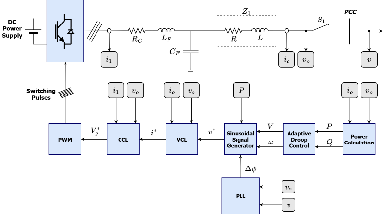
The MG control system block diagram for each DG is shown in Figure 1. The current measurement  is taken before the LC filter and transformed to the αβ reference frame (
 ,
,  ). Similarly, the current and voltage measurements (
 ,
,  ) after the LC filter are transformed to the
  reference frame (
 ,
,  ,
,  ,
,  ) to calculate active and reactive power (P and Q) through the power control loop. The droop control generates reference voltage amplitude and frequency using equations (1) and (2). The sinusoidal signal generator block produces the reference sinusoidal voltage
  , which is transformed to
  and
and  using (1) and (2). These voltages are then fed into the voltage control loop, which generates the reference current
  . This reference current is subsequently passed to the current control loop.
| 
| (1) |
| 
| (2) |
More details on the current and voltage control loops can be found in [50]. Finally, the voltage  is transformed back to the abc space to drive the DG inverter via pulse-width modulation generation (PWMG).
In equation (1) and equation (2), the gain  is used to accelerate the system's transient response to rapid changes in active power. The current control loop, along with a voltage control loop and an external power control loop, generates switching patterns to compensate for frequency deviation. The current control loop regulates the current flowing through the grid, while the voltage control loop keeps the voltage within the specified limits.
Figure 1. The block diagram of the MG control system for each DG
SYNCHRONIZATION OF DGS
It is important to note that the DG output voltage needs to be synchronized with the other DGs at the point of common coupling (PCC) before the DG is linked to it via the switch  . A phase-locked loop (PLL) block can be used to do this. Only when the converter is ready to connect to the microgrid, when switch is open and ready to be closed, the PLL is enabled. The PLL's main job is to synchronize the microgrid voltage (𝑣), sensed on the right side of the switch, with the converter's output voltage . As seen in Figure 2, the sinusoidal signal generator block receives the PLL's output (
 ). As seen in (1) and (2), this output is utilized to update the voltage
  phase. The cross-product of the input voltages must be forced to zero for the PLL to function. The stationary reference frame for the cross product of
  and may be expressed using the formula [51]:
| 
| (3) |
To eliminate the harmonics and noise present in the cross-product of sinusoidal AC signals, a discrete low-pass filter is utilized. Figure 2 illustrates typical PLL block diagram. Once synchronization is achieved through the PLL, the DG can be safely connected to the microgrid. Subsequently, the droop controller regulates frequency and power sharing, while the proposed CA-based adaptation mechanism continuously adjusts the droop coefficient to improve overall system performance. However, two factors are taken into consideration:
- It is decided that the cut-off frequency of the LPF will be one decade lower than the frequency of the microgrid. This will ensure a considerable reduction in the incidence of voltage harmonics.
- When selecting the PI gains, it is important to do so in a manner that can guarantee a rapid transient response from the PLL. Because the PLL can only function when the DG is detached from the load, no disturbances occur due to rapid fluctuations in its phase increment.
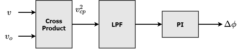
Figure 2. Typical PLL block diagram
CLASSICAL DROOP CONTROL METHOD
The main goals of the droop control method are the control of power sharing and the stabilization of voltage amplitude and frequency. The droop method is a popular method for primary control. Droop control is based on the behavior of synchronous generators in large power systems, where the frequency of the generator output decreases with an increase in load and vice versa. In a microgrid context, “droop” is the change of the DG output power according to the microgrid frequency or voltage. The active and reactive instantaneous powers are defined in the droop control loop as [52]:
| 
| (4) |
| 
| (5) |
Where , , , and are the DG’s voltage and current outputs in α and β coordinates. The active and reactive powers pass through a low-pass filter (LPF); thus, 𝑃 and 𝑄 can be evaluated from (6) and (7), where  is the cutoff frequency of the LPF.
| 
| (6) |
| 
| (7) |
The reference frequency  and amplitude voltage
  are calculated from the frequency droop coefficient (
 ) and the voltage droop coefficient (
 ) as [53]:
| 
| (8) |
| 
| (9) |
where  and
and  are the microgrid's nominal angular frequency and nominal voltage amplitude, respectively. Choosing the droop control parameters and in a microgrid depends on various factors, including the system dynamics and control objectives.
PROPOSED DROOP CONTROL METHOD
Because the active-power droop coefficient is mainly responsible for frequency regulation and sharing active power, the frequency deviation was chosen as the target for optimization. The voltage is kept at the right level by the inner voltage-control loop and the reactive-power droop controller. This section introduces the proposed primary control layer, a key contribution of this paper. This section has been divided into two sections: the first focuses on the CA principle, and the second addresses the adjustment flow chart for the droop gain .
Camel Algorithm Description
The CA is a nature-inspired optimization technique based on the behavior of camels traveling through deserts. In CA, the candidate solutions are camels looking for the best food source, while temperature, endurance, and visibility are used to balance exploration and exploitation. Besides, CA is used to adaptively tune the active-power droop coefficient () so that the frequency deviation of the islanded microgrid is minimized. The original mathematical formulation of CA, which is from [54], is adopted and changed here for the online droop-gain adjustment.
At the beginning of the caravan travel, we suppose that there are Nc camels spread out through the desert, looking randomly for the food supply as given below:
| 
| (10) |
where  is the camel location's minimal limit,
 is its maximum limit, d is the environment dimension, where
  , and Rand designates a random number uniformly distributed between 0 and 1. The location of the camel
  position at iteration (
 ) through the food searching area is represented by the vector
  . The temperature T of camel at the iteration iter is fluctuating between a minimum amount of temperature
  and a maximum amount of temperature
  as follows:
| 
| (11) |
The camel endurance  is affected by temperature changes as given below:
| 
| (12) |
Some camels may be unable to see the dunes, making it difficult for them to adjust their path to the grassed spot that a particular camel has discovered. As a result, there are two ways to update each camel's position. The update function is provided when the camel visibility v exceeds a particular visibility threshold ( ):
):
| 
| (13) |
where, according to a particular fitness function,  denotes the optimal location for all previous iterations (global best). represents the matrix of the PI controller parameters as follows:
| 
| (14) |
The frequency error’s absolute value serves as the fitness cost function,
| 
| (15) |
In this research, the algorithm was modified to depend on the error value and the sampling time ( ), rather than the number of iterations, thus enabling online optimization at each .
The waiting period of () is introduced to avoid excessive droop-gain updates at every simulation step and to allow the measured frequency error to reflect the effect of the previous control action. This small delay smooths the adaptive process without noticeably reducing the control bandwidth. The proposed algorithm performs as shown in Figure 3. The number of camels has been set to 20, D is 2, the visibility is 0.5, and  equals 0.2 rad/sec to provide a wide range for varying the value from 10~150 µrad/(W·s). It is worth mentioned, that the visibility is a random variable between 0 and 1 which is used for repeating the optimization process to get a better optimization variable:
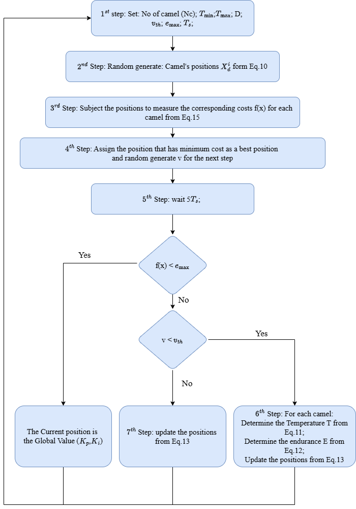
Figure 3. Flowchart of the Proposed CA
Despite the use of 20 camels, the online optimization problem remains one-dimensional since only the active-power droop coefficient () is being optimized by tuning the PI controller parameters ( ) In another words, the PI controller’s input is the frequency error, while the output is the droop coefficient. Thus, the computational effort is quite low as compared with that of multi-variable optimization problems. That is why the proposed approach can be easily run on standard DSPs or industrial microcontrollers. In an actual scenario, the adaptive layer could even run at a slower sampling rate of the supervisory level than the inner voltage and current loops.
Contrary to the original offline CA, the new approach can be considered an online adaptive tuner. Therefore, convergence is not considered a finite-iteration optimization problem but rather a continuous time minimization of the frequency deviation. The droop coefficient is limited by the specified lower and upper bounds, which stops unstable parameter updates. As the frequency error reduces, the adaptive changes in () are smaller, enabling the controller to stay around the value of the operation that results in the least frequency deviation. The Proposed algorithm training pseudocode is summarized as follows:
Algorithm 1. Pseudocode of the CA strategy |
1: Initialization: Set the parameters: Number of camels Nc, , , D, , and . 2: Initialize the location of each camel from Eq. (10). 3: Initial Evaluation: Subject the camel positions to measure the corresponding costs  for each camel from Eq. (15). Determine the current best position that has the minimum cost. Randomly generate a velocity (v) for the next step. for each camel from Eq. (15). Determine the current best position that has the minimum cost. Randomly generate a velocity (v) for the next step. 4: While (>): If v < then for = 1:Nc Compute the temperature T from Eq. (11) Compute the endurance E from Eq. (12) Update the camel positions from Eq. (13) End for Else for = 1: Nc Update the camel positions from Eq. (13) End for End If Subject the new positions to measure the corresponding costs from Eq. (15) Determine the position that has the minimum cost as the best position Randomly generate a new velocity (v) for the next step Wait for a duration of 5 End While 5: Output: The current position is the Global Value ( , ,  ) ) |
RESULTS AND DISCUSSION
This section presents the simulation results that validate the effectiveness of the proposed control strategy. The system consists of three DGs, line impedances, and a main load. The following subsections present the detailed simulation setup, the tests conducted, and a discussion of the results.
Simulation of the Proposed MG
The studied MG system for this simulation is shown in Figure 4. The used MG consists of three DGs, each equipped with a grid-forming converter programmed as a controller. Each converter includes a three-phase IGBT full-bridge power inverter and an LC filter. The impedances  ,
,  ,
,  ,
,  , and
, and  represent the impedances of the microgrid element of the transformers and transmission lines. The results are based on a discrete time-domain simulation with a sampling time of
  seconds. MATLAB/SIMULINK 2023a is used to execute the control strategies under the study. The parameters of the studied MG are presented in Table 1. The tested load is a balanced three-phase, using a constant power load with active power fluctuating between 5 kW and 10 kW.
Two simulation results were conducted to validate the proposed control approach. In the first test, constant droop gains are used. The results of this test are analyzed to compare a constant- system against the proposed adaptive- controller. Each test followed the same procedures with different 𝑚𝑝 gains: DG1 was soft-started at 𝑡=0 s, followed by the closing of switch 𝑆1 to connect DG1 of the PCC. At  s, DG2 was soft-started and connected via a switch
  as shown in Figure 4. Finally, DG3 was connected at
  s, completing the load-sharing process. Each DG connection (at
  s, s, and s) is considered. All DGs were programmed using the control parameters listed in Table 2.
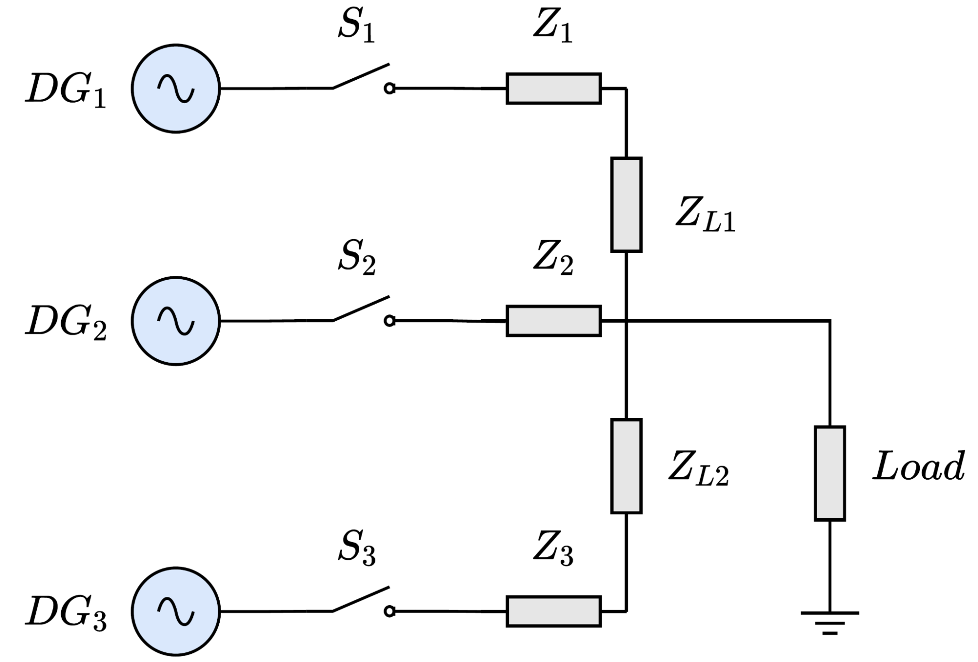
Figure 4. Proposed microgrid topology
Table 1. Specifications of the proposed microgrid
Parameter | Symbol | Value | Units |
Microgrid nominal power | S | 5 | KVA |
Inverter output inductors | L | 6 | mH |
Inverter output capacitors | C | 12 | μF |
DG1 Line impedance |
| 0.065+0.063j | Ω |
DG2 Line impedance 2 |
| 0.08+0.05j | Ω |
DG3 Line impedance 3 |
| 0.13+0.054j | Ω |
Bus Line impedance between DG1 and DG2 |
| 0.067+0.0075j | Ω |
Bus Line impedance between DG2 and DG3 |
| 0.078+0.0075j | Ω |
Main Load | Load | 5~10 | Kw |
Table 2. Proposed control parameters
Parameter | Symbol | Value | Units |
Microgrid nominal angular frequency | 
| 100π | Rad/Sec. |
Microgrid nominal Voltage | V | 
| V |
Power control loop cut off frequency |
| 2π | Rad/Sec. |
Sampling time | 
| 
| Sec. |
Current loop proportional factor | 
| 12 | V/A |
Voltage loop proportional factor | 
| 0.1 | A/V |
Testing Under Classical Method
To validate the proposed control strategy, the analysis and discussions of the trade-off between droop gain and system performance were conducted. In the first simulation, a constant droop gain of 200 µrad/(W·s) was employed. As illustrated in Figure 5, this configuration enables fast and precise power sharing with a maximum frequency deviation of 0.23 Hz. As will be shown in the next subsection, the proposed control strategy significantly reduces this error. In Figure 6, the droop gain was decreased to 50 µrad/(W·s), while this results in a lower maximum frequency error of 0.12 Hz, the slower response time compromises the power-sharing process, leading to an accumulated error. This outcome constant-𝑚𝑝e is undesirable and contradicts the anticipated behavior of the control strategy. The proposed control strategy aims to significantly reduce the maximum frequency error observed in the previous tests.
These tests illustrate that while choosing a large value results in fast response time and precise power sharing, it causes greater frequency deviations. On the other hand, a small value causes a slow response time at the expense of fewer frequency deviations. By dynamically adjusting the droop gain, the control system can achieve more balanced power sharing among the DGs while maintaining a lower frequency deviation. This approach leverages the trade-off between fast response and accurate power sharing, allowing the system to adapt to changing conditions and ensure stable operation. The suggested controller was able to deliver stable results when subjected to various scenarios of DG connection and load sharing conditions. Every time the adaptive droop method worked out a way to strike a compromise between rapid transient response and precise frequency regulation.
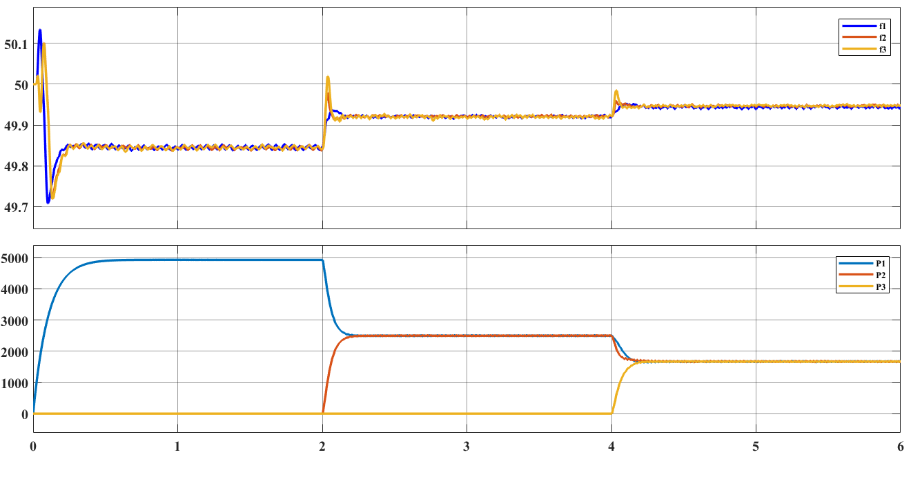
Figure 5. Frequency (top) and Active power (bottom) responses at =200 µrad/(W·s)
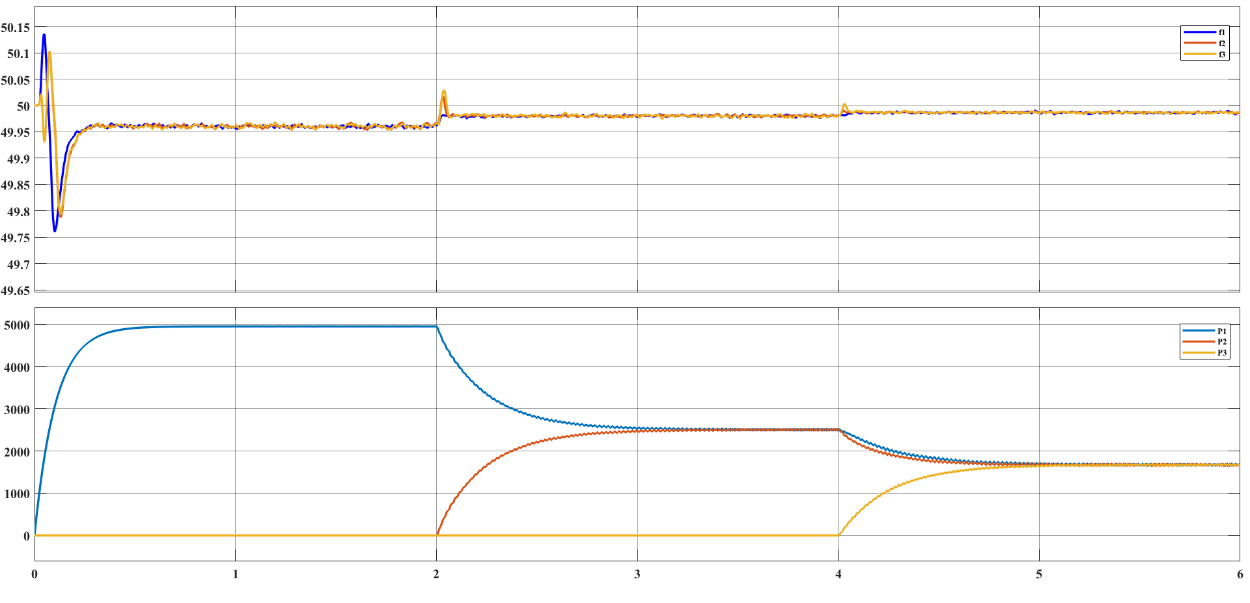
Figure 6. Frequency (top) and Active power (bottom) responses at =50 µrad/(W·s)
Testing with Proposed Control Strategy
Figure 7 illustrates the active power and frequency responses for a test using the proposed control strategy. The minimum and maximum values of the dynamic droop gain ( = 50 µrad/(W·s) and
  = 200 µrad/(W·s)) were selected based on the test results from the previous subsection with the constant droop gain. The results demonstrate accurate frequency recovery and a significant reduction in the maximum frequency deviation reaches to 0.05 Hz after less than 1 second. Notably, the system's response speed is sufficient to achieve precise power sharing during multi-event scenarios. By leveraging the trade-off between fast response and accurate power sharing, the proposed control strategy effectively minimizes the maximum frequency error. Note that, when the active power rate changes rapidly at , , and , the event is detected and, hence, the proposed controller adjusts 𝑚𝑝 towards its maximum to increase the power-sharing step response of the system. When the active power rate decreases toward zero, the controller reduces 𝑚𝑝 toward its minimum to restore the frequency. It can be seen that by dynamically adapting the droop gain, the proposed controller achieves a fast response with minimal steady-state error. As illustrated in Figure 7(D), the 𝑚𝑝 value is determined after the CA adjusts the parameters of the adaptive PI controller to generate the optimal control value.
The proposed Camel Algorithm-based adaptive strategy shows 60 ms (0.22 s vs 0.28 s) improvement in settling time over the fixed low-𝑚𝑝 setting (𝑚𝑝= 50). Although the improvement is small, it is of paramount practical significance for inverter-dominated autonomous microgrids. The lack of physical inertia inherent in such topologies results in a very high rate of change of frequency (ROCOF) during the first few milliseconds of a disturbance. Thus, the time period of transient electrical stress on the power electronic switches and energy storage systems is effectively reduced by about 21% in terms of frequency settling time. Most importantly, this rapid restoration prevents nuisance tripping of very sensitive under-frequency protection relays (UF) which normally operate on strict millisecond thresholds, thus avoiding unnecessary load shedding or possible cascading blackouts.
The adaptive behavior of the proposed controller can be seen for each DG connection event. When a sudden active-power mismatch occurs, the frequency deviation increases, and the CA reacts by increasing the droop coefficient toward its maximum limit. This action expedites the power reallocation among the DGs and diminishes the settling time. As the system approaches steady-state operation and the frequency deviation decreases, the droop coefficient gradually approaches its lower bound, so the frequency restoration accuracy is improved. Therefore, the adaptive mechanism always balances the transient performance and steady-state regulation as a function of the instantaneous operating condition of the microgrid.
Figure 7. Frequency response (A), Active power response (B), Active power change rate (C), and the response(D) with the proposed controller
Comparative Performance Analysis
The performance of the proposed adaptive control scheme is critically assessed against two static (fixed) configurations of the primary droop coefficient (): a high-inertia setting ( = 50 µrad/(W·s)) and a low-inertia setting ( = 200 µrad/(W·s)). This comparison is designed to empirically validate the necessity of the adaptive approach by demonstrating the fundamental trade-off limitations of static droop control. The results clearly demonstrate the limitations of fixed-droop operation effectiveness. Increasing the droop coefficient helps to share power better, but at the same time, it causes bigger frequency deviations, while decreasing the droop coefficient has the opposite effect on frequency deviation but results in worse transient performance. The CA-based adaptive controller presented in this paper changes the droop coefficient nonlinear in line with system operating conditions and successfully achieves a balance between these opposing objectives. Table 3 demonstrates that the proposed controller can provide the least frequency deviation but still retain a fast dynamic response across all operating events. Quantitative results in Table 3 clearly show that the CA-based adaptive controller performed very well. Certainly, these findings support the idea that the controller corrects the inherent trade-off between the speed of the transient response and steady-state frequency regulation, which is a feature of conventional droop control.
Table 3. The Comparison between the Proposed Control and the Traditional Control
At =200 µrad/(W·s) |
Time period (sec.) | Frequency response settling time (Sec.) | Power response settling time (Sec.) | Frequency range (Hz) |
0-2 | 0.41 | 0.67 | 49.73-49.85 |
2-4 | 0.22 | 0.21 | 49.85-49.92 |
4-6 | 0.15 | 0.25 | 49.92 ~49.95 |
At =50 µrad/(W·s) |
0-2 | 0.28 | 0.74 | 49.78-49.95 |
2-4 | 0.13 | 1.25 | 49.95-49.98 |
4-6 | 0.12 | 0.95 | 49.98-49.99 |
At Dynamic (from the Proposed Control) |
Time period (sec.) | Frequency response settling time (Sec.) | Power response settling time (Sec.) | Frequency range (Hz) |
0-2 | 0.22 | 0.68 | 49.95-50 |
2-4 | 0.18 | 0.3 | 49.95-50 |
4-6 | 0.15 | 0.4 | 49.95-50 |
Trade-Off of Fixed Droop Control
Table 3 confirms the inherent conflict in selecting a fixed value:
- -Low-inertia (200 µrad/ (W·s)) - Focus on Steady-State:
Steady-state performance: this value is effective at minimizing the frequency deviation, keeping the frequency within the tighter range of 49.73hz to 49.95 hz over the 0-2s period compared to the low setting.
Trans penalty: pursuing lower steady-state error (tighter range) comes at a high cost to the dynamic response. The high stiffness causes poor damping, resulting in oscillations and slower power response settling times (0.67s, 0-2s period). This configuration is unsuitable for systems requiring fast transient recovery.
- High inertia (50 µrad/ (W·s)) - Focus on Transient Stability:
Transient Benefit: The low droop gain provides better damping and faster frequency settling times (0.28s, 0-2s period), indicating superior transient stability immediately following a load disturbance.
Steady-State Penalty: This is achieved at the expense of a severely widened frequency band. The frequency operates within a broader, less stable range (e.g., 49.78 Hz to 49.95 Hz) during 0-2s and, critically, fails to achieve frequency restoration as effectively as the high setting. This configuration is prone to cumulative frequency drift.
The analysis clearly establishes that no single static value can simultaneously satisfy both the transient stability requirement (fast, low-oscillation response) and the minimum steady-state frequency deviation requirement. This limitation mandates the development of an adaptive mechanism.
Superiority of the proposed dynamic control
The third configuration, which uses the Dynamic tuned adaptively by the Camel Algorithm (CA), is designed to navigate this trade-off by adjusting the droop coefficient in real time based on the system state.
- Optimized Transient Response: The Dynamic approach achieves the best possible frequency settling time (0.22s, 0-2s period) among all three configurations. Crucially, it maintains this speed while keeping the frequency within the tightest range (49.95 Hz to 50 Hz), demonstrating superior damping and minimal transient overshoot.
- Minimized Frequency Deviation: Unlike the two static settings, the Dynamic consistently forces the frequency into the narrowest, most stable band (49.95 Hz to 50 Hz) across all load conditions. This significant reduction in frequency deviation relative to the static cases (=50 and =200) confirms the effectiveness of the CA in finding near-optimal parameter adjustments that stabilize the system near its nominal value.
- Enhanced Power Response: The power response settling time for the Dynamic is consistently faster or comparable to the best static performance, particularly for the critical load changes (0.3s at 2-4s, and 0.4s at 4-6s). This validates that the adaptive mechanism enhances frequency stability without compromising the accuracy or speed of active power sharing.
In summary, when compared to previous classical droop-control methods, the CA-based controller offered here features a straightforward online optimization scheme with very minimal computational effort. Whereas conventional fixed-gain strategies remain unchanged throughout operation, the approach modifies the droop coefficient progressively based on the microgrid operating condition. The results achieved show enhanced frequency regulation and active power-sharing abilities along with keeping the implementation structure simple.
CONCLUSIONS
The present study presents a new control scheme that will bring about an enhancement in frequency regulation and a decrease in the time of the transient phase corresponding to the sharing of active power. However, the CA-based adaptive controller presented here is the one that outperformed all other techniques because it changed the droop coefficient in an online manner. This controller reduced the time required for frequency stabilization to approximately 0.22 seconds. Additionally, during all the operating events, the microgrid frequency was kept within a very small range of 49.95 and 50 Hz. Also, the reaction of sharing electrical power was kept active with settling times of between 0.30 s and 0.40 s during the next DG connections, which are a positive demonstration of the ability to strike a balance between transient performance and steady-state accuracy. The results obtained clearly indicate that the proposed adaptive droop-control method is a very efficient technique computationally for the primary control of the islanded microgrids since, online, only a single parameter of control is being optimized. Thus, the proposed controller enhances frequency stability and power-sharing accuracy without the increase of control complexity. However, it is important to note that our study relies solely on simulation and employs a centralized communication architecture. Hence, future work will be dedicated to implement experiments, real-time hardware validation, communication-delay analysis, comparison with other adaptive optimization algorithms, and the extension of the adaptive tuning concept to reactive-power droop control.
ABBREVIATIONS
The following abbreviations are used in this manuscript.
Microgrid | : | MG |
DER | : | Distributed Energy Sources |
RER | : | Renewable Energy Sources |
DG | : | Distributed Generators |
CA | : | Camel Algorithm |
PLL | : | Phase Locked Loop |
PI | : | Proportional and Integral |
REFERENCES
- Z. Wanpeng, Y. Libin, L. Zhengxi, W. Kai, Z. Weiwen, and L. Qianjie, “Optimization Method for Multi Energy Microgrid Operation Considering Carbon Emissions,” 2024 IEEE 8th Conference on Energy Internet and Energy System Integration (EI2), pp. 5093–5098, Nov. 2024, https://doi.org/10.1109/ei264398.2024.10990821.
- G. T. Chala and S. M. Al Alshaikh, “Solar Photovoltaic Energy as a Promising Enhanced Share of Clean Energy Sources in the Future—A Comprehensive Review,” Energies, vol. 16, no. 24, p. 7919, Dec. 2023, https://doi.org/10.3390/en16247919.
- W. Zhang, T. Qian, X. Chen, K. Huang, W. Tang, and Q. Wu, “Resilient Economic Control for Distributed Microgrids Under False Data Injection Attacks,” IEEE Transactions on Smart Grid, vol. 12, no. 5, pp. 4435–4446, Sep. 2021, https://doi.org/10.1109/tsg.2021.3073874.
- C. Lyu, Y. Jia, and Z. Xu, “A Novel Communication-Less Approach to Economic Dispatch for Microgrids,” IEEE Transactions on Smart Grid, vol. 12, no. 1, pp. 901–904, Jan. 2021, https://doi.org/10.1109/tsg.2020.3018622.
- M. Hu, Y. Wang, B. Xia, and G. Huang, “What is the relationship between energy consumption and economic development? New evidence from a rapidly growing economic development region,” Environment, Development and Sustainability, vol. 25, no. 4, pp. 3601–3626, Apr. 2022, https://doi.org/10.1007/s10668-022-02196-8.
- J. Huo and C. Peng, “Depletion of natural resources and environmental quality: Prospects of energy use, energy imports, and economic growth hindrances,” Resources Policy, vol. 86, p. 104049, Oct. 2023, https://doi.org/10.1016/j.resourpol.2023.104049.
- S. J. Yaqoob et al., “Efficient Flatness Based Energy Management Strategy for Hybrid Supercapacitor/Lithium-ion Battery Power System,” IEEE Access, vol. 10, pp. 132153–132163, 2022, https://doi.org/10.1109/access.2022.3230333.
- F. A. Abbas, A. A. Obed, M. A. Qasim, S. J. Yaqoob, and S. Ferahtia, “An efficient energy-management strategy for a DC microgrid powered by a photovoltaic/fuel cell/battery/supercapacitor,” Clean Energy, vol. 6, no. 6, pp. 827–839, Dec. 2022, https://doi.org/10.1093/ce/zkac063.
- S. M. Rostami and M. Hamzeh, “An Adaptive Multi-Functional Control Strategy for Power Management and Voltage-Frequency Regulation of PV, BESS, and Hybrid Units in a Microgrid,” IEEE Transactions on Smart Grid, vol. 15, no. 4, pp. 3446–3458, Jul. 2024, https://doi.org/10.1109/tsg.2023.3345741.
- T. Kaewnukultorn, S. B. Sepúlveda-Mora, and S. Hegedus, “The impacts of DC/AC ratio, battery dispatch, and degradation on financial evaluation of bifacial PV+BESS systems,” Renewable Energy, vol. 236, p. 121402, Dec. 2024, https://doi.org/10.1016/j.renene.2024.121402.
- M. Cavus, A. Allahham, K. Adhikari, and D. Giaouris, “A Hybrid Method Based on Logic Control and Model Predictive Control for Synthesizing Controller for Flexible Hybrid Microgrid with Plug-and-Play Capabilities,” Available at SSRN 4473008, 2023, https://doi.org/10.2139/ssrn.4473008.
- B. Aljafari, S. Vasantharaj, V. Indragandhi, and R. Vaibhav, “Optimization of DC, AC, and Hybrid AC/DC Microgrid-Based IoT Systems: A Review,” Energies, vol. 15, no. 18, p. 6813, Sep. 2022, https://doi.org/10.3390/en15186813.
- M. B. Abdelghany, A. Al-Durra, H. H. Zeineldin, and F. Gao, “A Coordinated Multitimescale Model Predictive Control for Output Power Smoothing in Hybrid Microgrid Incorporating Hydrogen Energy Storage,” IEEE Transactions on Industrial Informatics, vol. 20, no. 9, pp. 10987–11001, Sep. 2024, https://doi.org/10.1109/tii.2024.3396343.
- N. Khosravi, “A hybrid control approach to improve power quality in microgrid systems,” Artificial Intelligence Review, vol. 58, no. 10, Jul. 2025, https://doi.org/10.1007/s10462-025-11300-z.
- N. Alamir, S. Kamel, T. F. Megahed, M. Hori, and S. M. Abdelkader, “Developing Hybrid Demand Response Technique for Energy Management in Microgrid Based on Pelican Optimization Algorithm,” Electric Power Systems Research, vol. 214, p. 108905, Jan. 2023, https://doi.org/10.1016/j.epsr.2022.108905.
- G. Shahgholian, M. Moradian, and A. Fathollahi, “Droop control strategy in inverter‐based microgrids: A brief review on analysis and application in islanded mode of operation,” IET Renewable Power Generation, vol. 19, no. 1, Jan. 2025, https://doi.org/10.1049/rpg2.13186.
- D. Ioris, P. T. de Godoy, K. D. R. Felisberto, P. Poloni, A. B. de Almeida, and D. Marujo, “Microgrid Operation and Control: From Grid-Connected to Islanded Mode,” Planning and Operation of Active Distribution Networks, pp. 233–256, 2022, https://doi.org/10.1007/978-3-030-90812-6_9.
- G. K. Taneja, G. Modi, B. Singh, A. Verma, and V. Narayanan, “An Improved Control Strategy to Reduce Operating Hours of DG Genset in Solar PV-BES-DG Based AC Microgrid,” IEEE Transactions on Industry Applications, vol. 59, no. 3, pp. 3713–3726, May 2023, https://doi.org/10.1109/tia.2023.3246464.
- J.-W. Chang, J.-Y. Park, and P.-I. Hwang, “Decentralized Secondary Control of DGs for an Islanded Hybrid AC/DC Microgrid,” IEEE Access, vol. 12, pp. 3597–3610, 2024, https://doi.org/10.1109/access.2023.3344075.
- O. E. Egbomwan, S. Liu, and H. Chaoui, “Twin Delayed Deep Deterministic Policy Gradient (TD3) Based Virtual Inertia Control for Inverter-Interfacing DGs in Microgrids,” IEEE Systems Journal, vol. 17, no. 2, pp. 2122–2132, Jun. 2023, https://doi.org/10.1109/jsyst.2022.3222262.
- J. Zhang, B. Sun, and D. Zhao, “A Novel Event-Triggered Secondary Control Strategy for Distributed Generalized Droop Control in Microgrid Considering Time Delay,” IEEE Transactions on Power Electronics, vol. 38, no. 5, pp. 5963–5978, May 2023, https://doi.org/10.1109/tpel.2023.3241063.
- A. Kumar et al., “An effective energy management system for intensified grid-connected microgrids,” Energy Strategy Reviews, vol. 50, p. 101222, Nov. 2023, https://doi.org/10.1016/j.esr.2023.101222.
- M. Mannan, M. Mansor, M. S. Reza, M. F. Roslan, P. J. Ker, and M. A. Hannan, “Recent Development of Grid-Connected Microgrid Scheduling Controllers for Sustainable Energy: A Bibliometric Analysis and Future Directions,” IEEE Access, vol. 12, pp. 90606–90628, 2024, https://doi.org/10.1109/access.2024.3419443.
- M. Hajiaghapour-Moghimi, E. Hajipour, K. Azimi Hosseini, M. Vakilian, and M. Lehtonen, “Cryptocurrency mining as a novel virtual energy storage system in islanded and grid-connected microgrids,” International Journal of Electrical Power & Energy Systems, vol. 158, p. 109915, Jul. 2024, https://doi.org/10.1016/j.ijepes.2024.109915.
- M. Y. A. Khan, H. Liu, Z. Yang, J. Wang, and Y. Zhang, “Hierarchical control of microgrid: a comprehensive study,” Electrical Engineering, vol. 107, no. 10, pp. 13681–13712, Jun. 2025, https://doi.org/10.1007/s00202-025-03230-4.
- R. Trivedi and S. Khadem, “Implementation of artificial intelligence techniques in microgrid control environment: Current progress and future scopes,” Energy and AI, vol. 8, p. 100147, May 2022, https://doi.org/10.1016/j.egyai.2022.100147.
- K. E. Ojo, A. K. Saha, and V. M. Srivastava, “Review of Advances in Renewable Energy-Based Microgrid Systems: Control Strategies, Emerging Trends, and Future Possibilities,” Energies, vol. 18, no. 14, p. 3704, Jul. 2025, https://doi.org/10.3390/en18143704.
- S. H. H. Dolatabadi, A. Soleimani, A. Ebtia, and M. Shafie-khah, “Enhancing Voltage Profile in Islanded Microgrids Through Hierarchical Control Strategies,” lectric Power Systems Research, vol. 231, p. 110270, 2023, https://doi.org/10.2139/ssrn.4653283.
- S. Li, A. Oshnoei, F. Blaabjerg, and A. Anvari-Moghaddam, “Hierarchical Control for Microgrids: A Survey on Classical and Machine Learning-Based Methods,” Sustainability, vol. 15, no. 11, p. 8952, Jun. 2023, https://doi.org/10.3390/su15118952.
- G. Ahmad, A. Hassan, A. Islam, M. Shafiullah, M. A. Abido, and M. Al-Dhaifallah, “Distributed Control Strategies for Microgrids: A Critical Review of Technologies and Challenges,” IEEE Access, vol. 13, pp. 60702–60719, 2025, https://doi.org/10.1109/access.2025.3552940.
- F. Nawaz, E. Pashajavid, Y. Fan, and M. Batool, “A Comprehensive Review of the State-of-the-Art of Secondary Control Strategies for Microgrids,” IEEE Access, vol. 11, pp. 102444–102459, 2023, https://doi.org/10.1109/access.2023.3316016.
- T. Yang, J. Lai, C. Yu, X. Wang, and Q. Xiao, “Distributed Two-Layer Predictive Control of AC Microgrid Clusters With Communication Delays,” IEEE Transactions on Smart Grid, vol. 16, no. 3, pp. 2040–2051, May 2025, https://doi.org/10.1109/tsg.2025.3539789.
- A. Osama, T. H. M. EL-Fouly, H. H. Zeineldin, and E. F. El-Saadany, “A data-driven droop control strategy for reactive power sharing and stability enhancement in islanded AC microgrids,” International Journal of Electrical Power & Energy Systems, vol. 176, p. 111736, Mar. 2026, https://doi.org/10.1016/j.ijepes.2026.111736.
- A. Solat, G. B. Gharehpetian, M. S. Naderi, and A. Anvari-Moghaddam, “A novel consensus-based control method for SoC balancing of distributed energy storage systems in isolated AC microgrids,” International Journal of Electrical Power & Energy Systems, vol. 176, p. 111692, Mar. 2026, https://doi.org/10.1016/j.ijepes.2026.111692.
- A. Shamkhi and B. H. Jasim, “Local Frequency Restoration-Based Communication-Free Approach in Islanded Microgrids,” Iraqi Journal for Electrical and Electronic Engineering, vol. 22, no. 1, pp. 435–449, Jun. 2026, https://doi.org/10.37917/ijeee.22.1.38.
- H. Liang, B. Li, X. Jiang, and S. Xu, “Distributed Predefined-Time Control for Islanded AC Microgrid Under FDI Attacks,” IEEE Transactions on Industrial Informatics, pp. 1–9, 2026, https://doi.org/10.1109/tii.2026.3693673.
- Y. Yang, P. Yang, W. Lin, Z. Li, and G. Lu, “A decentralized control for Non-error frequency regulation in an islanded microgrid containing multiple VSGs,” International Journal of Electrical Power & Energy Systems, vol. 133, p. 107337, Dec. 2021, https://doi.org/10.1016/j.ijepes.2021.107337.
- Y. Jiang, Y. Yang, S.-C. Tan, and S.-Y. R. Hui, “Distribution Power Loss Mitigation of Parallel-Connected Distributed Energy Resources in Low-Voltage DC Microgrids Using a Lagrange Multiplier-Based Adaptive Droop Control,” IEEE Transactions on Power Electronics, vol. 36, no. 8, pp. 9105–9118, Aug. 2021, https://doi.org/10.1109/tpel.2021.3050506.
- J. Mohammadi and F. Badrkhani Ajaei, “Improved Mode-Adaptive Droop Control Strategy for the DC Microgrid,” IEEE Access, vol. 7, pp. 86421–86435, 2019, https://doi.org/10.1109/access.2019.2924994.
- C. Liu and S. Sun, “Event-triggered optimal and suboptimal distributed Kalman consensus filters for sensor networks,” Journal of the Franklin Institute, vol. 358, no. 9, pp. 5163–5183, Jun. 2021, https://doi.org/10.1016/j.jfranklin.2021.04.033.
- J. M. Rey, P. P. Vergara, M. Castilla, A. Camacho, and J. Miret, “Local hierarchical control for industrial microgrids with improved frequency regulation,” 2018 IEEE International Conference on Industrial Technology (ICIT), pp. 1019–1024, Feb. 2018, https://doi.org/10.1109/icit.2018.8352318.
- D. Y. Yamashita, I. Vechiu, and J.-P. Gaubert, “A review of hierarchical control for building microgrids,” Renewable and Sustainable Energy Reviews, vol. 118, p. 109523, Feb. 2020, https://doi.org/10.1016/j.rser.2019.109523.
- M. A. Hassan and M. A. Abido, “Optimal Design of Microgrids in Autonomous and Grid-Connected Modes Using Particle Swarm Optimization,” IEEE Transactions on Power Electronics, vol. 26, no. 3, pp. 755–769, Mar. 2011, https://doi.org/10.1109/tpel.2010.2100101.
- J. M. Rey, P. Marti, M. Velasco, J. Miret, and M. Castilla, “Secondary Switched Control With no Communications for Islanded Microgrids,” IEEE Transactions on Industrial Electronics, vol. 64, no. 11, pp. 8534–8545, Nov. 2017, https://doi.org/10.1109/tie.2017.2703669.
- A. Bidram and A. Davoudi, “Hierarchical Structure of Microgrids Control System,” IEEE Transactions on Smart Grid, vol. 3, no. 4, pp. 1963–1976, Dec. 2012, https://doi.org/10.1109/tsg.2012.2197425.
- T.-T. Nguyen, H.-J. Yoo, and H.-M. Kim, “A Droop Frequency Control for Maintaining Different Frequency Qualities in a Stand-Alone Multimicrogrid System,” IEEE Transactions on Sustainable Energy, vol. 9, no. 2, pp. 599–609, Apr. 2018, https://doi.org/10.1109/tste.2017.2749438.
- N. Sajeev, S. Arinze Obi, and J.-J. Jung, “Optimized Distributed Control for Power Sharing and Voltage-Frequency Regulation in Islanded Microgrids,” IEEE Access, vol. 13, pp. 121616–121629, 2025, https://doi.org/10.1109/access.2025.3586743.
- N. M. Dehkordi and V. Nekoukar, “Adaptive distributed stochastic deep reinforcement learning control for voltage and frequency restoration in islanded AC microgrids with communication noise and delay,” Scientific Reports, vol. 15, no. 1, Jul. 2025, https://doi.org/10.1038/s41598-025-13010-6.
- A. Shamkhi, B. H. Jasim, B. N. Alhasnawi, A. M. Jasim, V. Soběslav, and V. Bureš, “A centralized control architecture of a hybrid photovoltaic, wind turbine, and battery autonomous microgrid with a support diesel generator,” Energy Conversion and Management: X, vol. 28, p. 101387, Oct. 2025, https://doi.org/10.1016/j.ecmx.2025.101387.
- A. C. Zambroni de Souza and M. Castilla, Eds., Microgrids design and implementation. New York, NY, USA: Springer International Publishing, 2019. https://doi.org/10.1007/978-3-319-98687-6.
- A. Bidram and A. Davoudi, “Hierarchical Structure of Microgrids Control System,” IEEE Transactions on Smart Grid, vol. 3, no. 4, pp. 1963–1976, Dec. 2012, https://doi.org/10.1109/tsg.2012.2197425.
- N. J. Aklo and M. T. Rashid, “Correction to: Mitigation of take-or-pay concept drawbacks in hybrid microgrid,” Electrical Engineering, vol. 105, no. 1, pp. 77–77, Nov. 2022, https://doi.org/10.1007/s00202-022-01682-6.
- J. M. Guerrero, M. Chandorkar, T.-L. Lee, and P. C. Loh, “Advanced Control Architectures for Intelligent Microgrids—Part I: Decentralized and Hierarchical Control,” IEEE Transactions on Industrial Electronics, vol. 60, no. 4, pp. 1254–1262, Apr. 2013, https://doi.org/10.1109/tie.2012.2194969.
- R. S. Ali, F. M. Alnahwi, and A. S. Abdullah, “A modified camel travelling behaviour algorithm for engineering applications,” Australian Journal of Electrical and Electronics Engineering, vol. 16, no. 3, pp. 176–186, Jul. 2019, https://doi.org/10.1080/1448837x.2019.1640010.
Haider H. Ali (An Adaptive Droop Control Strategy for Frequency Restoration in an AC Islanded Microgrid)