ISSN: 2685-9572 Buletin Ilmiah Sarjana Teknik Elektro
Vol. 8, No. 4, August 2026, pp. 1127-1147
Adaptive Smart Energy Management for Wind-Battery Systems Considering Grid Fault Scenarios
Habib Chaib 1, Housseyn Chaib 2, Belkacem Belabbas 1, Fajer M. Alelaj 2, Alfian Ma’arif 3,
Mohamed Metwally Mahmoud 4,5,6, Vojtech Blazek 6, Shady M. Sadek 7
1 Department of Electrical Engineering, Laboratory of Electrical Engineering and Plasmas, University Ibn Khaldoun, Tiaret, Algeria
2 Water Research Center, Kuwait Institute for Scientific Research, Kuwait
3 Department of Electrical Engineering, Universitas Ahmad Dahlan, Yogyakarta, Indonesia,
4 Electrical Engineering Department, Faculty of Energy Engineering, Aswan University, Aswan 81528, Egypt
5 Jadara University Research Center, Jadara University, P.O Box 733, Irbid, Jordan
6 ENET Centre, CEET, VSB—Technical University of Ostrava, Ostrava, 708 00, Czech Republic
7 Electrical Power and Machines Engineering Department, Faculty of Engineering, International Academy for Engineering and Media Science, Cairo, Egypt
ARTICLE INFORMATION |
| ABSTRACT |
Article History: Received 27 February 2026 Revised 04 June 2026 Accepted 11 August 2026 |
| 
This work introduces a novel energy management system based on radial basis function neural network (RBFNN) adapted for both grid-connected and segmented modes. The system components are electrical distribution grid, wind generator, power electronic converters and batteries. The study uses intelligent control and prevents the spread of potential problems or disturbances. This system incorporates various controllers responsible of specific functions like MPP monitoring, of battery charging and discharging, and of an inverter for effectively managing the transition between energy sources based on load requirements and available sources operating at their MPP. The objectives are to facilitate coordinated operation among distributed energy resources, ensuring the provision of necessary active power and additional services as necessary. The simulation uses MATLAB/Simulink environment. Simulation results demonstrate the effectiveness and feasibility of the proposed strategy. Overall, the obtained results affirm the practicality and advantages of employing neural networks in energy management systems. |
Keywords: Maximum Power Point; Wind Generator; Battery Storage; Grid-Connected & Stand-Alone Modes; Energy Management; Radial Basis Function Neural Network |
Corresponding Author: Mohamed Metwally Mahmoud, Electrical Engineering Department, Faculty of Energy Engineering, Aswan University, Aswan 81528, Egypt. Email: metwally_m@aswu.edu.eg |
This work is open access under a Creative Commons Attribution-Share Alike 4.0 
|
Document Citation: H. Chaib, H. Chaib, B. Belabbas, F. M. Alelaj, A. Ma'arif, M. M. Mahmoud, V. Blazek, and S. M. Sadek, "Adaptive Smart Energy Management for Wind-Battery Systems Considering Grid Fault Scenarios," Buletin Ilmiah Sarjana Teknik Elektro, vol. 8, no. 4, pp. 1127-1147, 2026, DOI: 10.12928/biste.v8i4.16033. |
INTRODUCTION
Despite challenges such as supply chain disruptions, shipping delays, and price increases for components used in wind and solar energy production, the capacity for renewable power saw a remarkable 17% growth in 2021, reaching an unprecedented high of over 314 GW of added capacity. The total installed renewable power capacity also surged by 11%, reaching approximately 3,146 GW [1]–[3]. However, this growth falls short of the necessary deployment required to align the world with the target of achieving net-zero emissions by 2050. Renewables continued to dominate the share of newly installed capacity, reaching a record-breaking 84% of total new installations. Despite this growth, renewables accounted for 28.3% of global electricity generation in 2021, similar to 2020 levels (28.5%), marking an increase from 20.4% in 2011 [4][5].
However, MGs represent small-scale electrical grids comprising DERs like ESSs, distributed generation systems, and controllable/non-controllable loads [6][7]. To manage these diverse technologies effectively, a robust management system is necessary, ensuring reliability, effective cost, and efficient operations. Advancements in digital technologies, including microprocessor systems and power electronics, have enabled the development of various applications in the smart grid, particularly in controller and energy converter advancements [8][9].
Recent research contributions have significantly affected areas like data acquisition, automation, and control within MG systems [10][11]. MGs not only integrate distributed generation into the utility grid in a reliable and environmentally friendly manner but also exhibit high resilience against natural phenomena and active distribution grids. Consequently, we have reduced energy losses during transmission and distribution, as well as decreased construction time and investment requirements [12][13].
The paper presents a novel EMC scheme tailored for a wind energy-battery storage system, based on RBFNN, designed to operate flexibly in both grid-connected and standalone modes [14][15]. Unlike conventional methods that use separate controllers for each operational mode, this system employs a unified controller for streamlined operation. This system integrates a battery source intended as a backup unit, capable of supplying power during emergencies to critical loads and ensuring voltage and frequency stability in the local load [16]. Moreover, it enables the system to provide power to a local load and establish a connection to the grid as needed. Positioning the battery in parallel with the wind system allows it to either absorb or inject real power via a converter [17][18]. The converter's mode of operation adjusts to various scenarios: functioning in boost mode when the battery supplies power to a grid or load, and switching to buck mode when the battery draws power from the wind conversion system. This bidirectional capacity enables the battery to both contribute to and receive power from the system, as required by the circumstances. Moreover, in scenarios where issues arise within the grid, such as voltage or frequency fluctuations, the system ensures grid isolation to maintain overall system integrity [19][20]. In such instances, a control center intervenes to regulate frequency and voltage levels to align with the load requirements, ensuring the continuous and stable supply of power to consumers [21]. This adaptive and responsive control mechanism is vital in maintaining system reliability and meeting consumer demand, especially during grid disturbances or irregularities.
The study highlights the potential of the proposed EMS model for enhancing EM, cost efficiency, and environmental sustainability in hybrid MGs [22]. The system's control unit manages energy distribution among the grid, batteries, and load, optimizing performance in all modes. This results in a more efficient and reliable energy system [23]. The study highlights the feasibility and efficiency of integrating green hydrogen into hybrid energy systems for both grid-connected and autonomous applications [24]. The study demonstrates that hybrid PV systems are a viable, sustainable, and economically beneficial option for energy generation, supporting the transition to a more resilient and sustainable energy matrix [25]. The proposed system demonstrates a robust and cost-efficient approach to managing DC MGs, integrating diverse energy sources and leveraging predictive optimization to meet dynamic energy demands [26]. The proposed intelligent EMS significantly improves EM, cost reduction, and operational efficiency in MGs [27][28].
The contribution of this work is centered on the following terms. Extracting the maximum energy from the WT using MPPT when operating in two autonomous modes, and is integrated with the grid. This work proposes a neural network-based EMS to monitor and control energy sources, manage the DC bus, and regulate battery charging and discharging. It includes calculating the energy supply when there is insufficient availability to meet demand and directing any excess to either the battery or the power grid. Disconnecting the grid in the event of a fault to protect each component of the system.
The remainder of this paper is organized as follows. The modeling of the different subsystems in terms of equations is first presented. Next, the proposed fuzzy algorithms used for MPPT are introduced. Then, the fuzzy management strategies are described. After that, the simulation results are presented and analyzed. Finally, the paper concludes with the main findings and future perspectives.
SYSTEM DESCRIPTION, MODELLING
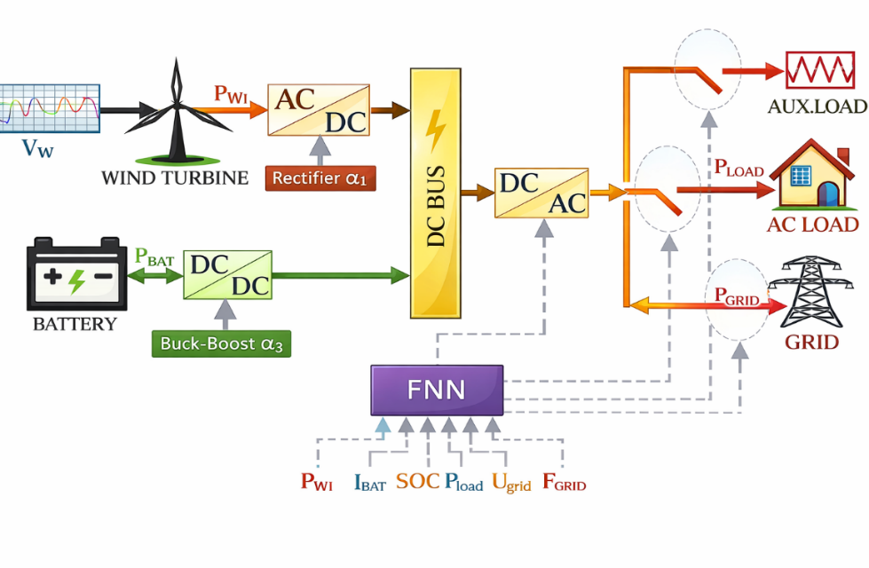
Figure 1 illustrates the WECS, which comprises a PMSG powered by a wind turbine. The system comprises a generator-side AC/DC converter, a grid-side DC/AC converter, and a battery storage unit connected to the DC link via a bi-directional buck-boost DC/DC converter. This configuration allows the system to supply a local load and link to a grid.
- Hybrid power system
Wind System Model
The wind-derived mechanical energy is detailed as follows [29], [30]
| 
| (1) |
where  is the power extracted from the wind;
  is the density of the air (
 );
);  is the radius of the blade (
 );
);  is the speed of the wind (
 ); and
  (
( ) represents the power coefficient, where
  denotes the tip speed ratio. The definition of the parameter is as follows
| 
| (2) |
The pitch angle  is maintained constant during MPPT control (
 ),
),  represents the mechanical speed of the turbine. The input torque for the turbine is derived from [31]:
| 
| (3) |
The generator is modelled by the following voltage equations in dq-axes [32]:
| 
| (4) |
| 
| (5) |
where  and
and  represent the currents in the (
 ) reference frame;
  stands for the stator resistance,
  denotes the electrical rotation speed; and
  along with
  indicate the stator flux linkages along the
  and
and  -axes are acquired through:
| 
| (6) |
| 
| (7) |
where  and
and  represent the on-axis inductances in the () reference frame, and
  stands for the rotor magnetic flux generated by the generator.
The electromagnetic torque expression  is given by [33]:
| 
| (8) |
wherein, P signifies the count of pole pairs.
The mechanical equation connecting the generator and wind turbine is described by [34]:
| 
| (9) |
where  denotes the torque exerted by the turbine on the generator,
  stands for the equivalent moment of inertia, and
  represents the viscous damping coefficient.
Storage Modeling
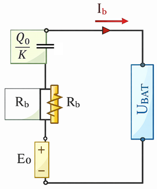
It is based on the electrical diagram shown in Figure 2, containing three elements: a voltage source, the internal resistance, and the capacitor [35]–[37].
| 
| (10) |
where  is the open circuit voltage of the battery, V;
  is a battery-dependent constant;
  is the internal battery resistance, Ω;
  is the discharging current, A;
  indicates the battery discharge status; and
  is the battery capacity in (Ah).
- Electrical model of the battery
Grid Model
The dynamic grid connection model, employing a reference frame that synchronously rotates with the grid voltage space vector, is depicted as follows [38]–[41]
| 
| (11) |
| 
| (12) |
where  represents the resistance and
  signifies the inductance of the filter, with the latter positioned between the converter and the grid,
  and
and  denote the inverter voltage components, while
  stands for the electrical angular velocity of the grid.
MSC Regulation and Control
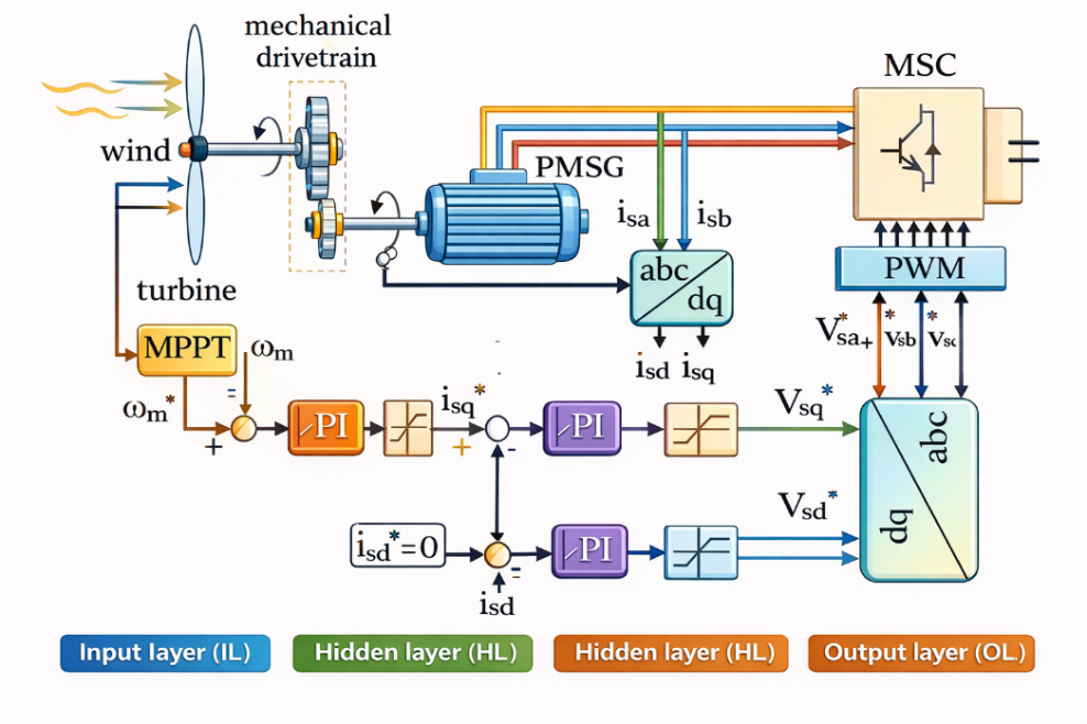
To regulate the PMSG under variable wind velocity conditions, the MPPT algorithm is utilized [42]–[44]. This algorithm ensures that the PMSG operates at the optimal speed corresponding to the MPP when the wind speed is below the nominal value, as illustrated in Figure 3.
- Diagram of the proposed control system of the MSC
The mathematical model of the control of the mechanical speed of PMSG performed by the PI controller is given by the following relationship [45]–[47]:
| 
| (13) |
where  is the reference speed given by MPPT; is the speed of measured PMSG;
  is the proportional gain; and
  is the integral gain.
POWER MANAGEMENT CONTROL
The control strategy for the hybrid energy system should be able to satisfy load requirements under different weather conditions, while at the same time optimizing energy flow to coordinate numerous energy sources synchronously, as shown in Figure 1. This subheading is concerned with the derivation of the nonlinear control law used to regulate energy exchange among the battery, load, and the grid [48][49].
This subject also involves DC-link voltage control, which is critical in the system's overall stability and performance. The control strategy in question is based on the input/output feedback linearization technique. Unlike conventional approaches where the GSC controls the DC-link voltage, the current strategy gives that function to the bi-directional buck-boost converter.
The selection provides greater flexibility in energy routing; particularly beneficial during grid fault conditions. In order to improve system robustness, the strategy includes a grid fault management function to enable dynamic reconfiguration of the system operating mode. In case of a grid failure or instability, the system would automatically transition to islanded mode, with power being supplied only from local sources such as the battery and renewable generators. When the grid is stable and support is needed from it to supply the load demand, the controller would automatically transition back to grid-connected mode, resynchronizing with the utility.
This intelligent mode-switching functionality ensures a fault-tolerant and continuous power supply, significantly enhancing the hybrid system's robustness. The dynamic behavior of the buck-boost converter is derived from the power balance equation of the back-to-back converter system, expressed by the following equation
| 
| (14) |
where  is the power at the DC-link;
  is the generator-side converter's output power;
  is the power of charge (positive for discharge, negative for charge);
  represents the power demand of the load;
  is the power injected into or withdrawn from the grid; and
  denotes the DC-link capacitor, and the dynamics of its voltage can be modeled by
| 
| (15) |
This control structure is graphically represented in the flowchart shown in Figure 4, which outlines the power management algorithm of the hybrid system for different grid and load conditions.
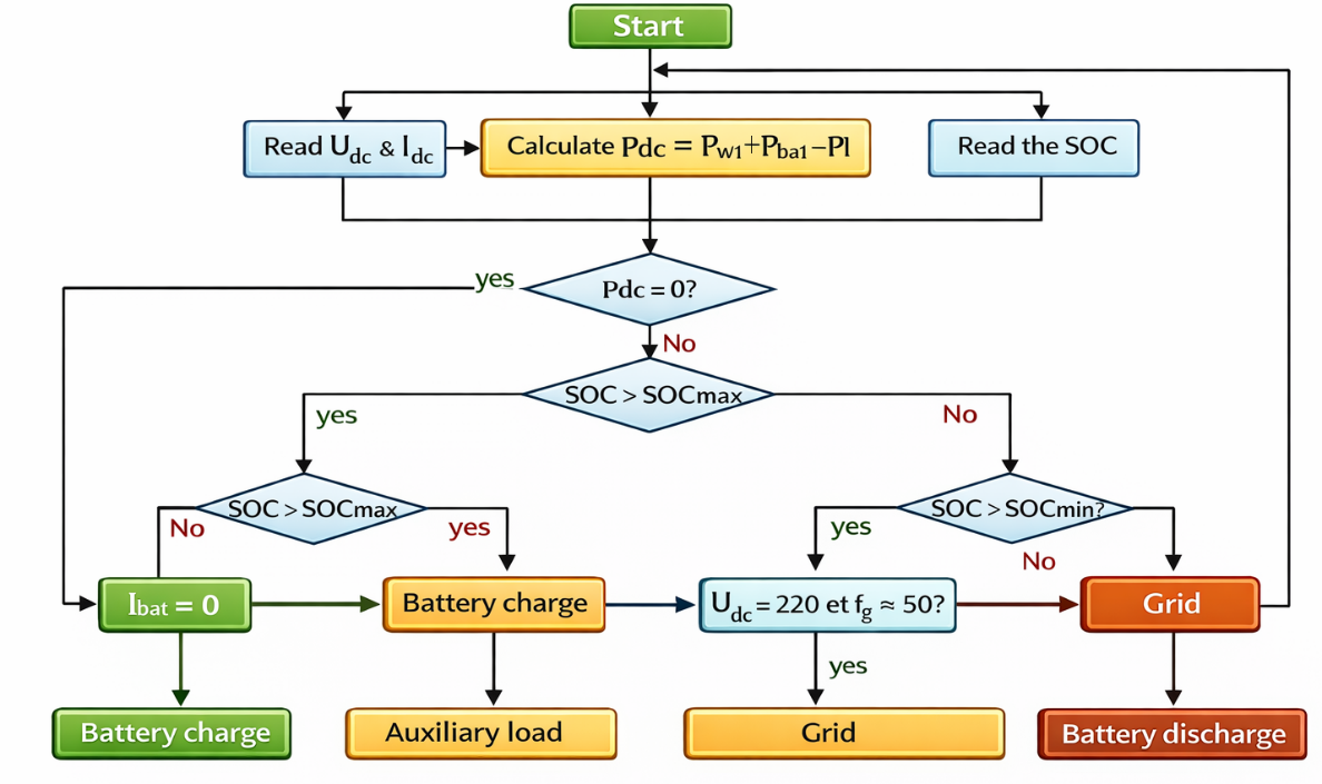
- Flowchart of the hybrid system power management algorithm
FNN Technique
In order to enhance the flexibility and intelligence of the hybrid EMS suggested, an FNN is included as the decision-making core. The neural network is trained to learn the nonlinear mapping between key electrical parameters and the optimum control actions required for system coordination. The neural network serves as an intelligent controller with the ability to dynamically alter switching decisions in accordance with real-time system conditions.
The system flowchart (Figure 5) shows that the neural network takes in four important input features: Battery SoC: shows how much energy is in the storage system, Total Power: shows the total power that the system is using or making, and Grid Voltage. ): shows how stable the grid connection is; and Grid Frequency (
 ): used to find problems or irregularities in the grid.
These inputs define the present state of the hybrid system and provide a general overview of the external and internal electric environment. The trained neural network produces the optimum control commands for: Grid switch (connect/disconnect the grid); Load switch (enable/disable local load supply); Operating mode selection (islanded or grid-connected); Auxiliary load activation (optional support systems).
The neural network is structured in an input layer (4neurons), one or more hidden layers (nonlinear transformations), and an output layer (4 neurons), which directly control the grid switch, load switch, auxiliary load, and the mode of operation. Each layer of the network processes the inputs through the subsequent operations:
| 
| (16) |
| 
| (17) |
Where  is the pre-activation output (weighted input) of layer
  ;
;  is the weight matrix;
  is the bias vector;
  is the activation from the previous layer;
  is the activation function, typically ReLU for hidden layers and sigmoid for the output layer.
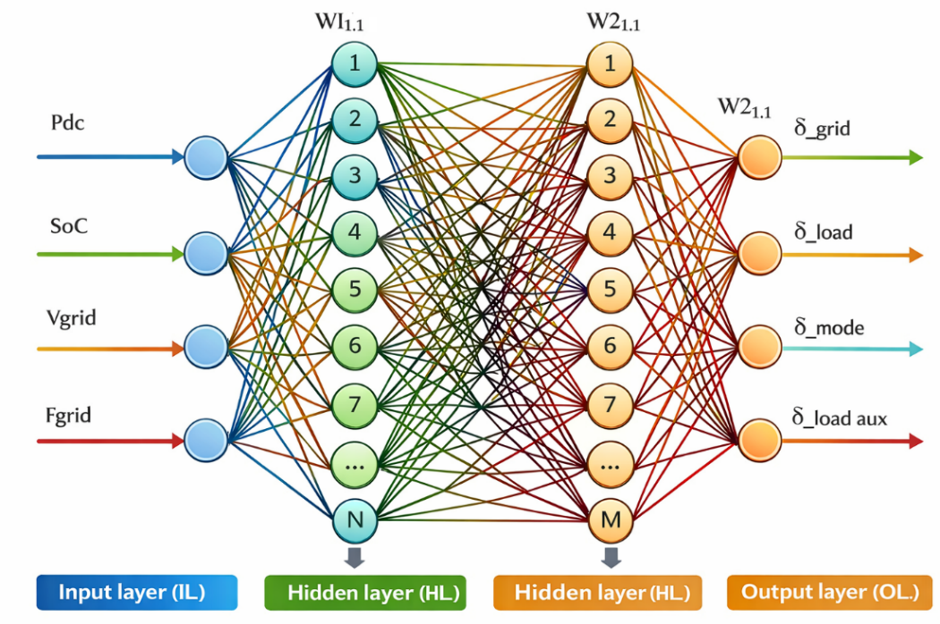
- The developed ANN architecture
Each of the neurons in the output layer produces a value between 0 and 1, which is considered to be a binary decision: values above 0.5 enable a control action (ON), while values below 0.5 turn it off (OFF). This binary decision-making conforms to the logic described in the system flowchart, where each output corresponds to a specific energy management function.
This architecture allows the system to adapt to varying electrical conditions autonomously and make decisions in real time with great efficacy. The neural network picks up these decisions through supervised learning on labeled operational data, minimizing the discrepancy between predicted and target output via a loss function such as mean squared error or binary cross-entropy.
The regression coefficient (R) for ANN training is 0.99963, indicating a strong correlation. The ANN parameters, including the number of inputs, number of outputs, number of hidden layers, number of neurons in each hidden layer (N, M), learning rate, and number of iterations, are summarized in Table 1.
- ANN parameters
Parameters | Value |
Number of inputs | 4 |
Number of outputs | 4 |
Number of hidden layers | 2 |
Number of neurons in the hidden layer N | 18 |
Number of neurons in the hidden layer M | 20 |
Number of iterations | 1000 |
Learning rate | 6.9302 |
Modes of Operation
The suggested energy management system can work in two main ways, depending on whether the utility grid is available and how much renewable energy is generated, stored, and needed. These operational states make sure that the power supply is always reliable, that renewable resources are used to their fullest, and that the system stays stable. When the system is connected to the utility grid, the renewable energy it makes is mostly used to meet the needs of the local load. When the renewable generation is more than the load demand and the energy storage system is full, the extra energy can be sent to the utility grid. This mode of operation stops the battery from overcharging and makes better use of the energy overall. In these situations, the grid power can be written as
| 
| (18) |
This section primarily explores the derivation of the nonlinear control law employed to oversee energy transmission among the battery, load, and grid. Additionally, it elucidates the regulation of the dc-link voltage. The design methodology relies on an input-output feedback linearization approach. Unlike conventional methods, the bi-directional buck-boost converter, rather than the grid-side converter, is employed to regulate the dc-link voltage. The dynamic equation of this converter is derived from the power balance equation of the back-to-back converter. Which is given by (18). As long as the renewable generation is more than the load demand and the battery state of charge is met
| 
| (19) |
On the other hand, when the renewable generation and stored energy aren't enough to meet the load demand, the utility grid provides the extra power to keep things running smoothly. In this case, the grid makes up for the difference between the power generated by the renewable source and the battery system and the load demand. This can be shown as
| 
| (20) |
When
| 
| (21) |
Without the utility grid, the system runs on its own, with only renewable generation and the energy storage system meeting the load demand. In this case, the energy balance must meet:
| 
| (22) |
To make the most of clean energy sources and cut down on battery cycling, renewable energy generation is given priority. When the renewable energy produced is more than the load demand, the extra energy is stored in the battery system for later use.
| 
| (23) |
For
| 
| (24) |
The battery system makes up for the power shortfall when the renewable generation is less than the load demand in order to keep the supply going. If the renewable energy generation and stored energy aren't enough, and the battery's state of charge drops below the minimum level:
| 
| (25) |
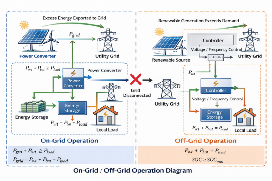
To keep the battery from running out too quickly and to make the storage system last longer, the load can be temporarily disconnected. The proposed energy management strategy uses artificial intelligence to make the system more flexible and durable. The neural network-based approach is better at dealing with uncertainties that come up with renewable energy intermittency, grid disturbances, and dynamic load changes than traditional rule-based control methods. This makes decision-making easier and keeps the system running smoothly. Figure 6 shows how the proposed energy management system works, with both On-Grid and Off-Grid setups. It also shows how power flows between renewable sources, energy storage, local loads, and the utility grid.
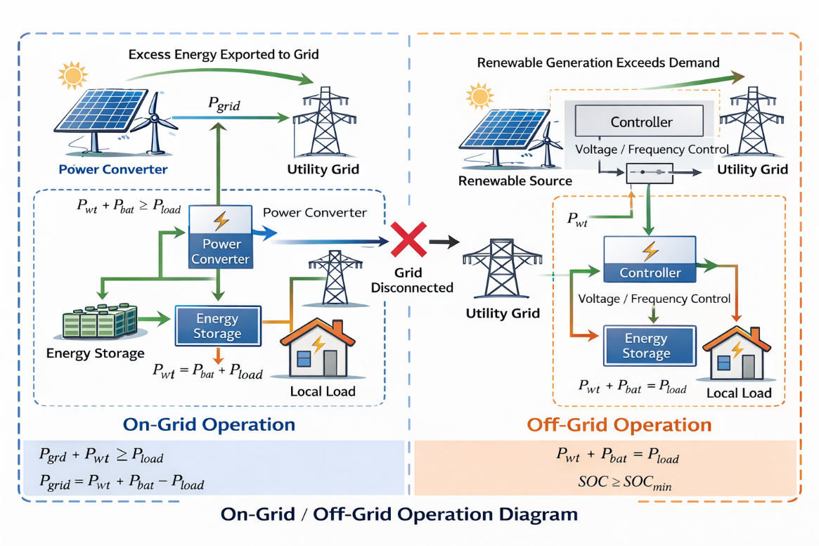
- On-Grid / Off-Grid operation diagram
RESULTS AND DISCUSSIONS
Simulation results of intelligent EM in a hybrid wind-battery system, operating in grid-connected or standalone mode, demonstrate significant improvements in energy efficiency. Using FNN learning, power distribution among sources and storage adapts dynamically to climatic variations and load demands. Performance evaluation is based on detailed analyses under different scenarios, considering environmental profiles such as wind speed (Figure 7), load power at 5000 W, and grid faults in voltage and frequency (Figure 8 and Figure 9). In grid-connected mode, the FNN adjusts energy injection or absorption based on grid stability; in standalone mode, it optimizes self-consumption and storage to ensure autonomous and reliable operation, thereby enhancing system resilience. The system parameters are listed in Table 2.
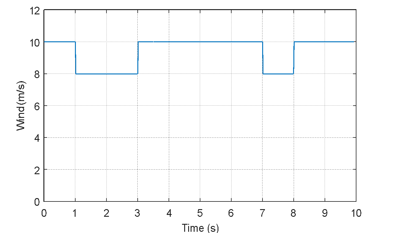
- Profile of the wind velocity
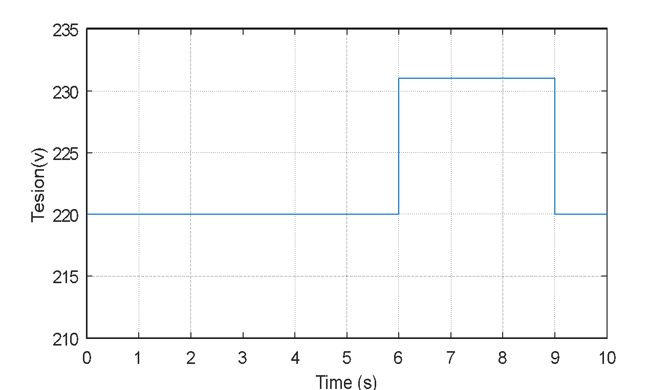
- Grid voltage
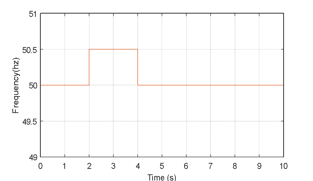
- Grid frequency
- System parameters
The Components | Values |
Wind generator | Power rating | 2700W |
Battery bank | Rated voltage | 200V |
Capacity | 100AH |
DC bus | Voltage | 630V |
Load | Minimum power | 1000W |
Maximum power | 5000W |
Grid | Effective voltage value | 220V |
Maximum voltage value | 381V |
Case 1
Load flow analysis generates the dataset for neural network training. In the first case, with the wind system operating at maximum power, surplus energy is injected into the grid if SOC ≥ SOC_max; otherwise, it is stored in the batteries. In the second case, when wind generation is insufficient, batteries supply the deficit if SOC ≥ SOC_min, or the grid compensates. In the third case, wind generation only covers load demands without surplus. In critical standalone conditions, the supervisor prioritizes load shedding to preserve battery life and system balance.
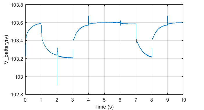
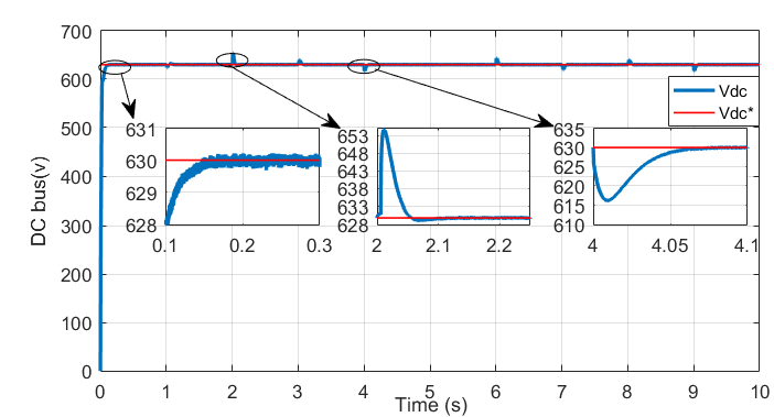
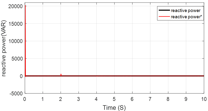
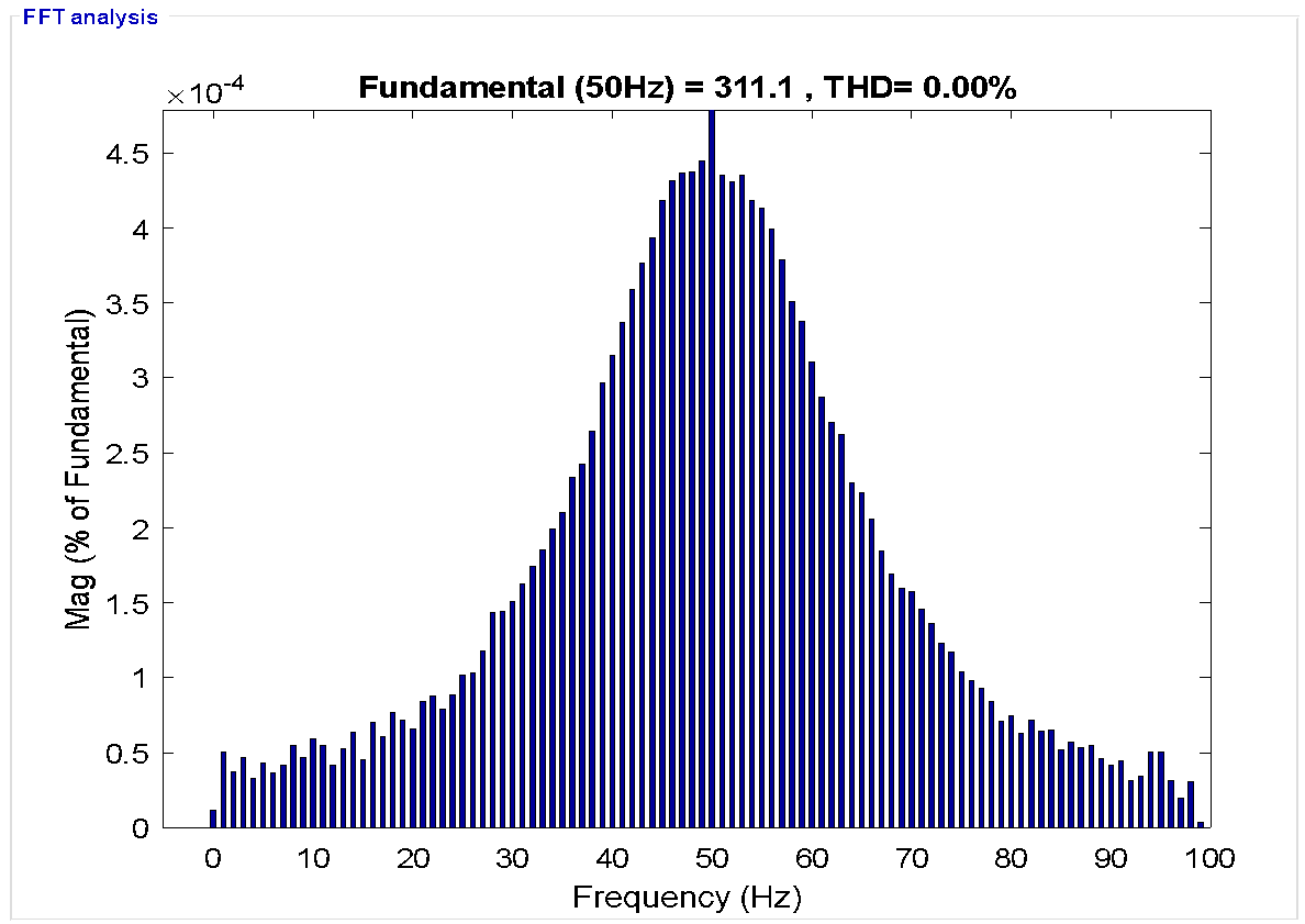
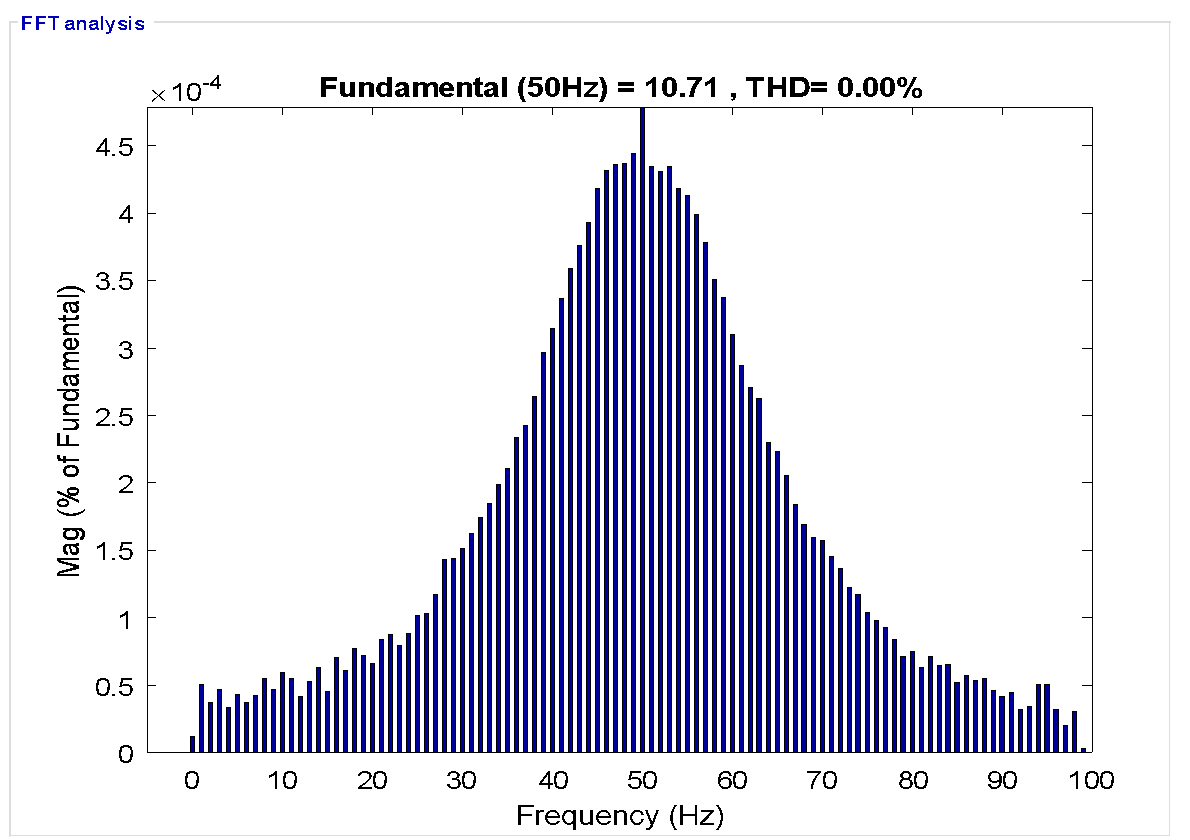
0 s to 1 s: The wind generator produces maximum power (blue curve), partially consumed by the load (red curve) while the surplus charges the batteries (green curve), increasing the SOC (Figure 10), battery current (Figure 11), and voltage (Figure 12). The DC voltage shows excellent reference tracking (Figure 13), and reactive power accurately follows its reference (Figure 14). FFT analysis (Figure 15 and Figure 16) reveals zero THD, confirming grid-imposed voltage and frequency. 1 s to 2 s: Wind generation becomes insufficient, and the batteries discharge to maintain load supply, leading to a decrease in SoC, a reversal in battery current (Figure 11), and a voltage drop (Figure 12), confirming the transition from charging to discharging. 4 s to 6 s: The wind generator again produces enough energy to supply the load, with surplus power stored in the batteries.
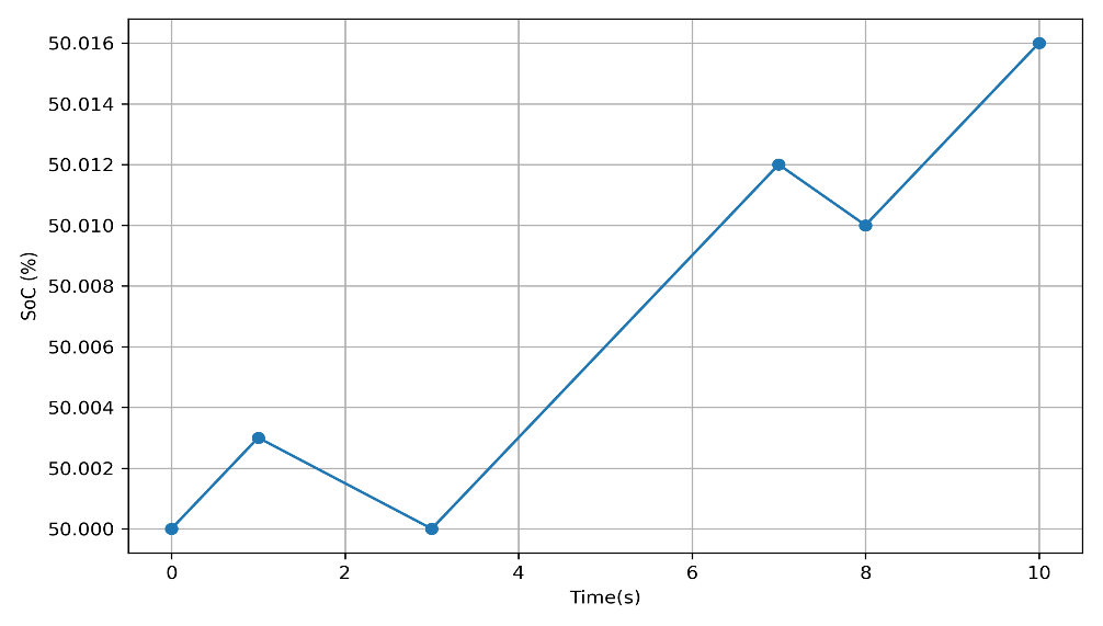
- SoC
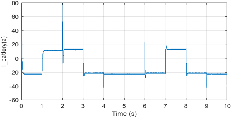
- Battery current
- The battery voltage
- Vdc voltage
- Reactive power
- Voltage Harmonic spectrum (ON mode)
- Current harmonic spectrum (ON mode)
Case 2: Mode M2 (Standalone Mode)
The hybrid system, composed of a wind generator, storage system, and AC load, operates autonomously to meet load demands, managed by the energy management algorithm. 0 to 1 s: At t = 2 s, a grid fault causes a frequency rise beyond limits, prompting the supervisor to disconnect from the grid. The wind generator cannot fully supply the load, and the storage system compensates, with the SOC dropping to 50% before recovering. The load current and voltage are depicted in Figure 17 and Figure 18, respectively. The grid voltage and current are depicted in Figure 19 and Figure 20, respectively. 3 to 4 s: Increased wind speed enables the wind generator to supply the load and store surplus energy in the batteries. The wind system current is depicted in Figure 21. 6 to 7 s: A second grid fault due to overvoltage cuts the grid supply to zero. The system's reactive power is around zero in Figure 22. The wind generator continues powering the load, and surplus energy charges the batteries, increasing SOC. FFT analysis (Figure 23 and Figure 24) shows a 3.92% THD, confirming standalone operation and indicating that voltage and frequency regulation are not fully optimized.

- Load current
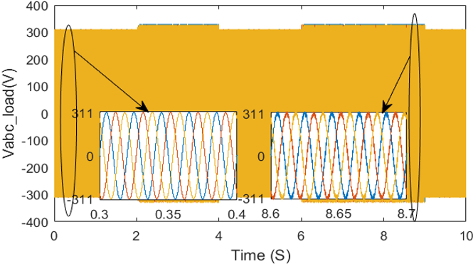
- 3ph Voltage of the load
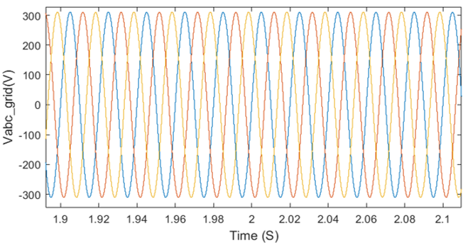
- 3ph Voltage of the grid
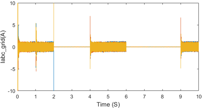
- Grid current
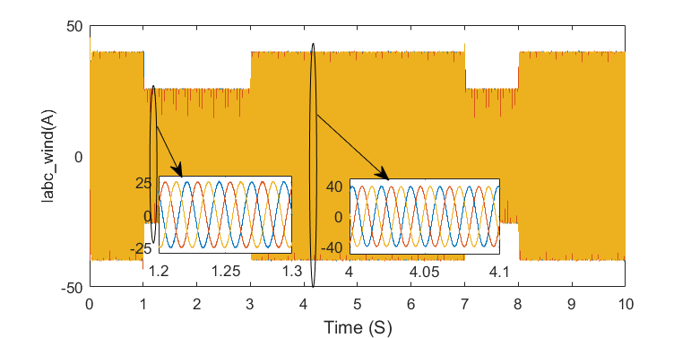
- Current of WT generator
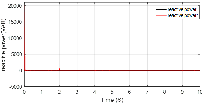
- Reactive power
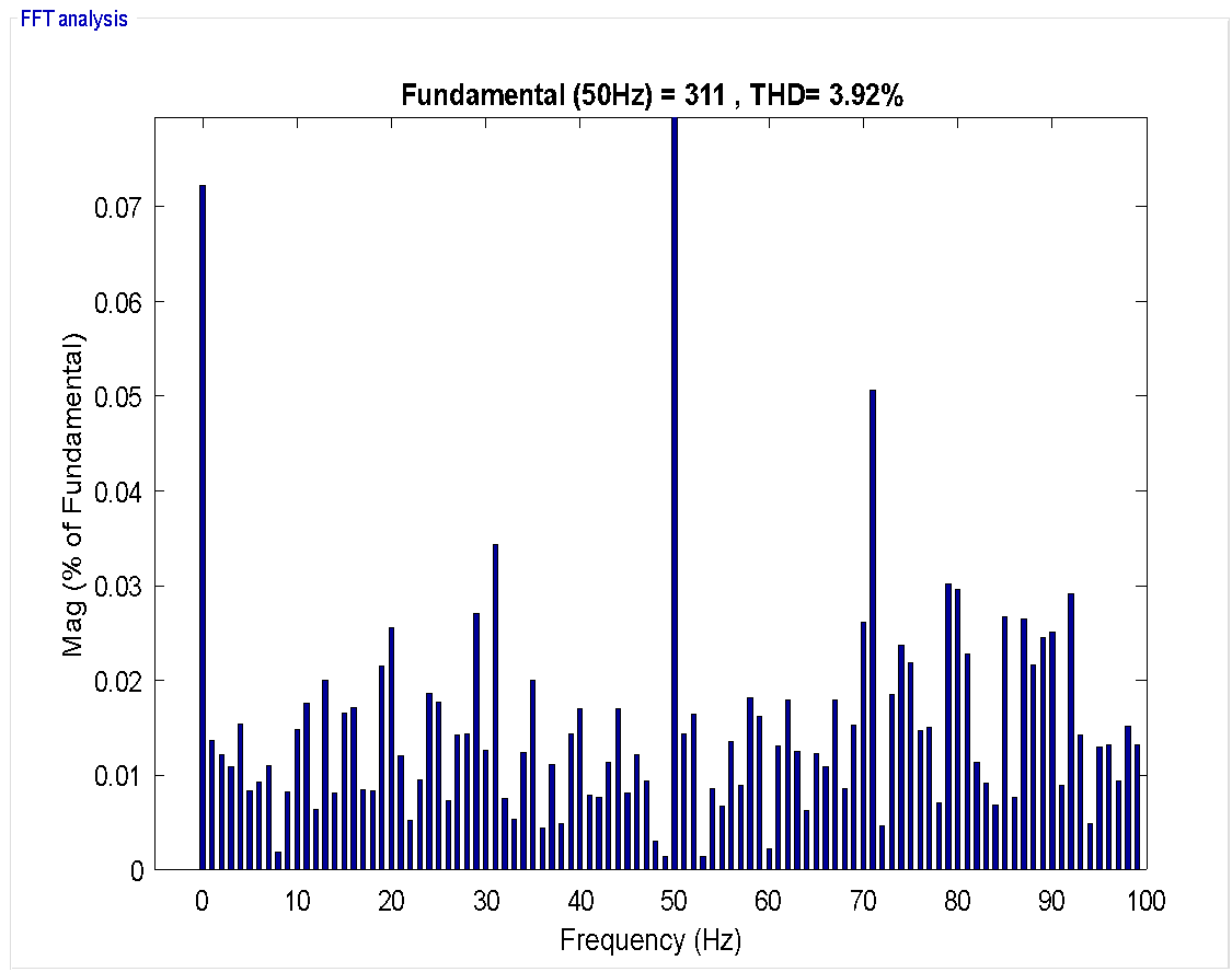
- Voltage harmonic spectrum (Off mode)
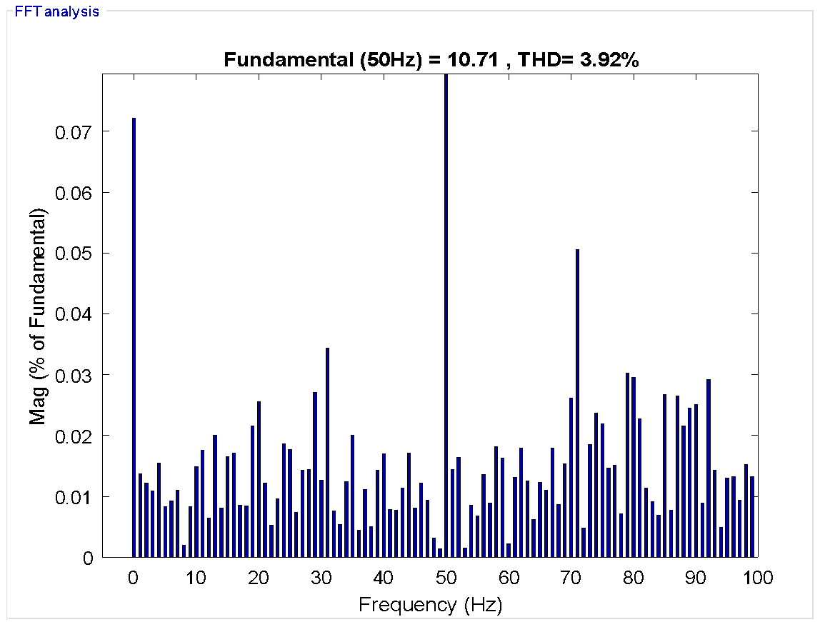
- Current harmonic spectrum (Off mode)
Target-Based Training Process
Simulation results over 10 seconds, starting with a 50% battery SOC, confirm the efficiency of the proposed management strategy. Figure 25 illustrates that the wind system can serve as the primary energy source. Mode M1 (Grid-Connected Mode) The hybrid system, composed of a wind generator, battery banks, and a load, is connected to the electrical grid, with the wind turbine operating in MPPT mode throughout the simulation.
The target-based training strategy's effectiveness is demonstrated by the regression analysis between the predicted outputs and the corresponding target values, as shown in Figure 25. The plots show how the training, validation, testing, and overall datasets are related to each other. In every case, the predicted outputs have a strong linear relationship with the target values. This shows that the model can accurately learn how to map the input features to the desired outputs. One important thing to note from the regression plots is how closely the data points line up with the reference line Y=T. This line shows the best-case scenario for the prediction, where the model output perfectly matches the target. The fitted regression lines are almost exactly like this ideal line. This means that the learning algorithm has done a good job of reducing the prediction error during the training phase. The slopes of the regression lines are about the same as one, and the intercepts are still close to zero. This further shows that the learned model is strong and accurate.
In addition, the fact that the training, validation, and testing datasets all show the same results suggests that the proposed model does not overfit and can generalize well. The small spread of the data points around the regression line shows that the learning process is stable and that the target-based optimization strategy works well to steer the network parameters toward the best solution. In general, these results show that the target-based training process is a reliable framework for model learning, ensuring accurate prediction performance and strong agreement between predicted and desired outputs across all data subsets. This confirms the suitability of the proposed approach for predictive modeling and system identification tasks.
The power management waveforms of the hybrid system are shown in Figure 26. The plot highlights the dynamic distribution of power among the wind turbine, battery storage, and various loads. It can be observed that the control strategy effectively balances the generated power with the demanded load, while maintaining the battery within safe operational limits. The transitions between different power sources are smooth, demonstrating the stability and responsiveness of the hybrid management algorithm. Moreover, the waveforms confirm that the system can efficiently handle fluctuations in wind power while ensuring a continuous power supply to both auxiliary and primary loads.
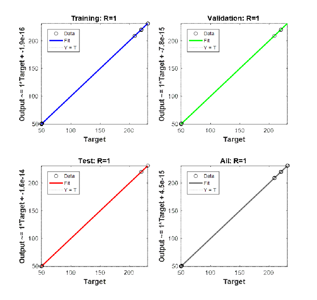
- Target-based training process
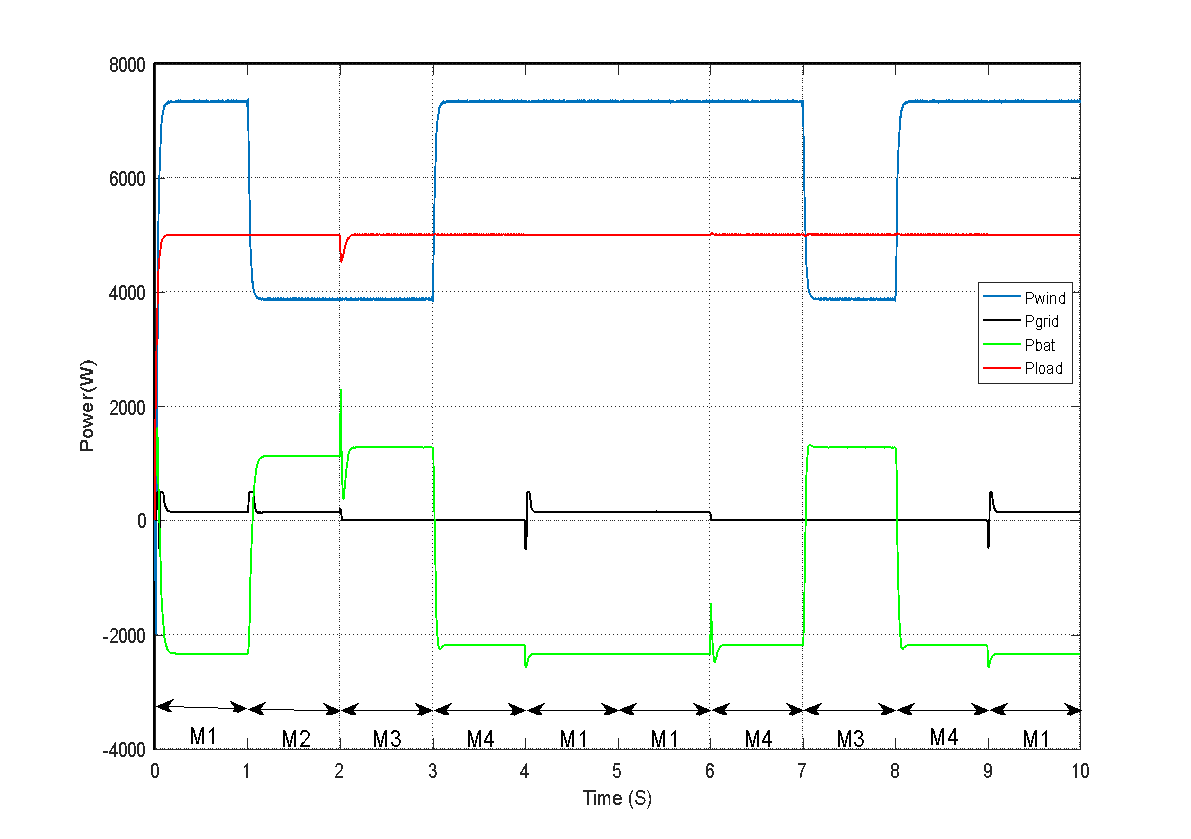
- Power management of the hybrid system waveforms
CONCLUSION
The introduced intelligent management system enables various operating modes tailored to different weather conditions, ensuring smooth and rapid power delivery from each source while considering the state of charge of the battery bank. This system is based on an advanced strategy that optimizes the use of renewable energy resources by dynamically adjusting input according to climatic variations and consumption needs. Among the key achievements is a significant increase in delivered power, thereby reducing losses and improving the overall efficiency of the system. Additionally, battery bank usage is optimized through smarter and more balanced charge-discharge management, which helps extend battery lifespan and lower maintenance costs. Finally, this approach ensures intelligent and adaptive energy system management, promoting better integration of renewable sources and greater resilience to climate variations. Thus, it offers a high-performance, sustainable alternative to conventional methods, paving the way for more autonomous and efficient energy systems.
DECLARATION
Author Contribution
All authors contributed equally to the main contributor to this paper. All authors read and approved the final paper.
Funding
This article has been produced with the financial support of the European Union under the REFRESH—Research Excellence For REgion Sustainability and High-tech Industries project number CZ.10.03.01/00/22_003/0000048 via the Operational Programme Just Transition.
Acknowledgement
This article has been produced with the financial support of the European Union under the REFRESH—Research Excellence For REgion Sustainability and High-tech Industries project number CZ.10.03.01/00/22_003/0000048 via the Operational Programme Just Transition. Also, the authors wish to express their deep gratitude to the Ministry of Higher Education and Scientific Research of Algeria for its essential support in carrying out this study.
Conflicts of Interest
The authors declare no conflict of interest.
ABBREVIATIONS
The following abbreviations are used in this manuscript.
WECS | : | Wind Energy Conversion System |
EMC | : | Energy management control |
GW | : | Gigawatts |
MPPT | : | Maximum Power Point Tracking |
MGs | : | Microgrids |
WE | : | Wind energy |
DERs | : | Distributed energy resources |
PV | : | Photovoltaic |
ESSs | : | Energy storage systems |
EMS | : | Energy management system |
RBFNN | : | Radial Basis Function Neural Network |
PMSG | : | Permanent Magnet Synchronous Generator |
GSC | : | Grid-side converter |
MSC | : | Machine-side converter |
SoC | : | State of charge |
FNN | : | Feedforward neural network |
REFERENCES
- A. Assas, H. Guentri, T. Alaoui, V. Blazek, A. Dahbi, A. Ma'arif, E. Touti, and M. M. Mahmoud, "Robust LQR Control Design for High Efficiency Battery Supercapacitor Hybrid Storage Systems," International Journal of Robotics and Control Systems, vol. 6, no. 2, pp. 1405–1425, 2026, https://pubs2.ascee.org/index.php/IJRCS/article/view/1933.
- S. Heroual, B. Belabbas, K. Ayati, R. Haloui, A. T. Hassan, A. Ma'arif, M. M. Mahmoud, and V. Blazek, "Genetic Algorithm Tuned Controllers for High-Performance Indirect Field-Oriented Control in DFIG-Based WECS," Buletin Ilmiah Sarjana Teknik Elektro, vol. 8, no. 1, pp. 294–310, Feb. 2026, http://journal2.uad.ac.id/index.php/biste/article/view/15529/6376.
- N. M. Tahir, A. Y. Babawuro, F. M. Alelaj, B. B. Muhammad, S. S. Shitu, and I. A. Umar, "Control of a Single-Link Flexible Manipulator: Integration of Output-Based Filter With Model Predictive Constraint," Journal of Physics: Conference Series, vol. 3191, no. 1, p. 012043, 2026, https://doi.org/10.1088/1742-6596/3191/1/012043.
- R. E. S. Irena. International renewable energy agency. Abu Dhabi, 2020., 2023, https://www.irena.org/Publications/2023/Mar/Renewable-capacity-statistics-2023.
- A. Raj, A. Nandi, S. K. Sawant, A. K. Swain, A. P. Yadav, A. K. Parida, M. M. Mahmoud, V. Blazek, D. E. M. Wapet, and S. N. Fahmy, "Adaptive Q-Wavelet Transform and Kalman Filtering for Power Quality Disturbance Prediction and Carbon Emission Impact Analysis in Smart Grids," Engineering Reports, vol. 8, no. 5, p. e70825, 2026, https://doi.org/10.1002/eng2.70825.
- M. T. Mohamed, I. M. Elzein, M. M. Mahmoud, A. M. El-Rifaie, H. S. Hussein, W. F. Mbasso, and A. M. Ewais, "Intelligent Frequency Regulation in Islanded Microgrids Using a Crayfish-Tuned FO–(PD–PI) Controller With Energy Storage Coordination," Journal of Low Frequency Noise, Vibration and Active Control, p. 14613484261429576, 2026, https://doi.org/10.1177/14613484261429576.
- M. Miloudi, H. Miloudi, S. A. E. M. Ardjoun, I. M. Elzein, M. M. Mahmoud, W. F. Mbasso, H. S. Hussein, and A. M. Ewais, "Comprehensive Experimental Performance Investigation of Conducted Electromagnetic Interference in Split-Phase Induction Motors: Common-Mode," Journal of Low Frequency Noise, Vibration and Active Control, vol. 45, no. 2, pp. 861–880, 2026, https://doi.org/10.1177/14613484251411703.
- J. M. Raya-Armenta, N. Bazmohammadi, J. G. Avina-Cervantes, D. Sáez, J. C. Vasquez, and J. M. Guerrero, "Energy Management System Optimization in Islanded Microgrids: An Overview and Future Trends," Renewable and Sustainable Energy Reviews, vol. 149, p. 111327, 2021, https://doi.org/10.1016/j.rser.2021.111327.
- A. T. Hassan, I. M. Elzein, M. M. Mahmoud, V. Blazek, A. Ma'arif, E. Touti, and A.-M. M. Ali, "Intelligent Chopper and RSC Control Using Crayfish Optimization for Dynamic Stability and Fault Ride-Through of DFIG Wind Turbines," International Journal of Robotics and Control Systems, vol. 6, no. 1, pp. 693–717, 2026, https://doi.org/10.31763/ijrcs.v6i1.2002.
- M. Tarek and M. I. M. Elzein, "Sustainable Energy Management in Islanded Microgrids via HHO-BE Tuned Adaptive Controllers and Demand-Side Flexibility," Engineering Reports, vol. 8, no. 1, p. e70561, 2026, https://doi.org/10.1002/eng2.70561.
- B. Dey, S. Misra, and F. P. Garcia Marquez, "Microgrid System Energy Management With Demand Response Program for Clean and Economical Operation," Applied Energy, vol. 334, p. 120717, 2023, https://doi.org/10.1016/j.apenergy.2023.120717.
- M. E. T. Souza Junior and L. C. G. Freitas, "Power Electronics for Modern Sustainable Power Systems: Distributed Generation, Microgrids and Smart Grids—A Review," Sustainability, vol. 14, no. 6, p. 3597, 2022, https://doi.org/10.3390/su14063597.
- D. Cui, A. Harrison, E. Fendzi-Donfack, I. Dagal, P. Jangir, M. M. Mahmoud, P. Malkani, W. F. Mbasso, P. Tiako, and A. Smerat, "Enhancing Short-Term Electricity Forecasting With Advanced Machine Learning Techniques," Journal of Electrical Engineering & Technology, vol. 21, no. 1, pp. 147–187, 2026, https://doi.org/10.1007/s42835-025-02430-z.
- B. Benlahbib, N. Bouarroudj, S. Mekhilef, A. Dahbi, T. Abdelkrim, F. Bouchafaa, and A. Lakhdari, "Experimental Investigation of Power Management and Control of a PV/Wind/Fuel Cell/Battery Hybrid Energy System Microgrid," International Journal of Hydrogen Energy, vol. 45, no. 53, pp. 29110–29122, 2020, https://doi.org/10.1016/j.ijhydene.2020.07.251.
- M. Basu, C. Jena, M. M. Hussein, I. M. Elzein, A. M. El-Rifaie, D. E. M. Wapet, E. Touti, and M. M. Mahmoud, "Flexible Dynamic Optimal Power Flow Integrating Renewable Energy Sources and Electric Vehicle Parking IoT," Engineering Reports, vol. 7, no. 12, p. e70568, 2025, https://doi.org/10.1002/eng2.70568.
- N. F. Ibrahim, I. M. Elzein, M. M. Mahmoud, A. M. El-Rifaie, H. S. Hussein, and M. A. E. Eid, "Enhanced Control of Single-Stage PV-STATCOM Using Hybrid MPPT and Adaptive AHLMS for Power Quality Improvement," IEEE Access, vol. 13, pp. 200253–200270, 2025, https://doi.org/10.1109/ACCESS.2025.3635707.
- A. Hysa, S. Sefa, I. M. Elzein, A. Ma'arif, M. M. Mahmoud, and E. Touti, "Advanced Modeling and Comparative Error Analysis of Photovoltaic Cells Using Multi-Diode Models and EQE Characterization," Journal of Robotics and Control, vol. 6, no. 5, pp. 2308–2321, 2025, https://doi.org/10.18196/jrc.v6i5.27539.
- P. Sinha, K. Paul, I. M. Elzein, M. M. Mahmoud, A. M. El-Rifaie, W. F. Mbasso, and A. M. Ewais, "Classifying Power Quality Issues in Railway Electrification Systems Using a Nonsubsampled Contourlet Transform Approach," Engineering Reports, vol. 7, no. 8, p. e70301, 2025, https://doi.org/10.1002/eng2.70301.
- Y. Maamar, I. M. Elzein, A. Benameur, H. Mohamed, M. M. Mahmoud, M. I. Mosaad, and S. A. Shaaban, "A Comparative Analysis of Recent MPPT Algorithms (P&O/INC/FLC) for PV Systems," Journal of Robotics and Control, vol. 6, no. 4, pp. 1581–1588, 2025, https://doi.org/10.18196/jrc.v6i4.25814.
- R. Bousseksou, N. Bessous, I. M. Elzein, M. M. Mahmoud, A. Ma'arif, E. Touti, A. Al-Quraan, and N. Anwer, "Utilizing Short-Time Fourier Transform for the Diagnosis of Rotor Bar Faults in Induction Motors Under Direct Torque Control," International Journal of Robotics and Control Systems, vol. 5, no. 2, pp. 1441–1457, 2025, https://doi.org/10.31763/ijrcs.v5i2.1886.
- S. Basu, M. Basu, C. Jena, I. M. Elzein, W. F. Mbasso, M. M. Mahmoud, A. Ma'arif, K. A. Metwally, and S. A. Shaaban, "Applications of Snow Ablation Optimizer for Sustainable Dynamic Dispatch of Power and Natural Gas Assimilating Multiple Clean Energy Sources," Engineering Reports, vol. 7, no. 6, Art. no. e70211, 2025, https://doi.org/10.1002/eng2.70211.
- B. N. Alhasnawi and B. H. Jasim, "A New Energy Management System of On-Grid/Off-Grid Using Adaptive Neuro-Fuzzy Inference System," Journal of Engineering Science and Technology, vol. 15, no. 6, pp. 3903–3919, 2020, https://jestec.taylors.edu.my/Vol%2015%20issue%206%20December%202020/15_6_27.pdf.
- R. S. Jadhav and S. S. B. Patil, "Design and Implementation of PV-Wind Battery Hybrid System for Off-Grid and On-Grid," in Proceedings of the 4th International Conference on Inventive Systems and Control (ICISC), pp. 612–618, 2020, https://doi.org/10.1109/ICISC47916.2020.9171150.
- C. Ceylan and Y. Devrim, "Green Hydrogen Based Off-Grid and On-Grid Hybrid Energy Systems," International Journal of Hydrogen Energy, vol. 48, no. 99, pp. 39084–39096, 2023, https://doi.org/10.1016/j.ijhydene.2023.02.031.
- J. M. Tabora, U. C. Paixão Júnior, C. E. M. Rodrigues, U. H. Bezerra, M. E. D. L. Tostes, B. S. Albuquerque, E. O. Matos, and A. A. Nascimento, "Hybrid System Assessment in On-Grid and Off-Grid Conditions: A Technical and Economical Approach," Energies, vol. 14, no. 17, p. 5284, 2021, https://doi.org/10.3390/en14175284.
- W. Bai, M. Sechilariu, and F. Locment, "On-Grid/Off-Grid DC Microgrid Optimization and Demand Response Management," in Proceedings of the 2020 22nd European Conference on Power Electronics and Applications (EPE'20 ECCE Europe), pp. 1–10, 2020, https://doi.org/10.23919/EPE20ECCEEurope43536.2020.9215679.
- H. Vaikund and S. G. Srivani, "Demand Response-Based Cost Mitigation Strategy in Renewable Energy Connected Microgrid Using Intelligent Energy Management System," Electrical Engineering, vol. 106, no. 1, pp. 1033–1052, 2024, https://doi.org/10.1007/s00202-023-02034-8.
- S. Heroual, B. Belabbas, I. M. Elzein, Y. Diab, A. Ma'arif, M. M. Mahmoud, and T. Alaoui, "Enhancement of Transient Stability and Power Quality in Grid-Connected PV Systems Using SMES," International Journal of Robotics and Control Systems, vol. 5, no. 2, pp. 990–1005, 2025, https://doi.org/10.31763/ijrcs.v5i2.1760.
- T. Boutabba, I. Benlaloui, F. Mechnane, I. M. Elzein, M. Ammar, and M. M. Mahmoud, "Design of a Small Wind Turbine Emulator for Testing Power Converters Using dSPACE 1104," International Journal of Robotics and Control Systems, vol. 5, no. 2, pp. 698–712, 2025, https://doi.org/10.31763/ijrcs.v5i2.1685.
- O. M. Kamel, I. M. Elzein, M. M. Mahmoud, A. Y. Abdelaziz, M. M. Hussein, and A. A. Z. Diab, "Effective Energy Management Strategy With a Novel Design of Fuzzy Logic and JAYA-Based Controllers in Isolated DC/AC Microgrids: A Comparative Analysis," Wind Engineering, vol. 49, no. 1, pp. 199–222, 2025, https://doi.org/10.1177/0309524X241263518.
- S. A. Mohamed, N. Anwer, and M. M. Mahmoud, "Solving Optimal Power Flow Problem for IEEE-30 Bus System Using a Developed Particle Swarm Optimization Method: Towards Fuel Cost Minimization," International Journal of Modelling and Simulation, vol. 45, no. 1, pp. 307–320, 2025, https://doi.org/10.1080/02286203.2023.2201043.
- A. Maheshwari, S. Nageswari, R. Palanisamy, B. Karthikeyan, M. M. Mahmoud, D. E. M. Wapet, A. M. El-Rifaie, E. Touti, and A. I. Omar, "Real-Time Parameter Identification and State of Charge Estimation of Electric Vehicle Batteries," Engineering Reports, vol. 7, no. 8, p. e70346, 2025, https://doi.org/10.1002/eng2.70346.
- S. Heroual, B. Belabbas, Y. Diab, M. M. Mahmoud, T. Allaoui, and N. Benabdallah, "Optimizing Power Flow in Photovoltaic-Hybrid Energy Storage Systems: A PSO and DPSO Approach for PI Controller Tuning," International Transactions on Electrical Energy Systems, vol. 2025, no. 1, p. 9958218, 2025, https://doi.org/10.1155/etep/9958218.
- P. Sinha, K. Paul, A. Mohanty, I. M. Elzein, C. S. Mishra, M. M. Mahmoud, D. E. M. Wapet, A. Al Ayidh, A. Althobaiti, H. S. Hussein, T. A. H. Alghamdi, and A. M. Ewais, "Efficient Automated Detection of Power Quality Disturbances Using Nonsubsampled Contourlet Transform & PCA-SVM," Energy Exploration & Exploitation, vol. 43, no. 3, pp. 1149–1179, 2025, https://doi.org/10.1177/01445987241312755.
- F. Menzri, T. Boutabba, I. Benlaloui, H. Bawayan, M. I. Mosaad, and M. M. Mahmoud, "Applications of Hybrid SMC and FLC for Augmentation of MPPT Method in a Wind-PV-Battery Configuration," Wind Engineering, vol. 48, no. 6, pp. 1186–1202, 2024, https://doi.org/10.1177/0309524X241254364.
- A. Fatah, T. Boutabba, I. Benlaloui, S. Drid, M. M. Mahmoud, M. M. Hussein, W. F. Mbasso, H. S. Hussein, and A. M. Ewais, "Design and Dynamic Evaluation of a Novel Photovoltaic Pumping System Emulation With DS1104 Hardware Setup: Towards Innovative in Green Energy Systems," PLOS ONE, vol. 19, no. 10, p. e0308212, 2024, https://doi.org/10.1371/journal.pone.0308212.
- F. Alelaj and A. Alqallaf, "Impact of Solar Irradiation on the Performance Ratio of the Photovoltaic Module," in Proceedings of the 2019 IEEE 10th GCC Conference & Exhibition (GCC), pp. 1–4, 2019, https://doi.org/10.1109/GCC45510.2019.9087579.
- V. Kumar, R. N. Rao, M. F. Ansari, V. Shekher, K. Paul, P. Sinha, A. Alkuhayli, U. Khaled, and M. M. Mahmoud, "A Novel Hybrid Harris Hawk Optimization-Sine Cosine Algorithm for Congestion Control in Power Transmission Network," Energies, vol. 17, no. 19, p. 4985, 2024, https://doi.org/10.3390/en17194985.
- R. Kassem, N. F. Ibrahim, M. M. Mahmoud, A. Alkuhayli, U. Khaled, A. Beroual, and H. M. I. Saleeb, "Enhanced Multiphase Interleaved Boost Converter Interface for Grid-Connected PV Power System," IEEE Access, vol. 12, pp. 151940–151954, 2024, https://doi.org/10.1109/ACCESS.2024.3469540.
- F. Menzri, T. Boutabba, I. Benlaloui, L. Chrifi-Alaoui, A. Alkuhayli, U. Khaled, and M. M. Mahmoud, "Applications of Novel Combined Controllers for Optimizing Grid-Connected Hybrid Renewable Energy Systems," Sustainability, vol. 16, no. 16, p. 6825, 2024, https://doi.org/10.3390/su16166825.
- F. Alelaj and A. Alqallaf, "Optimization of the Tilt Angle of the Photo-Voltaic Module in Kuwait," in Proceedings of the 2019 IEEE 10th GCC Conference & Exhibition (GCC), 2019, pp. 1–6, https://www.doi.org/10.1109/GCC45510.2019.1570525127.
- H. Alnami, S. A. E. M. Ardjoun, and M. M. Mahmoud, "Design, Implementation, and Experimental Validation of a New Low-Cost Sensorless Wind Turbine Emulator: Applications for Small-Scale Turbines," Wind Engineering, vol. 48, no. 4, pp. 565–579, 2024, https://doi.org/10.1177/0309524X231225776.
- B. S. Atia, M. M. Mahmoud, I. M. Elzein, A.-M. M. Abdel-Rahim, A. Alkuhayli, U. Khaled, A. Beroual, and S. A. Shaaban, "Applications of Kepler Algorithm-Based Controller for DC Chopper: Towards Stabilizing Wind Driven PMSGs Under Nonstandard Voltages," Sustainability, vol. 16, no. 7, p. 2952, 2024, https://doi.org/10.3390/su16072952.
- M. M. Mahmoud, M. K. Ratib, M. M. Aly, and A.-M. M. Abdel-Rahim, "Application of Whale Optimization Technique for Evaluating the Performance of Wind-Driven PMSG Under Harsh Operating Events," Process Integration and Optimization for Sustainability, vol. 6, no. 2, pp. 447–470, 2022, https://doi.org/10.1007/s41660-022-00224-8.
- A. M. Ewias, S. H. Hakmi, T. H. Mohamed, M. M. Mahmoud, A. Eid, A. Y. Abdelaziz, and Y. A. Dahab, "Advanced Load Frequency Control of Microgrid Using a Bat Algorithm Supported by a Balloon Effect Identifier in the Presence of Photovoltaic Power Source," PLOS ONE, vol. 18, no. 10, p. e0293246, 2023, https://doi.org/10.1371/journal.pone.0293246.
- N. F. Ibrahim, S. A. E. M. Ardjoun, M. Alharbi, A. Alkuhayli, M. Abuagreb, U. Khaled, and M. M. Mahmoud, "Multiport Converter Utility Interface With a High-Frequency Link for Interfacing Clean Energy Sources (PV/Wind/Fuel Cell) and Battery to the Power System: Application of the HHA Algorithm," Sustainability, vol. 15, no. 18, p. 13716, 2023, https://doi.org/10.3390/su151813716.
- M. M. Hussein, T. H. Mohamed, M. M. Mahmoud, M. Aljohania, M. I. Mosaad, and A. M. Hassan, "Regulation of Multi-Area Power System Load Frequency in Presence of V2G Scheme," PLOS ONE, vol. 18, no. 9, p. e0291463, 2023, https://doi.org/10.1371/journal.pone.0291463.
- M. Fadel, F. M. Alelaj, H. Al-Sairfi, and M. Ahmed, "Adaptive Fuzzy Energy Management of Wind-Battery Systems With Flexible Desalination Load," Energy Science & Engineering, 2026, https://doi.org/10.1002/ese3.70570.
- M. A. Bou-Rabee, F. M. Alelaj, and H. Al-Sairfi, "Quantifying the Economic Loss and Operational Implications of Air Pollution on Grid-Connected PV Systems in the Arabian Peninsula: A Machine Learning-Based Analysis," IEEE Access, vol. 14, pp. 4180–4188, 2026, https://doi.org/10.1109/ACCESS.2025.3649764.
Habib Chaib (Adaptive Smart Energy Management for Wind-Battery Systems Considering Grid Fault Scenarios)