ISSN: 2685-9572 Buletin Ilmiah Sarjana Teknik Elektro
Vol. 8, No. 3, June 2026, pp. 684-698
Robust Speed Control of Permanent Magnet DC Motors Using an Arctic Puffin Optimized PI Controller and Nonlinear Disturbance Observer
Ahmed Alkamachi
Mechatronics Eng. Dept., Al-Khawarizmi College of Engineering, University of Baghdad, Baghdad, Iraq
ARTICLE INFORMATION |
| ABSTRACT |
Article History: Received 28 December 2025 Revised 04 March 2026 Accepted 27 May 2026 |
| 
Permanent magnet DC (PMDC) motors are widely used in many devices, such as in robotics, medical equipment, and industrial machinery, because they are small and easy to control. However, their operation can be affected by external disturbances such as load fluctuations. Conventional Proportional Integral (PI) controllers, although simple, are not sufficiently robust against such disturbances. This study proposes a novel control scheme for improving PMDC motor performance. It combines a simple PI controller with a Nonlinear Disturbance Observer (NDOB). A key advantage of the NDOB is its enhancement of robustness via actively estimating and compensating lumped disturbances. This makes the system more robust to disturbances and modelling errors while maintaining simplicity of structure and use. The controller parameters (PI gains and the NDOB low pass filter cutoff frequency) have been optimized using a custom algorithm called Arctic Puffin Optimization (APO) that ensure global optimal selection of the tuned parameters. The proposed combined weighted cost function allowed for the best balance between response speed, disturbance rejection, and control effort. The new controller has been tested in MATLAB/Simulink and compared with standard PI controllers. Under step load disturbance, the proposed controller achieves an 88.6% reduction in ITAE compared to conventional PI control. In the presence of sinusoidal load disturbance, the ITAE is further reduced by 94.9%, demonstrating strong disturbance rejection capability. Moreover, under parameter uncertainties, the settling time is improved by 36.8%, while the ITAE is reduced by 56.8%. The results demonstrate improved robustness and faster transient response compared to standard PI control making the proposed controller a superior solution for many applications such as robotic actuators and industrial positioning systems. |
Keywords: Permanent Magnet DC Motor; PI Controller; Disturbance Observer; Arctic Puffin Optimization; Robust Control |
Corresponding Author: Ahmed Alkamachi, Mechatronics Eng. Dept., Al-Khawarizmi College of Engineering, University of Baghdad, Baghdad, Iraq. Email: ahmed78@kecbu.uobaghdad.edu.iq |
This work is open access under a Creative Commons Attribution-Share Alike 4.0 
|
Document Citation: A. Alkamachi, “Robust Speed Control of Permanent Magnet DC Motors Using an Arctic Puffin Optimized PI Controller and Nonlinear Disturbance Observer,” Buletin Ilmiah Sarjana Teknik Elektro, vol. 8, no. 3, pp. 684-698, 2026, DOI: 10.12928/biste.v8i3.15723. |
INTRODUCTION
PMDC motors are widely used in many systems like robotics, electric vehicles, and industrial automation thanks to their compact design, and ease of control [1][2]. However, the performance of these motors is significantly affected by load torque disturbances, and measurement noise [3].
The control of PMDC motors has been extensively studied over the recent years. Researchers have proposed a wide range of configurations to improve motor speed tracking accuracy, and robustness to uncertainties and external disturbances.
Classical PID and PI controllers remain the most famous solution for PMDC motor speed control, due to their simple design, ease of implementation, and low cost [4]–[14]. They often represent a fundamental baseline for comparison with other control techniques [15]–[21]. However, they suffer from their sensitivity to parametric variations and external disturbances which limits their effectiveness in dynamic or uncertain environments.
To resolve these limitations, several researchers proposed more advanced control strategies that can be broadly categorized into predictive and observer driven methods, intelligent approaches, nonlinear robust techniques, and optimal linear controllers. In [22][23], Observer based predictive controls have been used to estimate global disturbances and optimize the control signal. These approaches improve the motor speed tracking at the cost of considerable computational demands, which can limit real time implementation of these controllers.
In parallel, intelligent methods including neural, neuroadaptive adaptive, and fuzzy control approaches have become popular due to their ability to online estimate unknown load torque variation and adapt to parameter perturbations [20],[24]–[33]. They offer excellent ability to manage nonlinearity and variable loads, but require stability proff and complex parameter tuning.
Another dominant trend is the nonlinear robust techniques such as sliding mode control (SMC) and its higher order variants. Findings of [34]–[38] have shown a significant improvement in disturbance rejection and a reduction in transient overshoot. However, these approaches often suffer from chattering, which some higher-order versions attempt to mitigate.
Observer based disturbance rejection strategies like active disturbance rejection control (ADRC) [3],[39], extended state observer (ESO) [40]–[42] and nonlinear ESO (NLESO) methods [42][43] also provide effective disturbance rejection by dynamically estimating and compensating total disturbances; however, their implementation often requires multiple observer gains and careful bandwidth tuning, and high observer bandwidth may increase sensitivity to measurement noise.
Finally, optimal linear controls such as LQR or hybrid LQR-PID can improve steady state regulation and reduce oscillations in PMDC systems associated with converters [44]–[47].
Despite the significant progress achieved by these approaches, most of them are very complex to implement, require significant computational effort, or require complicated online tuning, which limits their usage in low cost embedded applications.
In this context, this study proposes a NDOB to actively estimate and compensate for disturbances effects and consequently improve the conventional PI controller robustness performance. This novel structure keeps the simplicity of a PI controller while integrating a disturbance observer to improve the controller robustness against model uncertainties and external load disturbance. The proposed controller requires low computational overhead which makes it suitable for embedded PMDC applications that requires reliable performance under motor load variations. The controller and observer parameters are tunned offline using Arctic Puffin Optimization (APO) algorithm, achieving an optimal balance between response speed, disturbance rejection, and control effort. Unlike classical PI tuning for nominal linear systems, the proposed integrated design requires optimization of the PI gains and the NDOB cutoff frequency. The interaction between these parameters results in a nonlinear and coupled performance optimization field. The APO algorithm is therefore utilized to explore the trade-off between tracking performance and control effort, avoiding the use of manual trial and error tuning.
The validity of the proposed controller is examined through simulation and the test results are compared with that obtained using classical PI structures. The overall system performance is evaluated in terms of its ability to supress external load torque disturbances, and cope with motor parameter variations.
The main novelty of this work is the integration of a NDOB with a classical PI controller, combined with parameters tuning using the APO algorithm that leads to a balanced between robustness and simplicity. The controller in this paper can be applied to the embedded industrial applications easily, as an alternative to complex control structures.
The remainder of this paper is organized as follows: Section 2 presents the electrical and mechanical dynamic equations, and the state space representation of the motor. Section 3 details the conventional PI controller structure for speed control and the design and control law of the NDOB integrated into this structure. Section 4 describes how the controller and observer parameters are tuned by minimizing a cost function using APO algorithm. Section 5 evaluates the performance of the proposed controller against step and periodic load disturbances and its robustness against motor parameter uncertainties through simulation tests. The study concludes with a summary of the results obtained in Section 6.
MATHEMATICAL MODEL OF PMDC MOTOR
This work considers a PMDC motor, which is widely used in medium and low power drive systems due to its simple design and good control properties. The mathematical model of the motor is derived based on the armature electric circuit equations and the rotor dynamics equation.
The following assumptions are made during model derivation: The motor operates within the linear region, the magnetic flux is constant, and the friction is viscous (linear).
Below is the complete mathematical model derivation of a PMDC motor. The model includes PMDC motor electrical and mechanical equations and also the state space representation. The PMDC motor parameters definitions, symbols, and their numerical values are shown in Table 1.
Table 1. PMDC motor parameters [48]
Parameter | Symbol | Value |
Armature resistance | 
| 
|
Armature inductance | 
| 
|
Back EMF coefficient | 
| 
|
Torque coefficient | 
| 
|
Viscus friction | 
| 
|
Inertia | 
| 
|
Electrical Equation (Armature Circuit)
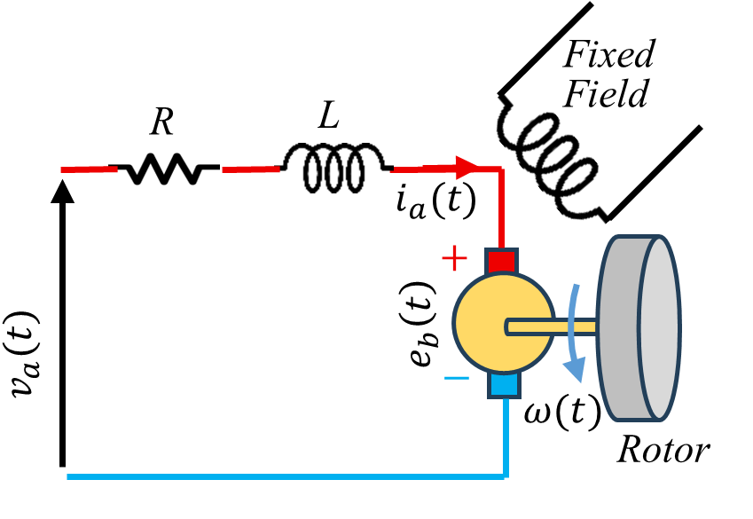
Electrical circuit for the PMDC motor consists of an armature coil where the voltage source  is applied to its terminals. The armature equivalent circuit can be represented as an inductor connected in series with a resistor and a back electromotive force (Back EMF
  ) as shown in Figure 1. The back EMF is generated during the motor rotation and directly proportional to its rotation speed
  , as in the following equation:
| 
| (1) |
By applying Kirchhoff's voltage law to the armature circuit shown in Figure 1, the following equations can be derived
| 
| (2) |
Combining Eq. (1) and Eq. (2), the electrical equation becomes [49]:
| 
| (3) |
Figure 1. PMDC motor schematic drawing
Mechanical Equation (Rotor Dynamics)
The rotor torque equation is obtained by applying Newton-Euler as in the following:
| 
| (4) |
where  is the electromagnetic torque, and
  is the load (torque) or external applied torque in N.m unit. The torque produced is direct proportional to the armature current, i.e.:
| 
| (5) |
then the rotor torque equation becomes [50]:
| 
| (6) |
State Space Representation of the System
Let the state variable be:
| 
| (7) |
| 
| (8) |
then
| 
| (9) |
| 
| (10) |
and using matrix notation,
| 
| (11) |
| 
| (12) |
then by using the numerical values in Table 1 and after a proper unit conversion, the numerical matrix representation of the state space model is:
| 
| (13) |
| 
| (14) |
where the applied voltage is in volt, the external torque is in N.m, and the motor speed is in rad/s.
CONTROL METHODOLOGY
In this study, a combined control structure is designed for PMDC motor speed control, consisting of a PI based controller and a NDOB for the purpose of minimizing the disturbance effects.
Proportional Integral (PI) Speed Controller
A classical PI controller is used to control the angular speed of a DC motor. The controller generates an armature voltage signal based on the speed error  which is defined as the difference between the desired
  and the actual measured angular speed of the motor. The control law of the PI controller is:
| 
| (15) |
For the best tuned parameters, the controller will ensure stable system operation, zero steady-state error, and correct dynamics of the speed response under nominal conditions as it will be shown in the test section in the paper.
Nonlinear Disturbance Observer (NDOB)
In practical applications of DC motors, an accurate mathematical model of the object is difficult to obtain due to the presence of unknown mechanical loads, parameter changes, and unmodeled dynamic effects. The NDOB enhances robustness by estimating the disturbance and compensating it directly in the control input. It is used to estimate the total disturbance acting on the system based on the difference between the actual system dynamics and its nominal model. The NDOB concept compares the error between the measured derivatives of the state signals and their values derived from the mathematical model.
From (6), the mechanical model is written as:
| 
| (16) |
where  represents the external applied disturbances
Based on this, the concept of a complex disturbance  is introduced, defined as the difference between the actual dynamics of the system and its nominal form:
| 
| (17) |
In the ideal case, with precisely known model parameters, the disturbance is directly related to the torque load:
| 
| (18) |
However, it should be emphasized that in the general case is a combined disturbance, including not only the load moment but also the influence of parameter uncertainty and unmodeled dynamics.
Direct determination of the signal requires differentiation of the angular velocity, which in practice leads to amplification of measurement noise. A first order low pass filter (LPF) is used as a common and practical choice in disturbance observer design due to its simplicity and sufficient attenuation of high frequency noise,
| 
| (19) |
where  is the cutoff frequency for the low pass filter.
It is worth mentioning that although the disturbance derivation is presented in the time domain, the filter design is expressed in the Laplace domain to analyze frequency characteristics and bandwidth selection.
The cutoff frequency is selected through simulation to balance disturbance tracking capability and noise attenuation. After substituting the PMDC motor parameter values, the numerical form of the observer is obtained as:
| 
| (20) |
Now, the estimated disturbance  has dimensions of angular acceleration
  while the control signal generated by the PI controller is expressed in volts. Therefore, it is necessary to apply an appropriate scaling that transforms the estimated disturbance into an equivalent voltage. Based on the physical parameters of the motor, the scaling gain
  is defined as:
| 
| (21) |
By substituting the numerical value of the motor parameters, 
The final control law therefore takes the form:
| 
| (22) |
This form of the control signal ensures dimensional matching and enables effective compensation of the effects of disturbances without excessively increasing the PI controller gains. This structure allows the PI controller to regulate nominal system, while the disturbance compensation term  actively cancels estimated disturbances.
In this work, the load torque represents a physical mechanical disturbance acting on the motor shaft. In contrast, the term denotes an overall disturbance, defined as the mismatch between the actual system dynamics and the nominal model. While the load torque contributes to , the latter also includes the effects of parameter uncertainties and unmodeled dynamics.
For digital implementation, the continuous time NDOB structure can be discretized using Tustin or zero order hold approximation. The first order LPF attenuates high frequency measurement noise and quantization effects. Furthermore, the observer bandwidth is selected to prevent amplification of sensor quantization noise making the proposed structure suitable for microcontroller implementation.
CONTROLLER PARAMETERS TUNING
The controller requires the selection of three parameters, namely: Proportional gain  , Integral gain
  , and the filter cutoff frequency .
Because there is a coupling between the parameters, and the parameter space is nonlinear and multidimensional, classical tuning methods can lead to suboptimal results. Therefore, the Arctic Puffin optimization (APO) algorithm is used in this work, since it is well suited to nonlinear and global optimization problems [51].
Arctic Puffin Optimization (APO) Algorithm
APO is novel population based metaheuristic algorithm that balances exploration and exploitation during optimization, enabling effective search of nonlinear parameter spaces. It is inspired by the hunting and movement behavior of the Arctic puffin bird in the northern seas. This method finds good solutions to complex optimization problems [51]. APO has been successfully applied in multi-objective controller tuning and engineering optimization problems, showing competitive performance compared to other metaheuristic techniques [52][53]. APO basically operates in two modes: Flight/wide search mode (individuals roam the area), and Dive/capture mode (individuals search deeper and examine the best candidates) [51]. The algorithm's power lies in deriving collective intelligence from simple rules of movement. APO has been tested in engineering applications, and improved versions have been released in some studies [52]–[56].
In APO, the position of each individual is denoted by  . The aim is to minimize the fitness function
  . Simple and general update format (schematic):
| 
| (23) |
 is a random term indicating the exploration direction (medium/far search),
  is a term indicating the direction of exploitation (approaching the best individuals),
  are weight/scale parameters.
To give a more concrete example, the following terms are generally used [51]:
| 
| (24) |
| 
| (25) |
where  are random scalars, is dimensional random vector, and
  the best solution found so far.
The algorithm for the APO algorithm is:
- Initialize: population
 Generate randomly.
 - Calculate fitness for each individual:

- Select the best individual:
- For each individual: Determine the decision to explore or dive.
- Update the position: in the form of (1), (2) and (3).
- Perform boundary check and calculate new fitness.
- Return to 3 if not a stopping condition.
These steps which explain the APO pseudo code are shown as a flowchart in Figure 2. In refinement and hybrid methods, additional strategies are added to the steps (e.g., counter-learning, DE operators) [55],[57].
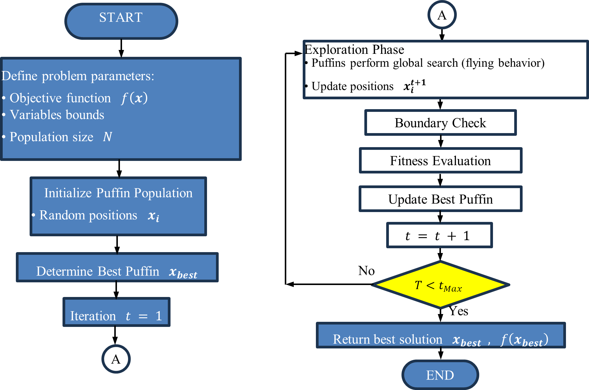
Figure 2. APO algorithm flow chart
Optimization Function and Tuning Results
The cost function for the optimization approach considering both time domain performance and the control signal effort is adopted in tuning the controller parameters. The proportional and integral gains of the PI controller and the filter cutoff frequency in the NDOB structure are optimized using the APO algorithm. In the optimization process, the population size was chosen as 20, and the maximum number of iterations as 25. These values were selected to ensure stable convergence while maintaining reasonable computational cost. The objective function was defined as follows:
| 
| (26) |
where ITAE is the integral of time multiplied by absolute error and ISCE is the integral of the square of control efforts. The mathematical representation of these functions is [58]:
| 
| (27) |
| 
| (28) |
where  is the control signal,
  is the simulation time, and
  is a weighting factor that adjusts the relative importance of control effort versus tracking performance. The selected weight factor was chosen to achieve a balanced adjustment between system response speed, stability, and actuator limits.
The optimization was run under nominal system parameters without applying any external load disturbance or parameter variations. It was performed under a reference speed of 100 rad/s over a simulation interval of 1.5 s.
The convergence action of the APO algorithm against iteration count is given in Figure 3. The figure shows a fast convergence of the cost function, denoting superior optimization behavior and a stable convergance toward the final optimal parameters. The controller parameters obtained after completing the optimization process are as follows:
Proportional gain  , Integral gain
  , Filter cutoff frequency
Repeated runs of the APO with different initials confirmed continuous convergence to nearly identical final cost values, and this is another proof of stable optimization behaviour.
A step reference velocity of 100 rad/s is applied to the nominal system with the optimized parameters and the resulting step response is shown in Figure 4. It is observed that the system exhibited a very fast and smooth transient response behaviour.
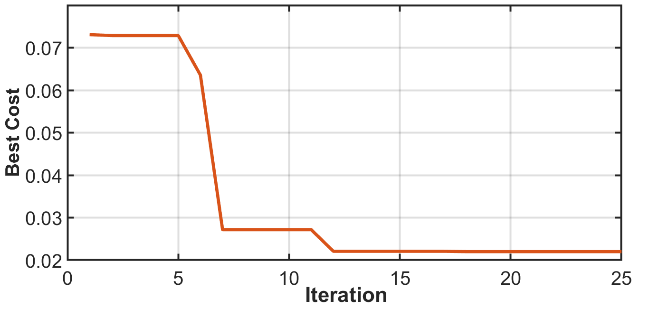
Figure 3. APO algorithm cost function versus iterations
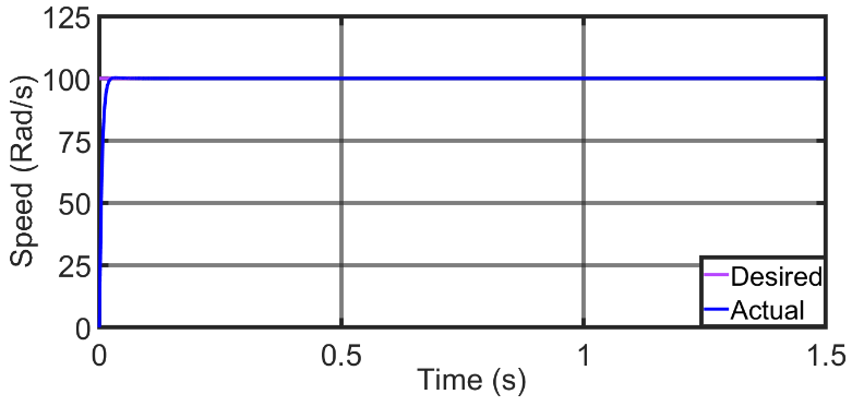
Figure 4. Step response for  .
.
The performance indicators obtained for this test are given in Table 2. The performance of the controller is evaluated using several standard indices. The Integral of Squared Error (ISE) measures the total accumulated squared tracking error over simulation time and is calculated using the following equation:
| 
| (29) |
where is the speed tracking error and is the simulation time interval.
The ISE is a measure of the tracking accuracy, so smaller ISE value indicates better overall tracking accuracy. The ITAE gives more weight to errors that continue for a longer time, which in turn helps evaluate settles speed of the system. Settling time and overshoot give an indication of how fast and smooth the motor speed settles. Overall, these measures provide a clear and complete evaluation of the speed control performance.
Table 2. Performance indices for  step input over a simulation interval of 1.5 s.
Index | Value |
Settling time (s) | 0.019 |
% Overshoot | 0.44 % |
ITAE | 0.003172 |
ISE | 32.16 |
ISCE | 18.16 |
CONTROLLER ROBUSTNESS TEST
In this section, thorough tests were carried out on the PMDC motor to examine the controller's robustness against different types of disturbances and parameter uncertainties. The system's responses to sudden load changes, periodic disturbances, and motor parameter variations are analyzed in detail. System performance improvement is evaluated relative to the conventional PI controller under identical test conditions, serving as a baseline benchmark. All the tests were run over a simulation interval of 0.5 s with a desired PMDC motor speed of 100 rad/sec.
Performance Under Step Type Disturbance
To evaluate the controller's disturbance suppression ability, a step load moment of  is applied to the system at
  . For comparison, the PI controller and PI + NDOB structures were evaluated together. Figure 5 illustrates the response under step load disturbance. The PI+NDOB controller recovers faster and exhibits reduced disturbance amplitude compared to PI. and the obtained performance indices are summarized in the Table 3. The results clearly show that the disturbing effect is significantly suppressed by adding NDOB to the system. The results indicate that the system responds to the disturbance faster and the error is corrected in a shorter time.
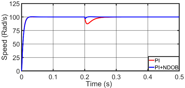
Figure 5. System response to step disturbance
Table 3. Closed loop performance indices under step disturbance.
Index | PI | PI+NDOB |
ITAE | 0.07488 | 0.008562 |
ISE | 34.94 | 31.79 |
ISCE | 11.71 | 11.83 |
Performance Under Periodic Disturbance
In the next stage, the behavior of the system under periodic disturbances is investigated. For this purpose, a sinusoidal load moment with an amplitude of  (peak to peak) at an angular frequency of
  is applied. Figure 6 presents the speed response under sinusoidal load disturbance. Compared to the conventional PI controller, the PI+NDOB structure significantly reduces the disturbance effect and lessen the tracking ripple. The performance metrics obtained from this test are presented in Table 4. It is observed that the PI controller cannot sufficiently suppress speed fluctuations under sinusoidal disturbance, whereas the NDOB play an important role in helping the PI controller dampens the disturbance effect. These results show that the proposed control structure is effective against constant and also against time variable disturbances.
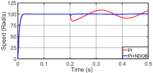
Figure 6. System response to sine wave disturbance
Table 4. Closed loop performance indices under sine wave disturbance
Index | PI | PI+NDOB |
ITAE | 0.6358 | 0.03259 |
ISE | 48.37 | 31.81 |
ISCE | 25.91 | 26.35 |
Performance Under Model Parameter Variations
Finally, the controller's robustness against uncertainties in system parameters is evaluated. Key motor parameters were perturbed within ±30% of their nominal values. This range was selected as a stress test to represent a mixed effects of modeling uncertainty, parameter mismatch, and aging effects. The motor parameters were shifted from their nominals as shown in Table 5. The speed responses obtained under these conditions are shown in Figure 7, while the performance metrics are given in Table 6. Even with modified motor parameters, the PI+NDOB controller maintains stable operation and achieves faster recovery compared to the conventional PI controller. The results demonstrate that under parameter uncertainties, the NDOB based PI controller improves both transient and steady state performance. The reduction in settlement time and other indices indicates that the proposed structure is more robust against model errors.
Table 5. Parameter variation test settings
Parameter | Percentage variation |
| +10% |
| +5% |
| -5% |
| +30% |
| +20% |
| -10% |
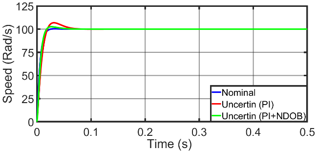
Figure 7. System response under model parameter variations
Table 6. Closed loop performance indices under parameter uncertainties
Index | Nominal system | Perturbed System |
PI | PI+NDOB |
Settling time (s) | 0.019 | 0.057 | 0.036 |
% Overshoot | 0.44 | 6.93% | 2.63% |
ITAE | 0.003172 | 0.01169 | 0.005053 |
ISE | 31.76 | 45.59 | 36.97 |
ISCE | 6.327 | 6.167 | 6.301 |
Sensor Noise Effect Analysis
To study the effect of the measurement noise on the proposed controller performance, white Gaussian noise was added to the measured motor speed signal in the simulation environment. The noise sampling frequency was set to 10 kHz to represent high frequency sensor noise typically present in PWM based motor drive systems. This test aims to examine the impact of noisy measurements of the NDOB, which is a known practical concern in observer dependent control systems.
Figure 8 shows the speed response under measurement noise effect. Although the speed signal exhibits small fluctuations due to injected noise, the PI+NDOB controller maintains stable tracking performance. The presence of the first order LPF in the observer structure effectively attenuates high frequency noise components.
The performance indices under sensor noise conditions are represented in Table 7. The ITAE, and ISE, values for PI and PI+NDOB controllers are almost identical, indicating that the proposed nonlinear observer does not degrade tracking accuracy in the presence of measurement noise. A slight increase is observed in ISCE, which reflects a marginal higher control efforts. Overall, these results show that NDOB does not amplify noise into excessive control effort.
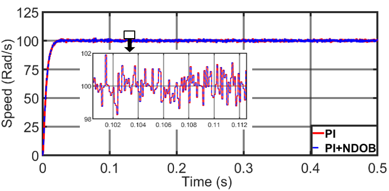
Figure 8. System response under measurement noise
Table 7. Closed loop performance indices under measurement noise
Index | PI | PI+NDOB |
ITAE | 0.07351 | 0.07352 |
ISE | 32.49 | 32.48 |
ISCE | 6.327 | 6.35 |
Discussion
The simulation results show that integrating the NDOB with the classical PI controller led to an improvement in transient response and disturbance rejection under step disturbance, sinusoidal disturbance, and parameter uncertainty tests. The significant decreases in ITAE and settling time compared to PI control demonstrate the improvement in tracking accuracy and robustness.
The improved performance is due to the NDOB’s ability to estimate and compensate the disturbances in real time. This structure maintains low computational complexity while achieving robust performance, so it will be suitable for embedded motor drive applications.
It is worth to mention that the improved disturbance rejection is at a cost of a slight increase in the control effort index (ISCE), typically within 1–2% compared to the efforts applied by the conventional PI controller. This small increase is caused by the additional compensation action applied by the NDOB. However, this minor increase does not lead to actuator saturation, chattering, or instability. Therefore, the improvement in the ITAE and transient respponse specifications is achieved with only small increase in control energy, representing a favorable trade off between robustness and control effort.
CONCLUSION
In this study, a new control method for speed control of PMDC motors has been developed. The proposed control structure combines the simplicity of a PI controller with a NDOB to better suppress external disturbances and model uncertainties. The proposed controller structure compromise between structural simplicity and robust disturbance rejection ability. The proposed controller and the observer parameters were optimally tuned offline using the APO algorithm. The cost function used through the tuning leads to an effective trade-off between system response speed, disturbance suppression ability, and control effort. The controller attained 94.9%, 88.6% reduction in ITAE under step and sinusoidal disturbances respectively. These achevement demonstrating significant performance enhancement over conventional PI control. Simulation tests demonstrated that the new approach reduces the effect of external torque disturbances and changes in motor parameters.
Although the proposed structure enhances motor performance and robustness, it introduces additional lightweight computational demand compared to conventional PI control. However, the observer formulation remains suitable for real time implementation since the APO parameter tuning is performed offline. In conclusion, this study presents a low-complexity and a high-performance control structure, that makes it suitable for embedded industrial applications. Future work will focus on experimental validation of the proposed controller using real hardware platforms.
DECLARATION
Supplementary Materials
Not Applicable.
Sustainable Development Goals
Not Applicable.
Author Contribution
Not Applicable (Single Author).
Funding
This research received no external funding.
Acknowledgement
Not Applicable.
Conflicts of Interest
The authors declare no conflict of interest.
ABBREVIATIONS
The following abbreviations are used in this manuscript.
PMDC | : | Permanent Magnet Direct Current. |
PI | : | Proportional Integral |
NDOB | : | Nonlinear Disturbance observer |
APO | : | Arctic Puffin Optimization |
PID | : | Proportional Integral Derivative |
SMC | : | Sliding Mode Control |
ADRC | : | Active Disturbance Rejection Control |
ESO | : | Extended State Observer |
NLESO | : | Nonlinear Extended State Observer |
LQR | : | Linear Quadratic Regulator |
EMF | : | Electromotive Force |
ITAE | : | Integral Time of Absolute Error |
ISCE | : | Integral of Squared Control Effort |
ISE | : | Integral of Squared Error |
REFERENCES
- M. F. Fazdi and P.-W. Hsueh, “Parameters Identification of a Permanent Magnet DC Motor: A Review,” Electronics, vol. 12, no. 12, p. 2559, 2023, https://doi.org/10.3390/electronics12122559.
- M. Salah and M. Abdelati, “Parameters Identification of a Permanent Magnet DC Motor,” The Islamic University of Gaza, vol. 94. 2009, https://doi.org/10.2316/p.2010.675-085.
- A. J. Humaidi and I. Kasim Ibraheem, “Speed Control of Permanent Magnet DC Motor with Friction and Measurement Noise Using Novel Nonlinear Extended State Observer-Based Anti-Disturbance Control,” Energies, vol. 12, no. 9, p. 1651, 2019, https://doi.org/10.3390/en12091651.
- D. Somwanshi, M. Bundele, G. Kumar, and G. Parashar, “Comparison of fuzzy-PID and PID controller for speed control of DC motor using LabVIEW,” Procedia Computer Science, vol. 152, pp. 252-260, 2019, https://doi.org/10.1016/j.procs.2019.05.019.
- O. O. A. Mohammed and Dr. A. Taifor Ali, “Comparative Study of PID and Fuzzy Controllers for Speed Control of DC Motor,” International Journal of Innovative Research in Science, Engineering and Technology, vol. 03, no. 09, pp. 16104–16110, 2014, https://doi.org/10.15680/ijirset.2014.0309045.
- P. Vikhe, N. Punjabi, and C. Kadu, “Real Time DC Motor Speed Control using PID Controller in LabVIEW,” International Journal of Advanced Research in Electrical, Electronics and Instrumentation Engineering, vol. 03, no. 09, pp. 12162–12167, 2014, https://doi.org/10.15662/ijareeie.2014.0309046.
- V. Rajs, N. Lj. Rašević, M. Z. Bodić, M. M. Zuković, and K. B. Babković, “PID Controller Design for Motor Speed Regulation with Linear and Non-Linear Load,” IFAC-Papers, vol. 55, no. 4, pp. 225–229, 2022, https://doi.org/10.1016/j.ifacol.2022.06.037.
- D. K. Shary and H. J. Nekad, “Position and Speed Control for Permanent Magnet DC Motor Based on Different Optimization Algorithms,” Journal Européen des Systèmes Automatisés, vol. 57, no. 06, pp. 1705–1711, 2024, https://doi.org/10.18280/jesa.570618.
- T. Atyia and S. Abdullah, “Genetic Algorithm of tuning PID for Controlling Speed of DC Motor,” NTU Journal of Renewable Energy, vol. 9, no. 1, pp. 38–47, 2025, https://doi.org/10.56286/7ta6z241.
- M.A.R. Ismail and E.M. Heessain, “Speed Control of PMDC Motor using PID Controller,” International Journal of Science and Research (IJSR), vol. 5, no. 5, 2016, https://doi.org/10.21275/v5i5.nov163972.
- D. Saputra, A. Ma'arif, H. Maghfiroh, P. Chotikunnan, and S. N. Rahmadhia, “Design and application of PLC-based speed control for DC motor using PID with identification system and MATLAB tuner,” International Journal of Robotics and Control Systems, vol. 3, no. 2, pp. 233-244, 2023, https://doi.org/10.31763/ijrcs.v3i2.775.
- V. Sankardoss and P. Geethanjali, “Parameter estimation and speed control of a PMDC motor used in wheelchair,” in Energy Procedia, vol. 117, pp. 345-352, 2017, https://doi.org/10.1016/j.egypro.2017.05.142.
- A. Alkamachi, “Permanent magnet dc motor (pmdc) model identification and controller design,” Journal of Electrical Engineering, vol. 70, no. 4, 2019, https://doi.org/10.2478/jee-2019-0060.
- K. G. Abdulhussein, N. M. Yasin, and I. J. Hasan, “Comparison between butterfly optimization algorithm and particle swarm optimization for tuning cascade pid control system of pmdc motor,” International Journal of Power Electronics and Drive Systems, vol. 12, no. 2, 2021, https://doi.org/10.11591/ijpeds.v12.i2.pp736-744.
- N. Bayhan and Y. Koçak, “A Comparative Study of Discretization Methods for Model Predictive Current Control of Permanent Magnet Synchronous Motors,” Processes, vol. 14, no. 1, p. 14, 2025, https://doi.org/10.3390/pr14010014.
- A. A. Hassan, N. K. Al-Shamaa, and K. K. Abdalla, “Comparative Study for DC Motor Speed Control Using PID Controller,” International Journal of Engineering and Technology, vol. 9, no. 6, 2017, https://doi.org/10.21817/ijet/2017/v9i6/170906069.
- R. SHEIKH DEBES and T. KARA, “Design and Simulation of a PID Neural Network Controller for PMDC Motor Speed and Position Control,” European Journal of Science and Technology, 2022, https://doi.org/10.31590/ejosat.1222247.
- T. Prasoetphon, K. Selamassakul, T. Sittiwanchai and W. Jitviriya, "Fuzzy-PID vs. PID Controllers: A Comparative Study on DC Motor Speed Control," 2024 1st International Conference on Robotics, Engineering, Science, and Technology (RESTCON), pp. 64-68, 2024, https://doi.org/10.1109/RESTCON60981.2024.10463588.
- K. A. K. KHALAF and M. Teke, “Controlling the operation of the dc motor by using pid with metaheuristic technology,” Journal of Computer & Electrical and Electronics Engineering Sciences, vol. 1, no. 2, 2023, https://doi.org/10.51271/jceees-0008.
- M. M. A. Rahman, M. Aryal and R. Amatya, "Speed Control of DC Motors Using an Artificial Neural Network (ANN)," 2024 IEEE International Conference on Electro Information Technology (eIT), pp. 333-336, 2024, https://doi.org/10.1109/eIT60633.2024.10609891.
- A. Maarif and N. R. Setiawan, “Control of dc motor using integral state feedback and comparison with pid: Simulation and arduino implementation,” Journal of Robotics and Control (JRC), vol. 2, no. 5, 2021, https://doi.org/10.18196/jrc.25122.
- P. Dhinakaran and D. Manamalli, “Novel strategies in the Model-based Optimization and Control of Permanent Magnet DC motors,” Computers and Electrical Engineering, vol. 44, 2015, https://doi.org/10.1016/j.compeleceng.2015.04.002.
- H H. Chu, W. Tao, B. Gao, Q. Liu and H. Chen, "Speed control of the permanent-magnet DC motor subjected to uncertainty and disturbance," 2016 35th Chinese Control Conference (CCC), pp. 4664-4669, 2016. https://doi.org/10.1109/ChiCC.2016.7554076.
- L. J. Rashad, “Speed Control of Permanent Magnet D.C. Motor Using Neural Network Control,” Engineering and Technology Journal, vol. 28, no. 19, 2010, https://doi.org/10.30684/etj.28.19.4.
- Y. Zhang, S. Li, X. Luo and M. -s. Shang, "A dynamic neural controller for adaptive optimal control of permanent magnet DC motors," 2017 International Joint Conference on Neural Networks (IJCNN), pp. 839-844, 2017, https://doi.org/10.1109/IJCNN.2017.7965939.
- R. Challoo, R. Palaniswamy, S. Li, and S. Ozcelik, “Adaptive Neural Controller for a Permanent Magnet DC Motor,” in Intelligent Engineering Systems through Artificial Neural Networks, 2009. https://doi.org/10.1115/1.802953.paper63.
- A. Sardashti and J. Nazari, “A learning-based approach to fault detection and fault-tolerant control of permanent magnet DC motors,” Journal of Engineering and Applied Science, vol. 70, no. 1, 2023, https://doi.org/10.1186/s44147-023-00279-5.
- Hayder Salim Hameed, “Performance Trade-Offs in AI-Based Speed Control of PMDC Motors: A Comparative Study of Fuzzy Logic and Neural Network Controllers,” Proceedings of Engineering and Technology Innovation, vol. 31, 2025, https://doi.org/10.46604/peti.2025.15024.
- M. Tuna, C. B. Fidan, S. Kocabey, and S. Görgülü, “Effective and reliable speed control of permanent magnet DC (PMDC) motor under variable loads,” Journal of Electrical Engineering and Technology, vol. 10, no. 5, 2015, https://doi.org/10.5370/JEET.2015.10.5.2170.
- Z. Tir, O. Malik, M. A. Hamida, H. Cherif, Y. Bekakra and A. Kadrine, "Implementation of a fuzzy logic speed controller for a permanent magnet dc motor using a low-cost Arduino platform," 2017 5th International Conference on Electrical Engineering - Boumerdes (ICEE-B), pp. 1-4, 2017. https://doi.org/10.1109/ICEE-B.2017.8192218.
- R. Shenbagalakshmi, S. K. Mittal, J. Subramaniyan, V. Vengatesan, D. Manikandan, and K. Ramaswamy, “Adaptive speed control of BLDC motors for enhanced electric vehicle performance using fuzzy logic,” Scientific Reports, vol. 15, no. 1, p. 12579, 2025, https://doi.org/10.1038/s41598-025-90957-6.
- M. K. Kaloi, “Fuzzy-PID based control scheme for PMDC series motor speed control,” Indian J. Sci. Technol., vol. 13, no. 28, 2020, https://doi.org/10.17485/ijst/v13i28.653.
- E. Çelik, G. Bal, N. Öztürk, E. Bekiroglu, E. H. Houssein, C. Ocak, and G. Sharma, “Improving speed control characteristics of PMDC motor drives using nonlinear PI control,” Neural Computing and Applications, vol. 36, no. 16, pp. 9113-9124, 2024, https://doi.org/10.1007/s00521-024-09568-3.
- H. Velasco-Muñoz, J. E. Candelo-Becerra, F. E. Hoyos, and A. Rincón, “Speed Regulation of a Permanent Magnet DC Motor with Sliding Mode Control Based on Washout Filter,” Symmetry (Basel)., vol. 14, no. 4, 2022, https://doi.org/10.3390/sym14040728.
- A. K. Mohammed, N. K. Al-Shamaa and A. Q. Al-Dujaili, "Super-Twisting Sliding Mode Control of Permanent Magnet DC Motor," 2022 IEEE 18th International Colloquium on Signal Processing & Applications (CSPA), pp. 347-352, 2022, https://doi.org/10.1109/CSPA55076.2022.9782029.
- A. K. Mohammed, N. K. Al-Shamaa, and A. Q. Al-Dujaili, “Sliding mode control of the permanent magnet DC motor based on optimal control design,” in AIP Conference Proceedings, vol. 2804, no. 1, p. 030002, 2023, https://doi.org/10.1063/5.0154543.
- A. -M. M. A. Mohamed, "Sliding mode control design and application to permanent magnet dc motor speed control," 2006 Eleventh International Middle East Power Systems Conference, pp. 25-29, 2006, https://ieeexplore.ieee.org/abstract/document/5372391.
- W. Riyadh and I. Kasim, “Improved Sliding Mode Nonlinear Extended State Observer based Active Disturbance Rejection Control for Uncertain Systems with Unknown Total Disturbance,” International Journal of Advanced Computer Science and Applications, vol. 7, no. 12, 2016, https://doi.org/10.14569/ijacsa.2016.071211.
- P. Venktareddy, P. Narayanappa Anand, and P. Pundareekane Kanchappa, “PID Gain Tuning for Robust Control of PMDC Motor for External Disturbance Rejection with Constrained Motor Parameter Variations through H∞,” in Production Engineering and Robust Control, 2022. https://doi.org/10.5772/intechopen.102546.
- H. S and A. R. S, "Multithreaded State Feedback Control with Speed Estimation for Permanent Magnet DC Motor Speed Control," 2024 IEEE Recent Advances in Intelligent Computational Systems (RAICS), pp. 1-6, 2024. https://doi.org/10.1109/RAICS61201.2024.10689797.
- J. Yao, Z. Jiao, and D. Ma, “Adaptive robust control of dc motors with extended state observer,” IEEE Transactions on Industrial Electronics, vol. 61, no. 7, 2014, https://doi.org/10.1109/TIE.2013.2281165.
- R. M. Brisilla, V. Sankaranarayanan and Joseph Godfrey A., "Extended state observer based sliding mode control of permanent magnet DC motor," 2015 Annual IEEE India Conference (INDICON), pp. 1-6, 2015, https://doi.org/10.1109/INDICON.2015.7443441.
- A. R. S and H. S, "Speed Sensor-less Power Hardware In the Loop Emulation of PMDC Machine with Fuzzy Based Observer," 2024 IEEE International Conference on Power Electronics, Drives and Energy Systems (PEDES), pp. 1-6, 2024, https://doi.org/10.1109/PEDES61459.2024.10961090.
- S. Srivastava and V. S. Pandit, "A scheme to control the speed of a DC motor with time delay using LQR-PID controller," 2015 International Conference on Industrial Instrumentation and Control (ICIC), pp. 294-299, 2015, https://doi.org/10.1109/IIC.2015.7150756.
- Muhammad Izzul Haj, Dimas Eka Saputra, Rama Arya Sobhita, and Anggara Trisna Nugraha, “Simulation of Motor Speed Regulation Utilizing PID and LQR Control Techniques,” Journal of Marine Electricaland IndustrialTechnology, vol. 2, no. 1, pp. 41-49,2025, https://doi.org/10.35991/mein.v2i1.37.
- L. Thamir, “Optimal Tuning of Linear Quadratic Regulator Controller Using Ant Colony Optimization Algorithm for Position Control of a Permanent Magnet DC Motor,” Iraqi Journal of Computer, Communication, Control and System Engineering, vol. 20, no. 3, 2020, https://doi.org/10.33103/uot.ijccce.20.3.3.
- O. Saleem and K. Mahmood-Ul-Hasan, “Adaptive collaborative speed control of PMDC motor using hyperbolic secant functions and particle swarm optimization,” Turkish Journal of Electrical Engineering and Computer Sciences, vol. 26, no. 3, 2018, https://doi.org/10.3906/elk-1709-54.
- M. R. Çorapsız, “Comparison of Parameter Estimation Techniques for Control Parameter Identification of Permanent Magnet Direct Current Motor Speed Control,” Advanced Control for Applications: Engineering and Industrial Systems, vol. 7, no. 1, 2025, https://doi.org/10.1002/adc2.70005.
- I. S. Kareem, S. R. Al-Sakini, and G. A. Bilal, “OPTIMAL SPEED AND POSITION CONTROLLER FOR PMDC MOTOR BASED GWO ALGORITHM,” Kufa Journal of Engineering, vol. 16, no. 3, 2025, https://doi.org/10.30572/2018/KJE/160310.
- A. G. Abdullah, M. A. Ibrahim, and A. S. Saleh, “Performance Enhancing Speed Control of a DC Motor Based on an Artificial Neural Network,” Journal Europeen des Systemes Automatises, vol. 57, no. 5, 2024, https://doi.org/10.18280/jesa.570524.
- W. chuan Wang, W. can Tian, D. mei Xu, and H. fei Zang, “Arctic puffin optimization: A bio-inspired metaheuristic algorithm for solving engineering design optimization,” Advances in Engineering Software, vol. 195, 2024, https://doi.org/10.1016/j.advengsoft.2024.103694.
- P. Sharma and S. Raju, “Parameter estimation of PEM fuel cell by using Enhanced Arctic Puffin Optimization algorithm,” Ionics (Kiel)., vol. 31, no. 9, 2025, https://doi.org/10.1007/s11581-025-06390-2.
- A. T. Tran, M. P. Duong, P. Truong, J. W. Shim, and C. P. Lim, “An improved arctic puffin optimization-based multi-objective approach with novel cascade dual FOPID control for frequency regulation in standalone microgrids,” Energy Reports, vol. 14, 2025, https://doi.org/10.1016/j.egyr.2025.11.046.
- Y. Zhu, T. Wang, and N. Zhao, “Arctic Puffin Optimization Algorithm Integrating Opposition-Based Learning and Differential Evolution with Engineering Applications,” Biomimetics, vol. 10, no. 11, 2025, https://doi.org/10.3390/biomimetics10110767.
- H. N. Fakhouri, M. S. Alkhalaileh, F. Hamad, N. N. Sirhan, and S. N. Fakhouri, “Hybrid Arctic Puffin Algorithm for Solving Design Optimization Problems,” Algorithms, vol. 17, no. 12, 2024, https://doi.org/10.3390/a17120589.
- A. Banerjee, S. K. Chakraborty, and A. S. Parihar, “Adaptive 3D trajectory planning for UAV swarms: An Arctic puffin optimization-based mobility model,” Physical Communication, vol. 73, 2025, https://doi.org/10.1016/j.phycom.2025.102865.
- Y. Su and W. Jiang, “Path Planning Based on the Improved Arctic Puffin Algorithm,” in Proceedings of 2025 5th International Conference on Control and Intelligent Robotics, ICCIR 2025, pp. 136-140, 2025. https://doi.org/10.1145/3757940.3757962.
- A. Omer Shuaib and M. Mohamed Ahmed, “Robust PID Control System Design Using ITAE Performance Index (DC Motor Model),” Int. J. Innov. Res. Sci. Eng. Technol., vol. 03, no. 08, 2014, https://doi.org/10.15680/ijirset.2014.0308002.
Ahmed Alkamachi (Robust Speed Control of Permanent Magnet DC Motors Using an Arctic Puffin Optimized PI Controller and Nonlinear Disturbance Observer)