ISSN: 2685-9572 Buletin Ilmiah Sarjana Teknik Elektro
Vol. 8, No. 4, August 2026, pp. 1087-1106
Crocodile Optimizer-Based DC Chopper Control for Voltage Dip and Swell Mitigation in PMSG-Based WT
Basiony Shehata Atia 1, Fajer M. Alelaj 2, Mohamed Metwally Mahmoud 3,4,5, Alfian Ma’arif 6,
Abdel-Magid M Ali 1
1 Department of Electrical Engineering, Faculty of Engineering, Aswan University, Aswan, Egypt
2 Water Research Center, Kuwait Institute for Scientific Research, Kuwait
3 Electrical Engineering Department, Faculty of Energy Engineering, Aswan University, Aswan, Egypt
4 Jadara University Research Center, Jadara University, P.O Box 733, Irbid, Jordan
5 ENET Centre, CEET, VSB—Technical University of Ostrava, Ostrava, Czech Republic
6 Department of Electrical Engineering, Universitas Ahmad Dahlan, Yogyakarta, Indonesia
ARTICLE INFORMATION |
| ABSTRACT |
Article History: Received 28 November 2025 Revised 11 June 2026 Accepted 06 August 2026 |
| 
The increasing penetration of wind energy systems requires advanced control strategies capable of maintaining stable operation during grid disturbances while complying with modern GC requirements. This paper proposes a COA-based control scheme for a DC chopper integrated into a PMSWG system to enhance its FRTC under severe voltage disturbances. The COA is employed to optimally tune the controller parameters, ensuring effective regulation of the DC-link voltage and improved transient performance. The proposed approach is evaluated under four critical grid conditions, including three voltage dip scenarios corresponding to 100%, 80%, and 40% retained voltage levels, as well as a 20% voltage swell condition. Simulation results demonstrate that the proposed controller maintains the DC-link voltage close to its reference value of 1150 V, preventing excessive overvoltage during fault events and reducing stress on power electronic converters. Moreover, the control strategy satisfies GC requirements by providing appropriate reactive power support during VDs while ensuring controlled active power transfer. The optimized controller effectively suppresses electromagnetic torque oscillations, limits transient current peaks in the GSC, and enables rapid recovery of generator speed following fault clearance. Comprehensive MATLAB/Simulink studies confirm that the proposed COA-based DC chopper control significantly improves system transient stability, enhances grid-support capability, and ensures reliable operation under both voltage dip and swell conditions. In addition, the improved DC-link voltage regulation contributes to increased converter lifetime and reduced operational downtime, demonstrating the practicality and effectiveness of the proposed solution for modern wind energy conversion systems. |
Keywords: Braking Chopper; DC Bus Voltage Control; Crocodile Optimizer; Sustainable Development; Unbalanced Voltages; Wind Energy |
Corresponding Author: Mohamed Metwally Mahmoud, Electrical Engineering Department, Faculty of Energy Engineering, Aswan University, Aswan 81528, Egypt. Email: metwally_m@aswu.edu.eg |
This work is open access under a Creative Commons Attribution-Share Alike 4.0 
|
Document Citation: B. S. Atia, F. M. Alelaj, M. M. Mahmoud, A. Ma’arif, and A.-M. M. Ali, “Crocodile Optimizer-Based DC Chopper Control for Voltage Dip and Swell Mitigation in PMSG-Based WT,” Buletin Ilmiah Sarjana Teknik Elektro, vol. 8, no. 4, pp. 1087-1106, 2026, DOI:10.12928/biste.v8i4.15464. |
INTRODUCTION
The current global energy demand exceeds the existing supply capacity, highlighting the urgent need for efficient and economically viable solutions to address future energy requirements [1]–[3]. In this context, prioritizing the integration of SSs has become essential in the development of modern energy systems [4][5]. Nevertheless, the global contribution of SSs to primary energy production remains inadequate to satisfy the increasing worldwide demand for energy and electricity [6][7]. Numerous developing nations are making substantial efforts to advance their energy sectors; however, achieving these objectives continues to present considerable challenges [8][9]. Energy resources are required to satisfy a wide range of human demands, including transportation, heating, and electricity supply for urban infrastructures. At the same time, assessing the long-term sustainability of these resources is of paramount importance. Sustainable sources ensure a continuous energy supply while significantly contributing to the reduction of pollution and greenhouse gas emissions, which are among the primary drivers of climate change [10][11]. SSs encompass naturally available resources such as biomass, geothermal energy, solar radiation, hydropower, wind energy, and ocean resources, all of which can be exploited to produce clean and usable energy. According to [12], each sustainable source possesses distinct advantages and limitations, which were systematically summarized in tabular form. To promote a sustainable and prosperous future, the United Nations introduced the SDGs in 2015, aiming for their comprehensive implementation by 2030 [13]. The framework of the SDGs also facilitates the monitoring and evaluation of progress toward achieving the objectives of the 2030 Agenda [14].
With respect to the SDGs, the expansion of SSs facilitates energy security across multiple sectors [15]. In addition to supporting environmental conservation and community development initiatives, SSs contribute significantly to meeting increasing energy demands. They have been recognized as an effective approach for addressing the energy challenges of the twenty-first century while simultaneously reducing negative environmental and climatic impacts [16][17]. Among renewable energy resources, wind energy provides several advantages owing to its technological maturity, reliable infrastructure, and economic feasibility [18]. Consequently, wind energy is expected to play an increasingly important role in the global energy supply in the years ahead [19][20].
With the increasing penetration of WFs into interconnected power systems, numerous countries have established specific interconnection standards and operational requirements for integrating wind farms into electrical grids, commonly referred to as GCs [21]. These GCs mandate that WFs remain connected to the power system during fault conditions and supply an adequate amount of reactive power (Q) at the PCC during VDs [22][23]. Following fault clearance, wind farms are also required to restore and deliver active power (P) in compliance with GC specifications. For instance, the Danish GC stipulates that wind farms with a rated capacity greater than 11 kW must maintain grid connectivity for up to 0.5 s during a PCC voltage dip of as much as 80%, as illustrated in Area B of (Figure 1(a)) [24]. During this fault duration, the WF is required to inject Q to support the PCC voltage, as shown in (Figure 1(b)) [25]. The capability of WFs to satisfy GC requirements depends on both the generator technology and the adopted grid integration approach. Among the currently deployed wind energy conversion systems, the PMSWG has gained considerable attention due to its favorable operational characteristics. In most applications, the PMSWG is connected to the grid through full-scale BTBCs [26]. This configuration provides several benefits, including enhanced reactive power control capability, improved MPP tracking, and superior grid-side power quality performance.
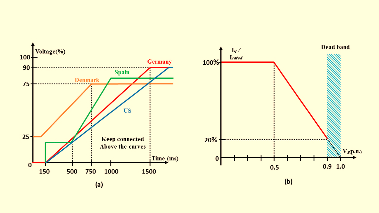
- GC necessities that consist of: (a) a ride-through curve; and (b) a support curve of Iq
During grid faults, the wind farm generator continues producing electrical power; however, the amount of power delivered to the grid decreases because of the voltage dip at the PCC and the action of the GSC current limiter [27]. As a result, the mismatch between the input and output power of the converter during grid voltage dips leads to an over-voltage condition in the DCL [28]. To enhance and ensure the FRTC of WFs, various control and protection strategies have been proposed.
These approaches can generally be classified into two primary categories: (a) the use of external auxiliary equipment, and (b) the enhancement of BTBCs and pitch angle control systems. Each approach possesses distinct advantages and limitations, which have been comprehensively discussed in [29]. A recent control strategy involving the exchange of control functions between the GSC and MSC was proposed in [27]. Although this technique eliminates the need for additional external devices to achieve FRTC and demonstrates satisfactory performance under various VD conditions, the study presented in [30] indicated that such strategies may lead to unsatisfactory operational performance in certain cases. Despite the preference for approach (b) due to its low implementation cost and operational simplicity, it requires modifications to the pitch angle control mechanisms and converter control structures. Consequently, approach (a) is widely considered a reliable and GC-compliant solution for modern WFs.
Installing a BC across the DCL of the BTBC is considered one of the simplest and most cost-effective solutions for enhancing FRTC [31]–[33]. In contrast to other approaches categorized under method (a), such as the deployment of FACTS and ESS, which are generally characterized by high complexity and implementation cost [34], the BC-based approach offers a practical and economical alternative. One of the major advantages of the BC is its capability to operate as a temporary and rapid energy dissipation unit during fault conditions, making it suitable for application in various types of wind farms. Moreover, several studies have investigated system performance with the integration of BCs, as reported in [35]–[38]. In addition to wind farm applications, BCs have also been employed in AFDs and in FRT enhancement strategies for photovoltaic systems. A comprehensive overview of BC engineering applications in both (a) WFs and (b) AFD systems was presented in [39]. Various control techniques have been proposed for BC operation and management. Section 3 of this study presents a detailed discussion of several BC control methods, together with their respective advantages and limitations.
The existing literature presents various control and management strategies for PMSWGs. For instance, during GS disturbances, the study in [40] employed a Lyapunov-based MPC approach for the regulation of BTBCs. The proposed method demonstrated an improved transient response in DCL voltage (DCLV) regulation when compared with the conventional PI controller. However, the absence of converter current limiting mechanisms makes it difficult to accurately assess system performance under severe VD conditions. In [41], an adaptive fuzzy RST control technique was implemented for the regulation of both the MSC and the GSC. Additionally, the effectiveness of employing a high-selectivity filter under asymmetrical fault conditions was investigated.
Sliding Mode Control (SMC) is considered one of the most effective control strategies for enhancing system robustness and resilience [42]. This reliable control approach enables the GSC to satisfy GC requirements by injecting Q into the power system (PS), while simultaneously maintaining the DC-link voltage (DCLV) at its nominal level and ensuring appropriate system responses under both normal and fault operating conditions. Accordingly, SMC has been widely applied for the control of wind farms during fault scenarios. In [43], a configuration consisting of two PMSWGs connected to a common DCL was proposed, where a DC–AC converter interfaces the shared DCL with the power system. In this setup, the SMC technique was employed in the design and implementation of the control systems for all converters to achieve effective FRT performance. Despite its advantages, one of the main limitations of the SMC approach is the occurrence of chattering in the voltage and current signals of the converters. To address this issue, advanced techniques such as the Super-Twisting SMC (STSMC) method and the ERL approach have been introduced [44].
The proposed controller overcomes the limitations associated with existing BC control techniques, as discussed in Section 4. It should be noted that the proposed BC regulator can be applied to any BC integrated within the DCL of a BTBC, making it fully compatible with various BTBC control strategies. Furthermore, the proposed architecture is not restricted to the GC requirements of a specific country, as it can be adapted to comply with different international GC standards. In this study, the Danish GC is adopted as the reference framework for evaluation and analysis purposes.
The remainder of this paper is organized as follows. Section 2 presents the materials and methods employed in this study, including a brief description of the PMSWG model and system configuration, a review of existing BC control techniques, and the design and implementation of the proposed reliable BC controller incorporating the COA approach. Section 3 discusses the simulation results and corresponding performance analysis. Finally, the main conclusions and findings of the study are summarized in Section 4.
MATERIALS AND METHODS
PMSWG Description & Modeling
The PMSWG model is divided into four key components (Figure 2): (1) mechanical section; (2) equivalent electric circuit in SRFMSC; (3) BTBC, DCL, BC, and the machine equations, in the SRFMSC, are shown in (1)–(6). The next equation's symbols are fully described in [45][46].
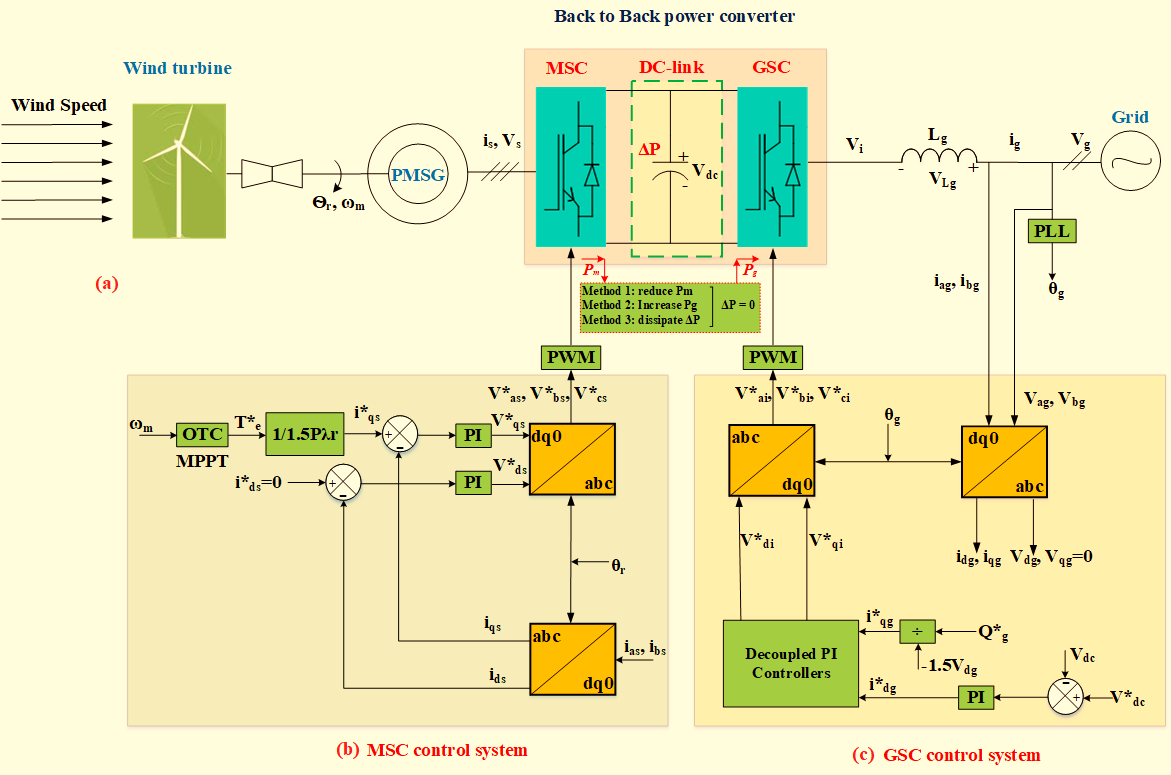
- Addressed system
The pertinent equations for the GS electrical components and the BTBC-DCL are provided in (7) and (8). The BC-P loss flexibility only happens in (7) when there is a fault. Notably, the GS (+\-sequence) electrical parts have been modeled using the well-liked SRFGSC approach [27].
| 
| (7) |
| 
| (8) |
Control Scheme of MSC
As illustrated in Figure 2(b), the MSC controller within the Synchronous Reference Frame MSC (SRFMSC) consists of two control loops operating along the dq-axes. The primary objectives of the MSC control strategy are MPPT and generator power factor regulation. To minimize power losses and avoid demagnetization of the PMSWG, the reference current for the d-axis ( ) is set to zero [24]. In addition, the OTC method is employed to achieve MPPT by generating the required q-axis current reference [35].
Control Scheme of GSC
To regulate (+\-sequence) currents, a dual current controller is implemented in the ( ), as illustrated in (Figure 2(c)). Owing to the high effectiveness of the (SRF-PLL) and the separation (+\-sequence) (I/V) components in improving the performance of the GSC control system, the sequence separation method proposed in [24] is adopted in this study. This control strategy effectively suppresses the second-order harmonic components in the DCLV and enhances the active power (P) delivered to the PS during fault conditions. In addition to regulating the DCLV, the controller also ensures appropriate Q support to the grid. Furthermore, the reference values
  and
and  are determined according to the methodology presented in [27]. The desired (+\-sequence)
  current references are calculated using (9) [47]. In each operating condition, is appropriately adjusted to achieve improved regulation of the DCLV.
| 
| (9) |
Review of BC Control Methods
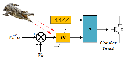
The BC primarily consists of two main components: a DC chopper switch and a resistor, as illustrated in (Figure 2(a)). When the DCLV exceeds a predefined threshold, the resistor is connected into the circuit to dissipate the excess energy stored in the DC-link, thereby maintaining the voltage within permissible operating limits. Several control strategies have been proposed for BC regulation and duty cycle (D) determination. In [41], the deviation between the measured DCLV and its reference threshold is processed through a PI controller to determine the modulation index (m), which is subsequently used to calculate the duty cycle, as shown in (Figure 3(a)) [48]. In contrast, the approach presented in [49] directly compares the DCLV with its threshold value, and the resulting signal is utilized to generate the gate pulse for the BC switch, as illustrated in (Figure 3(b)) [48]. The primary objective of these controllers is to maintain the DCLV at a constant value. Consequently, the capability of the GSC to provide Q support to the grid has not been fully utilized. Furthermore, these control methods are not sufficiently suitable for operation during VD conditions, where mitigation of system imbalance caused by the VDs is required.
Reference [50]. proposed a control strategy in which the BC is activated based on the current phasor (CP) signal of the GSC. According to this approach, during a VD, the GSC attempts to maintain the active power (P) delivered to the PS at a constant level. As a result, the occurrence of a VD leads to a significant increase in the magnitude of the current phasor injected into the PS. The authors also indicated that one of the limitations of this technique is the potential oscillatory behavior of the regulator. In addition, several other drawbacks may arise, including: (1) reduced operational effectiveness under varying wind speed conditions, which alter the current phasor supplied to the PS, and (2) the omission of a current limiter block within the converter control structure. Considering these limitations, further investigation is required to accurately assess the effectiveness and reliability of the proposed control strategy.
In [48], the modulation index (m) and, consequently, the D of the BC were determined, as illustrated in (Figure 3(c)) by evaluating the power fluctuations among the PMSWG, the grid, and the ESS, relative to the comparatively small BC power. In these studies, the ESS was connected across the DCL. However, the main limitations of this approach arise from delays associated either with BC activation or with the regulator response. Due to the absence of effective voltage regulation, the DCLV may reach excessively high amplitudes, preventing the system from maintaining the desired voltage level. Consequently, the regulator is primarily limited to balancing the input and output P of the DCL, without providing adequate direct control of the DCLV.
- BC control structure
The output signal (m) is expressed in (10) as follows
| 
| (10) |
In several studies, such as [51], the BC approach has been integrated with additional techniques to improve the performance of PMSWGs during FRT operation. Table 1 summarizes these approaches, which combine the BC system with pitch angle control, ESS, STATCOMs, and enhanced BTBC control schemes. The comparison among these methods is primarily based on two key performance indicators: the capability of injecting Q into the PS and the effectiveness of DCLV regulation. It can be observed that the issue of Q support to the grid has not been comprehensively addressed in the existing literature. Moreover, in many of the previously proposed approaches, including those discussed above, the integration of multiple auxiliary systems results in additional costs for WF operators and stakeholders. Therefore, enhancing the BC control strategy or integrating the BC approach with improved BTBC control methods represents a practical and cost-effective solution for improving FRTC in a highly cost-sensitive wind energy sector.
- A Summary of the Various Controls That PMSWG Uses in Conjunction with the BC Technique
The Ability of a Combination of Control Systems | Control System Mutual with BC |
Pitch Regulator | ESS Regulator | STATCOM Regulator | BTBC Regulator |
DCLV Control Q Injection | [52] [52] | [53] [53] | [54] [54] | [55] [55] |
In this study, the performance of the (PMSWG) is further enhanced through the adoption of a modified (GSCCS) proposed in [27][45]. In addition to the primary objective of investigating and evaluating an improved Braking Chopper (BC) regulator against conventional BC control approaches, the modified GSCCS contributes significantly to system performance enhancement. The proposed GSCCS modification determines the reference (P) of the (GSC) using (DCLV) information rather than generator speed measurements. Under fault conditions, the activated GSCCS enables appropriate (Q) injection into the power system (PS) in compliance with WF GC requirements. Furthermore, this control strategy effectively mitigates voltage imbalance at the PCC by supplying asymmetrical current to the grid, as detailed in [27].
Furthermore, to provide a deeper understanding of the BC regulator and its operating principles, this study also examines the configuration of an industrial BC system. In most commercially available BC units designed for WF applications, six switches are employed for BC configuration, as illustrated in (Figure 4) [39]. The first three switches (S1S_1S1, S2S_2S2, and S3S_3S3) are configured according to predefined tables based on the magnitude of the instantaneous load to be dissipated and the thermal time constant (TTC) of the DC resistor (DCR). Switch S4S_4S4 is adjusted according to the operational characteristics and switching frequency of the DC chopper, whereas switch S5S_5S5 is configured in relation to the grid voltage level. In practical implementations, the BC settings must satisfy both the transient load requirements and the TTC constraints of the DCR. The final switch (S6S_6S6) is assigned a unique identifier for each BC unit and is primarily utilized for communication purposes. In addition, up to eight BC circuits can be integrated within a single converter system, as discussed in [39]. An important observation is that industrial BC systems currently employed in practice mainly rely on DCLV-based control strategies. Consequently, they exhibit limitations similar to those associated with conventional DCLV-controlled BC methods. A comprehensive analysis of BC thermal capacity characteristics is provided in [39].
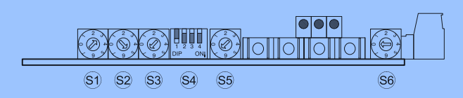
- Archetypal BC situation switches cast-off via the DCL
Proposed BC control system
The proposed control system utilizes the COA to facilitate the safe operation of a PMSWG during grid faults. In this framework, the COA is employed to optimize the performance of an industrial BC installed across the DCL. The primary objective of the COA-based controller is to maintain the DCLV within acceptable bounds by balancing the input-output power during transient grid disturbances, such as voltage dips and swells. By mimicking the strategic hunting behavior of crocodiles, the algorithm fine-tunes the controller gains to minimize oscillations in electromagnetic torque, rotor speed, and grid-side converter currents. This approach ensures the system meets GC requirements for FRTC while providing reliable grid support through reactive power injection.
COA Mathematical Model
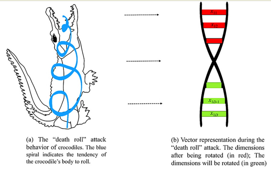
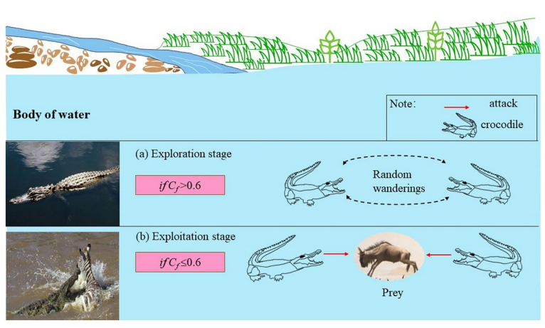
The COA is a nature-inspired metaheuristic that mimics the ambush hunting mechanisms of crocodiles, specifically focusing on infiltration (exploration) and raiding (exploitation) as seen in Figure 5. The search agents represent potential solutions, organized in a population matrix X where n is the population size and D is the dimension of each agent. Figure 6 depicts the COA flowchart.
To guide the search process, a conversion factor ( ) is utilized to balance exploration and exploitation:
| 
| (11) |
where  is set to 0.8;
  is the current generation, and
  is the maximum number of generations as in (11).
Step 1: Premeditation and Waiting Phase (Exploration)
When >0.6, the algorithm enters the exploration stage. Crocodiles swim randomly to exchange information and obtain high-quality solutions from the current best individual  ).
).
The mathematical model for this position update is:
| 
| (12) |
where  and
and  are random numbers in (0, 2) and
  is a random integer as seen in (12) and (13).
|
(a) |
|
(b) |
- (a) COA strategy: The ‘Death Roll’ hunting behavior of crocodiles; (b) COA strategy: Schematic diagram of crocodile hunting activity areas
Step 2: Attacking, Hunting, and Diet Phase (Exploitation)
When ≤0.6, the algorithm performs exploitation, mimicking a sneak attack and the signature "death roll".
- Sneak Attack: The position changes based on the proximity to the attack range, controlled by parameter C:
| 
| (13) |
where  is a random number in (0, 1) and
  is a time-varying angle.
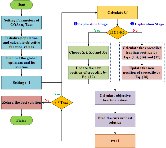
- COA flowchart
- Death Roll Attack: This simulates the crocodile's rotation to tear prey, utilizing random integers
 and
and  to influence dimension-wise updates:
| 
| (14) |
The integrated hunting model is then defined as
| 
| (15) |
- Diet Stage: After the attack, the final position is updated based on the prey's physical energy exertion (E):
| 
| (16) |
where E represents the diminishing stamina of the captured prey
Application of COA
COA is applied on the BC controller of PMSWG to fine-tune the PI controllers’ gains, as seen in Figure 7, where the configuration of the DCL in the BC-BTBC is depicted in Figure 8. This tuning is performed to improve the dynamic performance of the investigated system during normal and abnormal conditions. The optimization of the systems under study (taking control cost (CC) into account) can be formally represented in (17). The objective function for CC that is employed is written as follows:
| 
| (17) |
where  ,
,  ,
,  ,
,  , and
, and  are constants used for the estimation of the CS function, which is
  here.
here.  denotes the average time, and 100 and 6 are the number of iterations and agents, respectively.
- Control of the Crowbar system based on COA
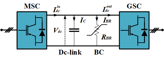
- Configuration of the DCL in the BC-BTBC
RESULTS AND DISCUSSIONS
Under unbalanced grid voltage conditions, the primary challenge encountered by the system is the excessive rise in the DCLV. Therefore, maintaining the DCLV within acceptable operating limits serves as a key indicator of the effectiveness of the proposed control strategies. To evaluate the performance of the proposed FRTC enhancement techniques, four simulation scenarios were implemented using the MATLAB/Simulink environment. Considering the short duration of the transient disturbances, the wind speed was assumed to remain constant at 12 m/s throughout the fault period. The investigated scenarios were defined according to the remaining voltage level at the PCC and were denoted as follows: S0 (100% voltage dip), S0.2 (80% voltage dip), S0.6 (40% voltage dip), and S1.2 (20% voltage swell). To demonstrate the effectiveness of the COA, the transient response of the PMSWG parameters was analyzed using a COA-PI-controller-based BC under the aforementioned operating conditions. The investigated system variables include:  ,
,  ,
,  ,
,  ,
,  ,
,  ,
,  , and
, and  . The studied PMSWG system was initially assumed to operate under steady-state (SS) conditions with a of ≈0, a system voltage Vrms = 1 pu, and a Ps = 0.96 pu. The parameters of the investigated PMSWG and BC systems (Table 2) are presented in [35].
- Simulated Parameters under the Studied Cases
Parameters | Studied cases using COA |
S0 | S0.2 | S0.6 | S1.2 |
Overvoltage at | 1.04 pu | 1.026 pu | 1.022 | 1.022 pu |
change | 0.59 pu → 0.96 pu | 0.34 pu → 0.957 pu | 0.73 pu → 0.957 pu | 0.9566 pu → 0.9583 pu |
 ripple ripple
| 0.2263 pu | 0.21 pu | 0.21 pu | - 0.1731 pu |
ripple | ± 0.03 pu | ± 0.02 pu | ± 0.015 pu | 0 pu |
| 1.09 pu | 1.091 pu | 1.091 pu | 1.091 pu |
| 0.8956 pu | 0.8955 pu | 0.895 pu | 0.8942 pu |
Three Phase Voltage Profiles (Vabc)
 : Figure 9(a) shows a 100% voltage dip (S0) lasting for 300 ms, where the voltage drops to zero and recovers at t=8.3 s.
  : Figure 9(b) illustrates an 80% voltage dip (S0.2) lasting for 600 ms, with the voltage dropping to 0.2 pu and recovering at t=8.6 s.
  : Figure 9(c) displays a 40% voltage dip (S0.6) for 1.25 s, where the voltage drops to 0.6 pu and recovers at t=9.25 s.
  : Figure 9(d) shows a 20% voltage swell (S1.2) for 1.25 s, with the voltage rising to 1.2 pu before returning to normal at t=9.25 s.
- Investigated voltage profiles
Power and Torque Response
Active Power (): Figure 10(a) displays the (pu) delivered to the grid. During VDs (S0, S0.2, S0.6), there is a significant drop in transmission at t=8 s, followed by a controlled recovery to steady state (approximately 0.96 pu) once the fault is cleared. Reactive Power (): Figure 10(b) shows the (pu). To comply with GCs and support the grid during dips, the system injects , peaking during the 100% dip (S0) and 80% dip (S0.2). Mechanical Torque (): Figure 10(c) illustrates the Electromagnetic Torque (pu). The figure highlights transient fluctuations and ripples at the beginning and end of the faults, with the COA-based controller aiming to minimize these oscillations to ensure a smoother response.
GSC Currents
Direct Current (): Figure 11(a) represents the id of the GSC. It shows the shifts in current required to manage active power and DCL stability during the fault periods. : Figure 11(b) Shows the iq of the GSC. This parameter experiences ripples and transient spikes at the fault inception (t=8 s) and clearance, particularly in the more severe 100% dip scenario.
System Stability Parameters
DCLV in Figure 12(a) displays the DCL capacitor voltage (V). This is a critical parameter for evaluating the COA-based controller. The figure shows that despite the severe faults, the controller successfully maintains the voltage near the reference value (1150 V), preventing dangerous over-voltages. Angular Speed (): Figure 12(b) Shows the angular speed (pu) of the generator. The rotor speed oscillates during the fault transients but is stabilized by the control system, returning to its steady-state value of approximately 1.09 pu.
Figure 13 displays the DCLV values for each of the scenarios that were looked at to assess the proposed method. A comparison with earlier published techniques based on FLC, MPC, SMC, or optimizers is also included in Table 3. Although the more advanced and contemporary types show respectable transient responsiveness, FCS-MPCs are vulnerable to the complexity and volatility of currents and DCLV following fault elimination due to their low switching frequency. The DCLV values did not match the required threshold (higher than 1.1 pu) in each of the VD scenarios. The recommended control methods not only enhanced the PMSWG settings' abrupt response but also preserved the DCLV value fulfilled in every situation that was examined.
- Power and Torque
- Transient SP as a result of 40% VD
- System Stability Parameters
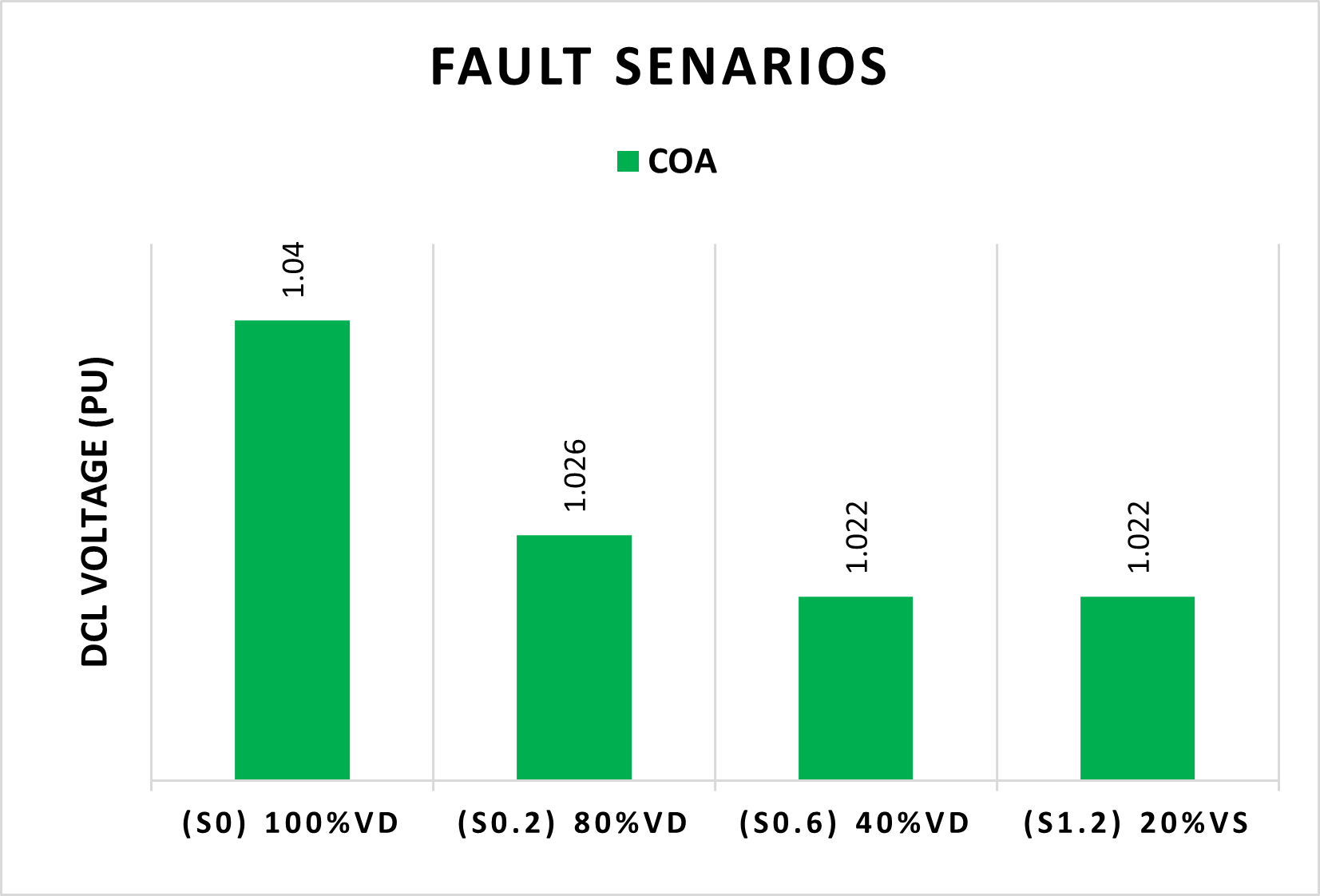
- DCLV values under the investigated scenarios
- Comparative Analysis with Previously Published Techniques
Ref | Publisher | Year | Technique | Smooth Operation | Transient response | Complexity
| DCLV during faults |
DCLV (pu) | VD (pu) | DCLV (pu) | VS (pu) |
[56] | MDPI | 2023 | NLESO and GFTSMC | √ | VH | H | 1.154 | 1 | X | X |
[35] | Taylor&Francis | 2023 | WHO-PI | √ | VH | L | 1.043 | 0.9 | X | X |
[57] | MDPI | 2022 | ESS and BC | √ | VH | VH | 1.01 | 0.4 | X | X |
[58] | MDPI | 2023 | ILP-PLL | √ | VH | VH | 1.004 | 0.35 | X | X |
[45] | SAGE | 2021 | FLC | X | H | H | 1.047 | 0.9 | X | X |
[59] | Elsevier | 2024 | Modified MSC | √ | H | L | 1.4 | asymmetrical grid faults | X | X |
COA-PI (proposed) | √ | VH | L | 1.05, 1.043, 1.035 | 1, 0.7, 0.3 | 1.022 | 0.2 |
CONCLUSIONS
The dynamic response of PMSWG under VD and VS scenarios was examined in this work employing a designed BC with COA. The system under investigation has been mathematically modeled, and COA has been applied to operate the system. Four scenarios are investigated. Table 4 summarizes all of the results that were collected. To demonstrate the efficiency and effectiveness of C, the system is run using several control schemes. The findings demonstrated that COA improves FRTC by maintaining the DC within allowable bounds, in addition to improving the dynamic response of the parameters. In comparison to A and B, the excess voltage at DCL decreased by 93.5% and 19.231%, respectively, with C in the worst case (100% VD). When it came to smoothing the power transmitted to the utility grid and reducing oscillations in the rotor's angular speed, generator electromagnetic torque, and direct and quadrature currents, C outperformed B and A. Additionally, to illustrate the contribution of the proposed strategy to sustainable development, a comparison study (Table 5) including more than a dozen published works from respectable publishers has been conducted. In conclusion, the suggested approach will contribute to the attainment of high wind energy penetration scenarios.
DECLARATION
Author Contribution
All authors contributed equally to the main contributor to this paper. All authors read and approved the final paper.
Acknowledgment
This article has been produced with the financial support of the European Union under the REFRESH—Research Excellence for REgion Sustainability and High-tech Industries project number CZ.10.03.01/00/22_003/0000048 via the Operational Programme Just Transition. Also, the authors wish to express their deep gratitude to the Ministry of Higher Education and Scientific Research of Algeria for its essential support in carrying out this study.
Conflicts of Interest
The authors declare no conflict of interest.
ABBREVIATIONS
The following abbreviations are used in this manuscript.
AFD | : | adjustable frequency drives |
BC | : | braking chopper |
BR | : | braking resistance |
BTBC | : | back-to-back converter |
PI | : | proportional-integral |
ERL | : | exponential reaching law |
ESS | : | energy storage system |
GC | : | grid-code |
GSC | : | grid-side converter |
KCL | : | Kirchhoff’s current law |
FRTC | : | Fault ride-through capability |
MPPT | : | maximum power point tracking |
FACTS | : | Flexible AC Transmission Systems |
SDGs | : | Sustainable Development Goals |
SS | : | Sustainable sources |
WF | : | Wind farm |
PMSWG | : | permanent magnet synchronous wind generator |
SMC | : | sliding mode control |
SPWM | : | sinusoidal pulse width modulation |
SRF | : | Synchronous reference frame |
PLL | : | Phase-locked loop |
VD | : | Voltage dip |
MSC | : | machine-side converter |
OTC | : | optimal torque control |
PCC | : | point of common coupling |
DCL | : | DC link |
REFERENCES
- N. Musa Tahir, A. Yawale Babawuro, F. M. Alelaj, B. Bala Muhammad, S. Sadi Shitu, and I. Abubakar Umar, "Control of a Single-Link Flexible Manipulator: Integration of Output-Based Filter With Model Predictive Constraint," Journal of Physics: Conference Series, vol. 3191, no. 1, p. 012043, 2026, https://doi.org/10.1088/1742-6596/3191/1/012043.
- F. Alelaj and A. Alqallaf, "Optimization of the Tilt Angle of the Photo-Voltaic Module in Kuwait," in 2019 IEEE 10th GCC Conference & Exhibition (GCC), pp. 1–6, 2019, https://doi.org/10.1109/GCC45510.2019.1570525127.
- F. Alelaj and A. Alqallaf, "Impact of Solar Irradiation on the Performance Ratio of the Photovoltaic Module," in 2019 IEEE 10th GCC Conference & Exhibition (GCC), pp. 1–4, 2019, https://doi.org/10.1109/GCC45510.2019.9087579.
- M. A. Bou-Rabee, F. M. Alelaj, and H. Al-Sairfi, "Quantifying the Economic Loss and Operational Implications of Air Pollution on Grid-Connected PV Systems in the Arabian Peninsula: A Machine Learning-Based Analysis," IEEE Access, vol. 14, pp. 4180–4188, 2026, https://doi.org/10.1109/ACCESS.2025.3649764.
- M. Fadel, F. M. Alelaj, H. Al-Sairfi, and M. Ahmed, "Adaptive Fuzzy Energy Management of Wind-Battery Systems With Flexible Desalination Load," Energy Science & Engineering, 2026, https://doi.org/10.1002/ese3.70570.
- A. Raj, A. Nandi, S. K. Sawant, A. K. Swain, A. P. Yadav, A. K. Parida, M. M. Mahmoud, V. Blazek, D. E. M. Wapet, and S. N. Fahmy, "Adaptive Q-Wavelet Transform and Kalman Filtering for Power Quality Disturbance Prediction and Carbon Emission Impact Analysis in Smart Grids," Engineering Reports, vol. 8, no. 5, p. e70825, 2026, https://doi.org/10.1002/eng2.70825.
- W. F. Mbasso, A. Harrison, I. Dagal, M. M. Mahmoud, M. K. Singla, P. Jangir, and M. S. Shaikh, "MAAPO-E: An Entropy-Guided, Constraint-Aware Membrane Protozoa Optimizer for High-Dimensional Numerical and Engineering Optimization," Journal of Membrane Computing, vol. 8, no. 2, pp. 264–283, 2026, https://doi.org/10.1007/s41965-025-00208-w.
- A. Assas, H. Guentri, T. Alaoui, V. Blazek, A. Dahbi, A. Ma'arif, E. Touti, and M. M. Mahmoud, "Robust LQR Control Design for High Efficiency Battery Supercapacitor Hybrid Storage Systems," International Journal of Robotics and Control Systems, vol. 6, no. 2, pp. 1405–1425, 2026, https://pubs2.ascee.org/index.php/IJRCS/article/view/1933.
- A. T. Hassan, I. M. Elzein, M. M. Mahmoud, V. Blazek, A. Ma'arif, E. Touti, and A.-M. M. Ali, "Intelligent Chopper and RSC Control Using Crayfish Optimization for Dynamic Stability and Fault Ride-Through of DFIG Wind Turbines," International Journal of Robotics and Control Systems, vol. 6, no. 1, pp. 693–717, 2026, https://doi.org/10.31763/ijrcs.v6i1.2002.
- S. Heroual, B. Belabbas, K. Ayati, R. Haloui, A. T. Hassan, A. Ma'arif, M. M. Mahmoud, and V. Blazek, "Genetic Algorithm Tuned Controllers for High-Performance Indirect Field-Oriented Control in DFIG-Based WECS," Buletin Ilmiah Sarjana Teknik Elektro, vol. 8, no. 1, pp. 294–310, 2026, https://journal2.uad.ac.id/index.php/biste/article/view/15529.
- M. Tarek, I. M. Elzein, M. M. Mahmoud, A. M. El-Rifaie, H. S. Hussein, W. F. Mbasso, and A. M. Ewais, "Intelligent Frequency Regulation in Islanded Microgrids Using a Crayfish-Tuned FO–(PD–PI) Controller With Energy Storage Coordination," Journal of Low Frequency Noise, Vibration and Active Control, 2026, https://doi.org/10.1177/14613484261429576.
- A. G. Olabi, K. Obaideen, M. A. Abdelkareem, M. N. AlMallahi, N. Shehata, A. H. Alami, A. Mdallal, A. A. M. Hassan, and E. T. Sayed, "Wind Energy Contribution to the Sustainable Development Goals: Case Study on London Array," Sustainability, vol. 15, no. 5, p. 4641, 2023, https://doi.org/10.3390/su15054641.
- S. Kumar, N. Kumar, and S. Vivekadhish, "Millennium Development Goals (MDGs) to Sustainable Development Goals (SDGs): Addressing Unfinished Agenda and Strengthening Sustainable Development and Partnership," Indian Journal of Community Medicine, vol. 41, no. 1, pp. 1–4, 2016, https://doi.org/10.4103/0970-0218.170955.
- P. P. Walsh, E. Murphy, and D. Horan, "The Role of Science, Technology and Innovation in the UN 2030 Agenda," Technological Forecasting and Social Change, vol. 154, p. 119957, 2020, https://doi.org/10.1016/j.techfore.2020.119957.
- W. Fei, A. Opoku, K. Agyekum, J. A. Oppon, V. Ahmed, C. Chen, and K. L. Lok, "The Critical Role of the Construction Industry in Achieving the Sustainable Development Goals (SDGs): Delivering Projects for the Common Good," Sustainability, vol. 13, no. 16, p. 9112, 2021, https://doi.org/10.3390/su13169112.
- V. J. Subiela-Ortín, B. Peñate-Suárez, and J. A. de la Fuente-Bencomo, "Main Technical and Economic Guidelines to Implement Wind/Solar-Powered Reverse-Osmosis Desalination Systems," Processes, vol. 10, no. 4, p. 653, 2022, https://doi.org/10.3390/pr10040653.
- M. Miloudi, H. Miloudi, S. A. E. M. Ardjoun, I. M. Elzein, M. M. Mahmoud, W. F. Mbasso, H. S. Hussein, and A. M. Ewais, "Comprehensive Experimental Performance Investigation of Conducted Electromagnetic Interference in Split-Phase Induction Motors: Common-Mode," Journal of Low Frequency Noise, Vibration and Active Control, vol. 45, no. 2, pp. 861–880, 2026, https://doi.org/10.1177/14613484251411703.
- M. T. Mohamed, I. M. Elzein, A. M. El-Rifaie, M. M. Mahmoud, A. Ma'arif, D. E. M. Wapet, T. H. Mohamed, V. Blazek, and S. N. Fahmy, "Sustainable Energy Management in Islanded Microgrids via HHO–BE Tuned Adaptive Controllers and Demand-Side Flexibility," Engineering Reports, vol. 8, no. 1, p. e70561, 2026, https://doi.org/10.1002/eng2.70561.
- S. Nadweh, I. M. Elzein, D. E. M. Wapet, and M. M. Mahmoud, "Optimizing Control of Single-Ended Primary Inductor Converter Integrated With Microinverter for PV Systems: Imperialist Competitive Algorithm," Energy Exploration & Exploitation, vol. 44, no. 1, pp. 554–577, 2026, https://doi.org/10.1177/01445987251382002.
- N. V. A. Ravikumar, R. Sasidhar, V. Manoj, C. Mutta, M. C. S. Reddy, K. J. Narayana, D. E. M. Wapet, and M. M. Mahmoud, "Design and Real-Time Simulations of Robust Controllers for Uncertain Multi-Input Wind Turbine," Energy Exploration & Exploitation, vol. 44, no. 1, pp. 276–292, 2026, https://doi.org/10.1177/01445987251373101.
- M. Mohseni and S. M. Islam, "Review of International Grid Codes for Wind Power Integration: Diversity, Technology and a Case for Global Standard," Renewable and Sustainable Energy Reviews, vol. 16, no. 6, pp. 3876–3890, 2012, https://doi.org/10.1016/j.rser.2012.03.039.
- S. A. E. M. Ardjoun, M. Denai, and M. Abid, "A Robust Power Control Strategy to Enhance LVRT Capability of Grid-Connected DFIG-Based Wind Energy Systems," Wind Energy, vol. 22, no. 6, pp. 834–847, 2019, https://doi.org/10.1002/we.2325.
- M. M. Mahmoud, M. M. Aly, H. S. Salama, and A. M. M. Abdel-Rahim, "Dynamic Evaluation of Optimization Techniques-Based Proportional-Integral Controller for Wind-Driven Permanent Magnet Synchronous Generator," Wind Engineering, vol. 45, no. 3, pp. 696–709, 2021, https://doi.org/10.1177/0309524X20930421.
- S. Saeed, R. Asghar, F. Mehmood, H. Saleem, B. Azeem, and Z. Ullah, “Evaluating a hybrid circuit topology for fault-ride through in DFIG-based wind turbines,” Sensors, vol. 22, no. 23, p. 9314, 2022, https://doi.org/10.3390/s22239314.
- M. Tsili and S. Papathanassiou, "A Review of Grid Code Technical Requirements for Wind Farms," IET Renewable Power Generation, vol. 3, no. 3, pp. 308–332, 2009, https://doi.org/10.1049/iet-rpg.2008.0070.
- M. M. Mahmoud, M. K. Ratib, M. M. Aly, and A. M. M. Abdel-Rahim, "Wind-Driven Permanent Magnet Synchronous Generators Connected to a Power Grid: Existing Perspective and Future Aspects," Wind Engineering, vol. 46, no. 1, pp. 189–199, 2022, https://doi.org/10.1177/0309524X211022728.
- M. Nasiri and R. Mohammadi, "Peak Current Limitation for Grid Side Inverter by Limited Active Power in PMSG-Based Wind Turbines During Different Grid Faults," IEEE Transactions on Sustainable Energy, vol. 8, no. 1, pp. 3–12, 2017, https://doi.org/10.1109/TSTE.2016.2578042.
- M. Nasiri, A. Arzani, and M. Savaghebi, "Current Limitation for the Machine Side Converter of Permanent Magnet Synchronous Generator Wind Turbines During Grid Faults," IET Renewable Power Generation, vol. 14, no. 17, pp. 3448–3456, 2020, https://doi.org/10.1049/iet-rpg.2019.1246.
- M. M. Mahmoud, B. S. Atia, Y. M. Esmail, M. Bajaj, D. E. M. Wapet, M. K. Ratib, M. B. Hossain, K. M. AboRas, and A.-M. M. Abdel-Rahim, "Evaluation and Comparison of Different Methods for Improving Fault Ride-Through Capability in Grid-Tied Permanent Magnet Synchronous Wind Generators," International Transactions on Electrical Energy Systems, vol. 2023, no. 1, p. 7717070, 2023, https://doi.org/10.1155/2023/7717070.
- M. Nasiri, S. Mobayen, B. Faridpak, A. Fekih, and A. Chang, "Small-Signal Modeling of PMSG-Based Wind Turbine for Low Voltage Ride-Through and Artificial Intelligent Studies," Energies, vol. 13, no. 24, p. 6685, 2020, https://doi.org/10.3390/en13246685.
- M. A. Mostafa, E. A. El-Hay, and M. M. ELkholy, "Recent Trends in Wind Energy Conversion System With Grid Integration Based on Soft Computing Methods: Comprehensive Review, Comparisons and Insights," Archives of Computational Methods in Engineering, vol. 30, no. 3, pp. 1439–1478, 2023, https://doi.org/10.1007/s11831-022-09842-4.
- S. Heroual, B. Belabbas, Y. Diab, M. M. Mahmoud, T. Allaoui, and N. Benabdallah, "Optimizing Power Flow in Photovoltaic-Hybrid Energy Storage Systems: A PSO and DPSO Approach for PI Controller Tuning," International Transactions on Electrical Energy Systems, vol. 2025, no. 1, p. 9958218, 2025, https://doi.org/10.1155/etep/9958218.
- F. Menzri, T. Boutabba, I. Benlaloui, L. Chrifi-Alaoui, A. Alkuhayli, U. Khaled, and M. M. Mahmoud, "Applications of Novel Combined Controllers for Optimizing Grid-Connected Hybrid Renewable Energy Systems," Sustainability, vol. 16, no. 16, p. 6825, 2024, https://doi.org/10.3390/su16166825.
- J. X. Jin, R. H. Yang, R. T. Zhang, Y. J. Fan, Q. Xie, and X. Y. Chen, "Combined Low Voltage Ride Through and Power Smoothing Control for DFIG/PMSG Hybrid Wind Energy Conversion System Employing a SMES-Based AC-DC Unified Power Quality Conditioner," International Journal of Electrical Power & Energy Systems, vol. 128, p. 106733, 2021, https://doi.org/10.1016/j.ijepes.2020.106733.
- M. M. Mahmoud, "Improved Current Control Loops in Wind Side Converter With the Support of Wild Horse Optimizer for Enhancing the Dynamic Performance of PMSG-Based Wind Generation System," International Journal of Modelling and Simulation, vol. 43, no. 6, pp. 952–966, 2023, https://doi.org/10.1080/02286203.2022.2139128.
- F. Menzri, T. Boutabba, I. Benlaloui, H. Bawayan, M. I. Mosaad, and M. M. Mahmoud, "Applications of Hybrid SMC and FLC for Augmentation of MPPT Method in a Wind-PV-Battery Configuration," Wind Engineering, vol. 48, no. 6, pp. 1186–1202, 2024, https://doi.org/10.1177/0309524X241254364.
- O. M. Lamine, N. Bessous, B. Abdelhalim, F. A. Banakhr, M. I. Mosaad, O. Mammeri, and M. M. Mahmoud, "A Combination of INC and Fuzzy Logic-Based Variable Step Size for Enhancing MPPT of PV Systems," International Journal of Robotics and Control Systems, vol. 4, no. 2, pp. 877–892, 2024, https://doi.org/10.31763/ijrcs.v4i2.1428.
- B. S. Atia, M. M. Mahmoud, I. M. Elzein, A.-M. M. Abdel-Rahim, A. Alkuhayli, U. Khaled, A. Beroual, and S. A. Shaaban, "Applications of Kepler Algorithm-Based Controller for DC Chopper: Towards Stabilizing Wind Driven PMSGs Under Nonstandard Voltages," Sustainability, vol. 16, no. 7, p. 2952, 2024, https://doi.org/10.3390/su16072952.
- M. Nasiri and A. Arzani, "Robust Control Scheme for the Braking Chopper of PMSG-Based Wind Turbines—A Comparative Assessment," International Journal of Electrical Power & Energy Systems, vol. 134, p. 107322, 2022, https://doi.org/10.1016/j.ijepes.2021.107322.
- B. Babaghorbani, M. T. Beheshti, and H. A. Talebi, "A Lyapunov-Based Model Predictive Control Strategy in a Permanent Magnet Synchronous Generator Wind Turbine," International Journal of Electrical Power & Energy Systems, vol. 130, p. 106972, 2021, https://doi.org/10.1016/j.ijepes.2021.106972.
- K. Tahir, C. Belfedal, T. Allaoui, and G. Champenois, "A New Control Strategy of WFSG-Based Wind Turbine to Enhance the LVRT Capability," International Journal of Electrical Power & Energy Systems, vol. 79, pp. 172–187, 2016, https://doi.org/10.1016/j.ijepes.2016.01.008.
- E. H. Dursun and A. A. Kulaksiz, "Second-Order Sliding Mode Voltage-Regulator for Improving MPPT Efficiency of PMSG-Based WECS," International Journal of Electrical Power & Energy Systems, vol. 121, p. 106149, 2020, https://doi.org/10.1016/j.ijepes.2020.106149.
- Y. Errami, M. Ouassaid, and M. Maaroufi, "A Performance Comparison of a Nonlinear and a Linear Control for Grid Connected PMSG Wind Energy Conversion System," International Journal of Electrical Power & Energy Systems, vol. 68, pp. 180–194, 2015, https://doi.org/10.1016/j.ijepes.2014.12.027.
- M. Nasiri, S. Mobayen, and Q. M. Zhu, "Super-Twisting Sliding Mode Control for Gearless PMSG-Based Wind Turbine," Complexity, vol. 2019, p. 6141607, 2019, https://doi.org/10.1155/2019/6141607.
- M. M. Mahmoud, H. S. Salama, M. M. Aly, and A. M. M. Abdel-Rahim, "Design and Implementation of FLC System for Fault Ride-Through Capability Enhancement in PMSG-Wind Systems," Wind Engineering, vol. 45, no. 5, pp. 1361–1373, 2021, https://doi.org/10.1177/0309524X20981773.
- M. M. Mahmoud, M. K. Ratib, M. M. Aly, and A. M. M. Abdel-Rahim, "Application of Whale Optimization Technique for Evaluating the Performance of Wind-Driven PMSG Under Harsh Operating Events," Process Integration and Optimization for Sustainability, vol. 6, no. 2, pp. 447–470, 2022, https://doi.org/10.1007/s41660-022-00224-8.
- K. H. Kim, Y. C. Jeung, D. C. Lee, and H. G. Kim, "LVRT Scheme of PMSG Wind Power Systems Based on Feedback Linearization," IEEE Transactions on Power Electronics, vol. 27, no. 5, pp. 2376–2384, 2012, https://doi.org/10.1109/TPEL.2011.2171999.
- M. Nasiri, J. Milimonfared, and S. H. Fathi, "A Review of Low-Voltage Ride-Through Enhancement Methods for Permanent Magnet Synchronous Generator Based Wind Turbines," Renewable and Sustainable Energy Reviews, vol. 47, pp. 399–415, 2015, https://doi.org/10.1016/j.rser.2015.03.079.
- P. Xing, L. Fu, G. Wang, Y. Wang, and Y. Zhang, "A Compositive Control Method of Low-Voltage Ride Through for PMSG-Based Wind Turbine Generator System," IET Generation, Transmission & Distribution, vol. 12, no. 1, pp. 117–125, 2018, https://doi.org/10.1049/IET-GTD.2017.0270.
- L. S. Barros and C. M. V. Barros, "An Internal Model Control for Enhanced Grid-Connection of Direct-Driven PMSG-Based Wind Generators," Electric Power Systems Research, vol. 151, pp. 440–450, 2017, https://doi.org/10.1016/j.epsr.2017.06.014.
- V. F. Mendes, F. F. Matos, S. Y. Liu, A. F. Cupertino, H. A. Pereira, and C. V. de Sousa, "Low Voltage Ride-Through Capability Solutions for Permanent Magnet Synchronous Wind Generators," Energies, vol. 9, no. 1, p. 59, 2016, https://doi.org/10.3390/en9010059.
- M. Wang, Y. Tian, X. Feng, and G. Chen, "A Hybrid LVRT Control Scheme for PMSG Wind Power System," in 2012 IEEE 7th International Power Electronics and Motion Control Conference (IPEMC-ECCE Asia), pp. 1173–1177, 2012, https://doi.org/10.1109/IPEMC.2012.6258996.
- S. Marmouh, M. Boutoubat, L. Mokrani, and M. Machmoum, "A Coordinated Control and Management Strategy of a Wind Energy Conversion System for a Universal Low-Voltage Ride-Through Capability," International Transactions on Electrical Energy Systems, vol. 29, no. 8, p. e12035, 2019, https://doi.org/10.1002/2050-7038.12035.
- M. K. K. Prince, M. T. Arif, A. Gargoom, M. W. Altaf, K. M. Muttaqi, and M. E. Haque, "Coordinated Control of Grid-Connected PMSG Based Wind Energy System With STATCOM and Supercapacitor Energy Storage," IEEE Transactions on Industry Applications, vol. 58, no. 6, pp. 7254–7268, 2022, https://doi.org/10.1109/TIA.2022.3191066.
- M. H. Qais, H. M. Hasanien, and S. Alghuwainem, "Low Voltage Ride-Through Capability Enhancement of Grid-Connected Permanent Magnet Synchronous Generator Driven Directly by Variable Speed Wind Turbine: A Review," The Journal of Engineering, vol. 2017, no. 13, pp. 1750–1754, 2017, https://doi.org/10.1049/joe.2017.0632.
- Z. Kang and J. Li, "Zero-Voltage Ride-Through Scheme of PMSG Wind Power System Based on NLESO and GFTSMC," Electronics, vol. 12, no. 20, p. 4348, 2023, https://doi.org/10.3390/electronics12204348.
- T. H. Nguyen, A. Nawaz, P. Sreekumar, A. Natsheh, V. Akre, and T. L. Van, "Implementation and Validation for Multitasks of a Cost-Effective Scheme Based on ESS and Braking Resistors in PMSG Wind Turbine Systems," Energies, vol. 15, no. 21, p. 8282, 2022, https://doi.org/10.3390/en15218282.
- S. W. Ali, C.-L. Su, A. K. Verma, C. B. Mellado, and C. Gonzalez-Castano, "Enhancing Single-Phase Grid Integration Capability of PMSG-Based Wind Turbines to Support Grid Operation Under Adverse Conditions," Sustainability, vol. 15, no. 13, p. 10662, 2023, https://doi.org/10.3390/su151310662.
- Z. Wang, X. Gao, L. Liu, Z. Ren, D. Zhang, G. Zhu, C. Jia, V. Terzija, and L. Ding, "Enhanced DC-Link Voltage Control of PMSG-Based Wind Turbine Generators by Machine-Side Converter During Asymmetrical Grid Faults," International Journal of Electrical Power & Energy Systems, vol. 155, p. 109638, 2024, https://doi.org/10.1016/j.ijepes.2023.109638.
Basiony Shehata Atia (Crocodile Optimizer-Based DC Chopper Control for Voltage Dip and Swell Mitigation in PMSG-Based WT)