ISSN: 2685-9572 Buletin Ilmiah Sarjana Teknik Elektro
Vol. 8, No. 1, February 2026, pp. 311-330
Design of MMC-STATCOM Controller Using an Adaptive PID Controller Supported by a Grey Model
Mohammed Moanes Ezzaldean Ali 1, Qusay S. Kadhim 2
1 College of Electrical Engineering, University of Technology-Iraq, Iraq
2 Al-Mussaib Technical College, Al-Furat Al-Awsat Technical University, Najaf 54001, Iraq
ARTICLE INFORMATION |
| ABSTRACT |
Article History: Received 22 November 2025 Revised 07 February 2026 Accepted 10 March 2026 |
| 
The Static Synchronous Compensator (STATCOM) is recognized as one of the most advanced and effective technologies within the Flexible AC Transmission Systems (FACTS) family, due to its rapid dynamic response and high efficiency in regulating reactive power flow. However, conventional two- and three-level STATCOM topologies suffer from limited scalability and high harmonic distortion. This paper addresses these challenges by employing a STATCOM based on Modular Multilevel Converter (MMC). The significant contribution of this work is the introduction of a novel control strategy for MMC-STATCOM systems which is an adaptive PID controller integrated with a Grey Prediction Model. In the proposed scheme, the PID gains are continuously adapted based on predicted future error values obtained from the GM(1,1) grey model, rather than instantaneous measured errors, enabling proactive compensation under dynamic operating conditions. The performance of the proposed controller is evaluated in MATLAB/Simulink environment and by using a 12 MVA, 34.5 kV MMC-STATCOM system with a full-bridge topology consisting of 22 submodules per phase. Under balanced load condition, the results demonstrated that the adaptive grey-PID controller significantly reduced the total harmonic distortion (THD) of the grid current by 43.75% as compared to conventional PI controller. Under a severe unbalanced load condition, the total harmonic distortion of the grid current is reduced by 33.42%. Furthermore, the proposed controller successfully restored balance to the grid voltage and current and maintained a stable DC-link voltage under unbalanced load conditions. Additionally, the suggested controller achieved a fast-settling time of 0.04 s during transient conditions, this conclusively demonstrates its superior robustness and rapid dynamic response. Despite the additional computational effort introduced by the grey predictor model, it remains suitable for real time implementation due to its low order structure and limited data window. |
Keywords: Multilevel Converter; MATLAB; Simulink; Grey Predictor; THD; Adaptive PID Control |
Corresponding Author: Mohammed Moanes Ezzaldean Ali, College of Electrical Engineering, University of Technology-Iraq, Iraq. Email: mohammedmoanes.e.ali@uotechnology.edu.iq |
This work is open access under a Creative Commons Attribution-Share Alike 4.0 
|
Document Citation: M. M. E. Ali and Q. S. Kadhim, “Design of MMC-STATCOM Controller Using an Adaptive PID Controller Supported by a Grey Model,” Buletin Ilmiah Sarjana Teknik Elektro, vol. 8, no. 1, pp. 311-330, 2026, DOI: 10.12928/biste.v8i1.15426. |
- INTRODUCTION
Modern power systems are increasingly challenged by the ongoing growth in demand and the large-scale integration of renewable energy sources with inherently variable characteristics [1]-[3]. Ensuring high power quality, maintaining voltage stability, and mitigating transient disturbances have therefore become essential requirements for reliable and efficient power networks [4]-[6]. Within this context, the STATCOM has emerged as one of the most advanced and effective technologies in the FACTS family. Owing to its fast dynamic response and high efficiency in regulating reactive power flow [7]-[10]. Although two-level and three-level STATCOM topologies are widely used, they still suffer from drawbacks such as bulky line-frequency transformers, limited scalability, and high harmonic distortion in their output voltage waveforms [11][12]. To address these issues, multilevel converter topologies particularly the Modular Multilevel Converter (MMC) have been introduced [13]-[15]. MMC-based STATCOM provides reduced harmonic content, and the capability to exchange the reactive power through a common DC bus [16]. Additionally, they facilitate advanced roles, such as negative-sequence compensation under unbalanced grid conditions without operational interruptions [17]-[19].
Several recent studies have highlighted the importance of advanced control strategies for MMC-STATCOM systems. For example, Diab et al. (2020) formulated a joint optimization strategy for PI controller tuning using Harris Hawks Optimization and Atom Search Optimization, achieving reduced THD, voltage ripple, and circulating current in a 12 MVA, 34.5 kV [20]. Stepanov et al. (2023) proposed an MMC-Delta-STATCOM model with integrated energy storage, allowing flexible interfacing of converter and storage models using super-capacitors and batteries [21]. Eroğlu et al. (2023) developed a multi-objective control strategy for cascaded H-bridge multilevel converter (CHB-MLC) based battery D-STATCOM systems, incorporating bidirectional power flow, fault-tolerant SOC balancing, and harmonic reduction schemes, which significantly reduced THD under normal and fault conditions [22]. Liu et al. (2025) introduced a DBS-less MMC-MTDC system for large-scale offshore wind integration. Their proposed architecture combines hybrid MMCs with enhanced DC choppers and high-speed optical-fiber communication to achieve robust AC/DC fault ride-through and improved economic efficiency [23].
Although various optimization-based, Model predictive and multi-objective control strategies have been proposed for STATCOM systems, most existing approaches rely on offline tuning procedures or control actions based on instantaneous error signals. Such methods may exhibit degraded performance under transients and rapidly changing grid conditions. Therefore, there remains a need for control strategies that can inherently adapt to system variations in real time without complex tuning procedures, particularly under severe unbalanced operating conditions [24][25].
The primary contribution of this work is the design of an adaptive Grey-PID controller for MMC-STATCOM systems, where the PID gains ( ,
,  , and
, and  ) are online-updated based on the predicted future error obtained from the GM (1,1) model instead of present measured error. This predictive technique enables anticipatory compensation, resulting in faster dynamic response and improved harmonic performance compared to conventional PI controller. This paper evaluates the performance of the proposed controller in 12 MVA MMC-STATCOM system, focusing on internal energy balance and THD reduction. PI approach is selected as the benchmark due to its widespread industrial adoption and well-established performance characteristics, allowing a clear and fair evaluation of the proposed technique.
The remainder sections of this paper are organized as follows: Section 2 reviews MMC topologies and modeling; Section 3 presents the proposed MMC-STATCOM controller; Section 4 details the simulation of the controller; Section 5 outlines the results and discussions and Section 6 provides the final conclusions.
- MMC TOPOLOGIES AND MODELING
The MMC operates as an efficient STATCOM, serving as an interface between power sources and the power grid [26]-[28]. The MMC significantly enhances overall grid performance by providing the reactive power requirements of the load [29]. The topology of MMC-STATCOM employed, in this work, is a full bridge modular multilevel converter formed of 22 modules per phase power converter [20],[30]. This topology is flexible, because it is capable of controlling the negative-sequence reactive power and consequently enables circulating current control among the three legs of the Double Star connection. This paper focuses on minimizing the total harmonic distortion, maintaining capacitor voltage ripple within permissible limits and minimizing circulating currents. The equivalent circuit of one phase of the MMC is illustrated in Figure 1, where the currents of the upper and the lower arm ( and
and  ) consist of the following components:
  ,
,  and
and  which represent DC current, circulating current, and output current, respectively [31][32]. The upper and lower currents are given by:
|  and and 
| (1) |
The output current is obtained by [33]:
| 
| (2) |
Based on the  -frame, the output currents are controlled,
  to transformation is given by:
| 
| (3) |
Where  ,
, are components of the voltages or currents, respectively.
  ,
,  ,
,  are the three-phase components of the voltages or currents in -frame and
  is the phase angle. Differences between references and actual current components are considered as current errors (
 and
and  ). According to the two current error signals, two adaptive PID current controllers used to generate reference
  - and
- and  -axis voltage commands (
 and
and  ). The reference -voltage commands are transformed into the -voltage using the following matrix [34]:
| 
| (4) |
-frame reference voltages are superimposed onto the signals of the arm modulation to control the operation of the modular multilevel converter. The common-mode current ( ), which passes through each leg of an MMC-STATCOM, is calculated as:
| 
| (5) |
From the circuit of Figure 1, the upper and lower arm voltages are given by [35]:
|  and and 
| (6) |
Where  is the output voltage,
  and
and  represent the arm inductance and resistance, respectively. From (5) and (6), the voltage drops of the arm inductor due to is found in [26]:
| 
| (7) |
The voltage drops of the arm inductor due to is found in [26]:
| 
| (8) |
Where ( ) the voltage drops due to . The DC current component is controlled via leg voltage control to reach balance between the input power and output power of the modular multilevel converter. To simplify the analysis, is ignored as their magnitude is negligible, then the simplified circulating current model is expressed as [28]:
| 
| (9) |
The circulating current in the -frame appears in the following equation as:
| 
| (10) |
In the synchronous -frame which rotates at angular frequency of  , where
  is the fundamental grid frequency. The equation will be [29]:
| 
| (11) |
The measured arm currents are processed within the control loop to estimate the actual circulating currents. These actual currents are converted into -frame yielding  and
and  currents. The -axis and -axis reference currents are set to zero. Comparing the actual circulating current with its reference produces the current error and . Here, a controller is employed to generate reference and that minimize the current errors. Using the transformation in (4), the reference voltages are transformed from -frame into -frame. The three reference voltage signals (
 ,
,  ,
,  )
) are employed to generate the arm modulation signals for MMC operation. The controller of the STATCOM is responsible to regulate reactive power. To achieve this objective, the controller generates gating signals for the MOSFETs. Adjusting the switching pattern determines whether the STATCOM operates in capacitive mode or inductive mode. The closed-loop control ensures fast and accurate operation. The following section details the proposed adaptive grey-PID control strategy that controls the system derived in this section.
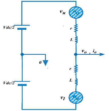
Figure 1. Equivalent circuit of one phase of MMC-STATCOM [26]
- THE PROPOSED MMC-STATCOM CONTROLLER
Although PI or PID controllers are widely used in MMC-STATCOM systems, the adaptive controller offers faster response, especially under transient operating conditions. Typically, tuning of adaptive PID controller relies on the instantaneous measured values [36]. In the suggested technique, the predicted variable is implemented instead of the measured value. The predictor employed, in this study, is the Grey Model GM(1,1) which updates the PID gains using only a limited set of previous data. Owing to the simple mathematical structure of GM(1,1) model, the prediction process can be executed with minimal computational effort to provide accurate predictions [37]. Despite the additional prediction algorithm, the overall computational burden remains low, making the proposed method appropriate for real-time MMC-STATCOM control [37][38]. The concept behind this predictor is based on an operation named the accumulated generating operation (AGO) on data series to create a sequence. The sequence is then utilized to develop a difference equation. Least-squares algorithm is used to obtain the coefficients of the difference equation; The difference equation can then be solved. Based on this solution, one step ahead data is predicted using the Inverse accumulating generation operation (IAGO). Grey theory presents a family of grey models denoted as GM(m,N), where  represents the order of the difference equation and
  denotes the number of inputs. GM(1,1) is a 1st order model with one input variable and is the most widely used for prediction issues. This study employs three GM(1,1) predictors to predict the variations in
  ,
,  , and
, and  . Each predictor is used directly to modify its associated adaptive PID parameters. This strategy is useful when each variable is controlled by a separate PID-controller and when precise control of each channel is desired [37]-[39]. Procedure of developing GM(1,1) model and obtaining its predicted values is outlined below, the symbol
  refers to the or currents. In the case of voltage , the symbol can be replaced by
  :
:
- The sequence of initial information (current values) is established as [40]:
| 
| (12) |
The parameter  denotes the size of the data sequence used by the grey prediction model. To sufficiently capture the system variation, a minimum of 4-points is required. In this study, is set to 5 as a compromise between prediction accuracy and computational simplicity. A sliding window strategy is employed to update the sequence; the most recent one is appended and the oldest data point is eliminated, maintaining a constant vector dimension. In subsequent sampling time, the sequence
  is updated as follows:
  and so on [38].
- The AGO of the information sequence is formulated as [37][40]:
| 
| (13) |
where
| 
| (14) |
The average of two consecutive data is:
| 
| (15) |
- The difference equation of grey model is given as follows:
| 
| (16) |
The equivalent first order differential equation has the follow form:
| 
| (17) |
- The coefficients of (17) are obtained using the least-square technique as follows [39]:
| 
| (18) |
where the data matrix  and the data vector
Solution of (18) at the time ( ) will be [39],[41]:
| 
| (19) |
- Predicted current at the time () is calculated by applying the inverse AGO as expressed in (20) [42]:
| 
| (20) |
GM(1,1) predicts the next state based on the last 5 values; this approach requires minimal information and calculation resulting in an estimation with acceptable accuracy. The structure of the controller is comprised of the steps below:
- Evaluation of the estimated current error:
| 
| (21) |
where  is the reference (required) current. The adaptive mechanism is based on the predicted error rather than the instantaneous error.
- Determination of the incremental gain updates (
 ,
,  and
and  ). The following performance function is considered [41]:
| 
| (22) |
The control function of the PID controller can be expressed as [37]:
| 
| (23) |
Discretization of (23) results in the following equation [37]:
| 
| (24) |
 ,
,  and
and  functions are determined as [38]:
The adaptation law is developed by applying gradient descent algorithm combined with chain rule to minimize the performance function  . The corresponding update expressions are given as [40]:
Where  is the learning coefficient (
 ; larger accelerates the adaptation process but may induce oscillations, whereas a smaller μ results in a smoother but slower convergence. In this study, μ is selected empirically to achieve a compromise between adaptation speed and closed-loop stability, and its value is kept constant throughout the simulations.
  represents the Jacobian describing the sensitivity of the predicted plant output (
 ) with respect to the output of the controller (
 ). By substituting (21), (22), and (24) into (28) to (30), the following equations are obtained [37]:
- Tuning of the adaptive PID parameters by updating , and :
| 
|
|
The Initial values of proportional, integral and derivative coefficients used, in this work, are listed in Table 1. The proposed algorithm employed for the online adaptation process is presented in Figure 2. This algorithm is executed in parallel to independently tune the three PID control loops addressed in this study: , and the DC-link voltage . The adaptation process is contingent on the accurate prediction of future values rather than on the actual, measured values. Consequently, the adaptation mechanism undergoes continuous adjustment to address gradual or sudden, minor or substantial variations in current or voltage. A conventional PID controller utilizes the derivative term to anticipate error tendencies; however, derivative term is highly sensitive to high-frequency noise and might cause control instability. Conversely, the Grey Predictor GM(1,1) employs the AGO technique, which inherently functions as a low-pass filter by smoothing the data sequence. Consequently, the adaptive PID updates its gains based on a denoised predicted state, providing a more robust and proactive response compared to traditional control.
Table 1. Initial values of , and
The controller |
|
|
|
DC voltage controller | 10 | 80 | 0 |
and controller | 0.8 | 8 | 0 |
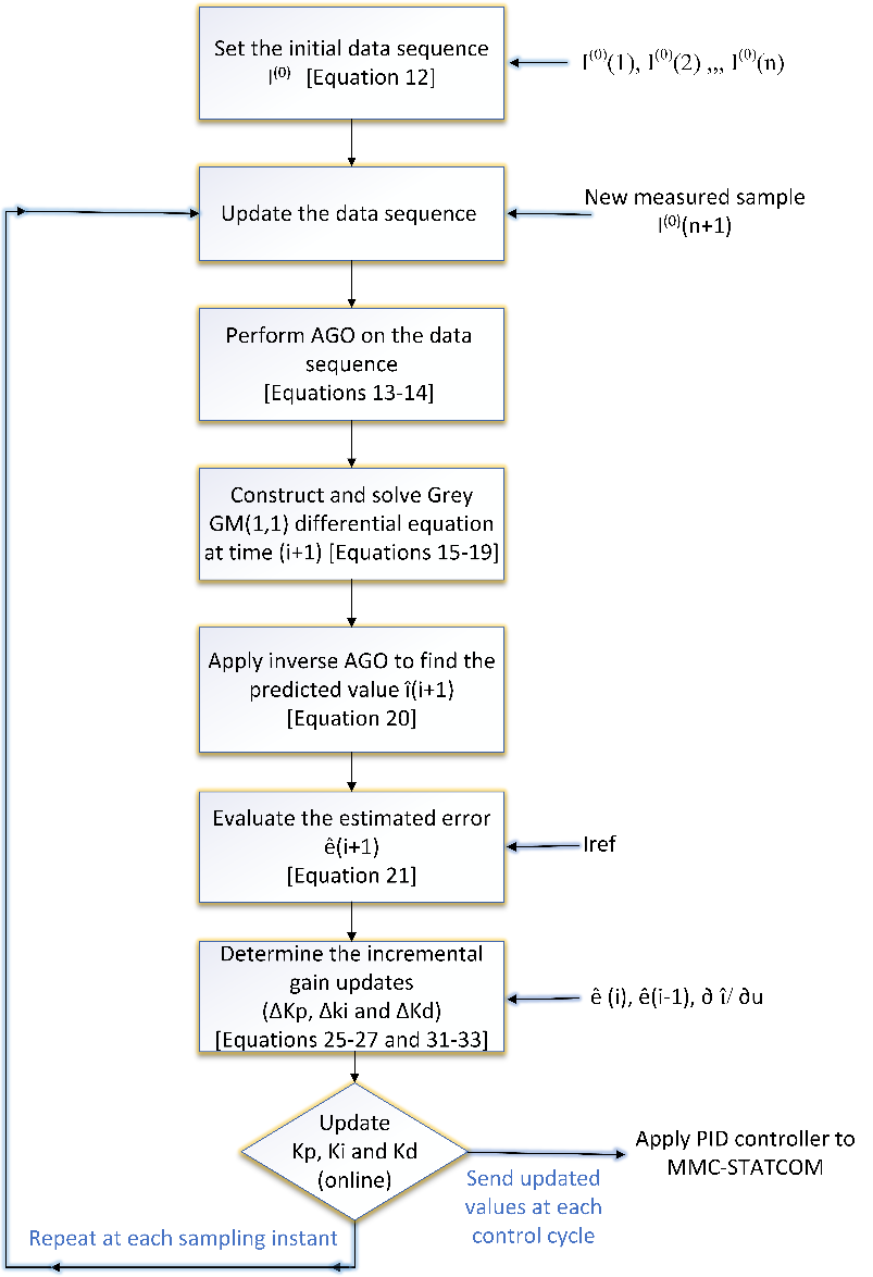
Figure 2. Flowchart of GM(1,1) model and gradient-descent algorithm (the symbol refers to the , or )
- SIMULATION OF MMC-STATCOM CONTROLLER
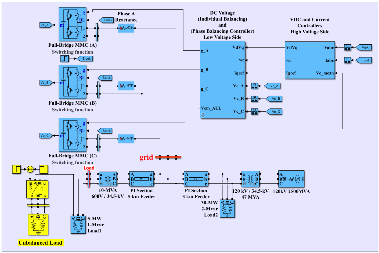
To verify the effectiveness of the proposed controller, a MATLAB/Simulink model of the adaptive grey-PID technique is implemented. Discrete Tustin/Background Euler solver is used with  sec. sampling time. General view of the power network with MMC-STATCOM is shown in Figure 3. This network consists of a three-phase 12 MVA, 34.5 kV distribution system integrated with an MMC-STATCOM. Each phase includes a full-bridge multilevel converter structure with 22 power modules per phase, connected through phase reactance to the grid [3]. Three loads are connected to the network, including an unbalanced load to test the dynamic and steady-state behavior of the controller under non-ideal conditions. The parameters of studied power system are tabulated in Table 2. The controllers divided into: High voltage side and Low voltage side [18]. The high voltage side is shown in Figure 4 and it consists of phase-locked loop, transformation block, DC voltage regulator, and currents ( and ) regulator.
Figure 3. General view of the power network with MMC-STATCOM\
Table 2. Parameters of the power network [3]
Parameter | Value | Parameter | Value |
Power capacity of the STATCOM | 12MVA | Transformer 1 | 120 kV/34.5 kV |
PCC voltage (RMS) | 34.5 kV | Transformer 2 | 34.5 /0.6 kV |
MMC per phase | 22 | Load 1 | 5 MW+1 Mvar |
DC link voltage | 1600 V | Load 2 | 30 MW+ 2Mvar |
System frequency | 60 Hz | Energy stored in the capacitors | 30 kJ/MVA |
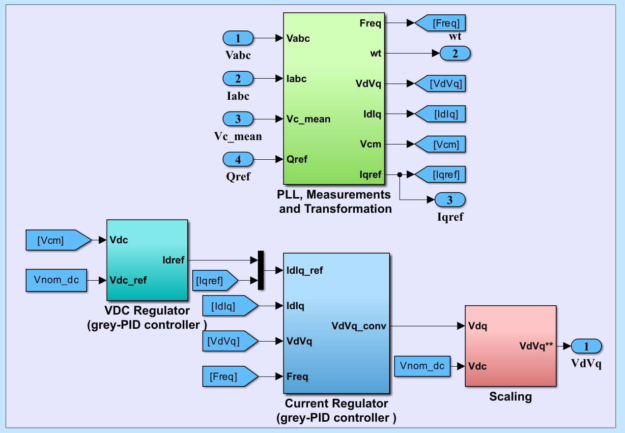
Figure 4. High voltage side controller
The phase-locked loop (PLL) is a precise estimator of the grid frequency and phase angle, ensuring that all control components such as the DC voltage regulator and current regulator operate within a synchronous reference frame aligned in both speed and phase with the grid. This synchronization facilitates decoupled control of active and reactive power and enhances the overall stability and dynamic performance of the controller, the PLL is shown in Figure 5. The DC-bus voltage regulator is shown in Figure 6, which employs an adaptive PID controller, the reference and measured DC voltages ( , ) are first normalized by the nominal DC voltage. The normalized values are then compared to generate the voltage error signal [19]. This error is processed by the controller; the controller output provides the reference direct-axis current
  for the inner current control loop.
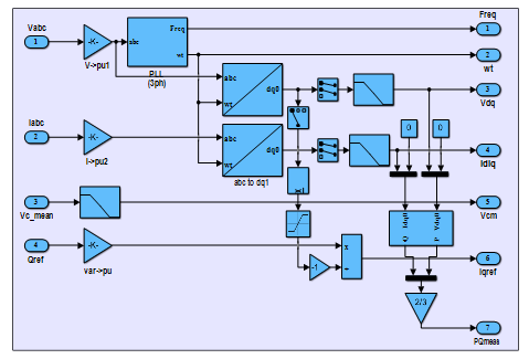
Figure 5. Phase-locked loop and transformation
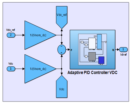
Figure 6. DC voltage-based adaptive grey -PID Controller
The current control is shown in Figure 7, and components are controlled separately by an adaptive PID control. The d-axis controller regulates to track , while the q-axis controller ensures accurate tracking of to  . The outputs of the controller generate the voltage commands
  and
and  , which are then used to drive the converter, enabling precise regulation of active and reactive power exchange with the grid. The adaption mechanism of the Grey-PID controller is achieved through the integration of three main modules: the grey prediction model, a numerical derivative estimation block, and a gradient-descent parameter adaptation scheme. The input error signal is processed by the adaptive block to continuously adjust the , , and gains of the PID controller. Figure 8 illustrates the detailed structure of the Grey- PID controller.
The numerical  unit computes the discrete-time derivatives of both the control signal () and the system output (y). These derivatives are then used to estimates the sensitivity of system output to changes in control input, which provides essential information for the gradient-descent adaptation law, Figure 9 illustrates the numerical unit. The mathematical model of the grey predictor is developed in m-file included in function block; Figure 10 illustrates the grey predictor.
The gradient-descent unit calculates the incremental updates,  ,
,  , and
, and  , the inputs of this unit are the present error and last two error signals, in addition to the estimated du/dy signal. The incremental updates are applied in real time to the PID gains, enabling the controller to maintain a fast transient response. Figure 11 and Figure 12 illustrate the gradient-descent unit and the adaptive PID, respectively. Low voltage side controller consists of phase balancing and individual balancing controllers of the DC bus voltage, that generate the appropriate gating signals for the converter switches [20]. Low voltage side controller is shown in Figure 13.
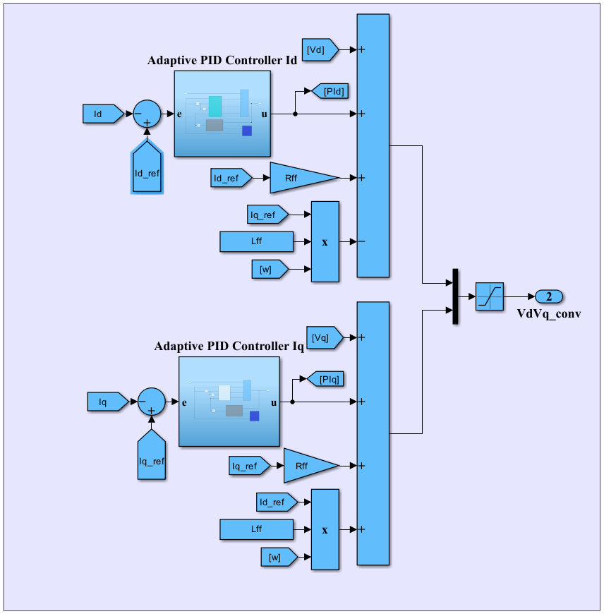
Figure 7. and Current controller
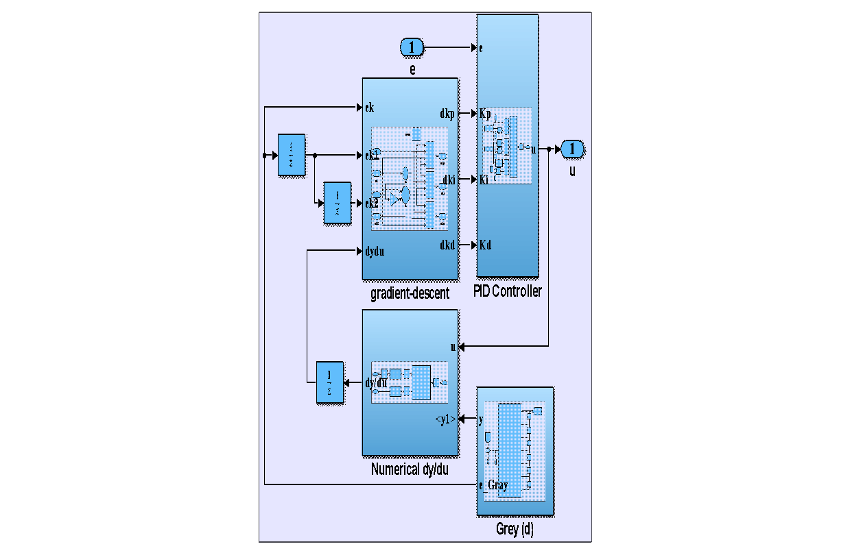
Figure 8. The configuration of adaptive grey-PID Controller
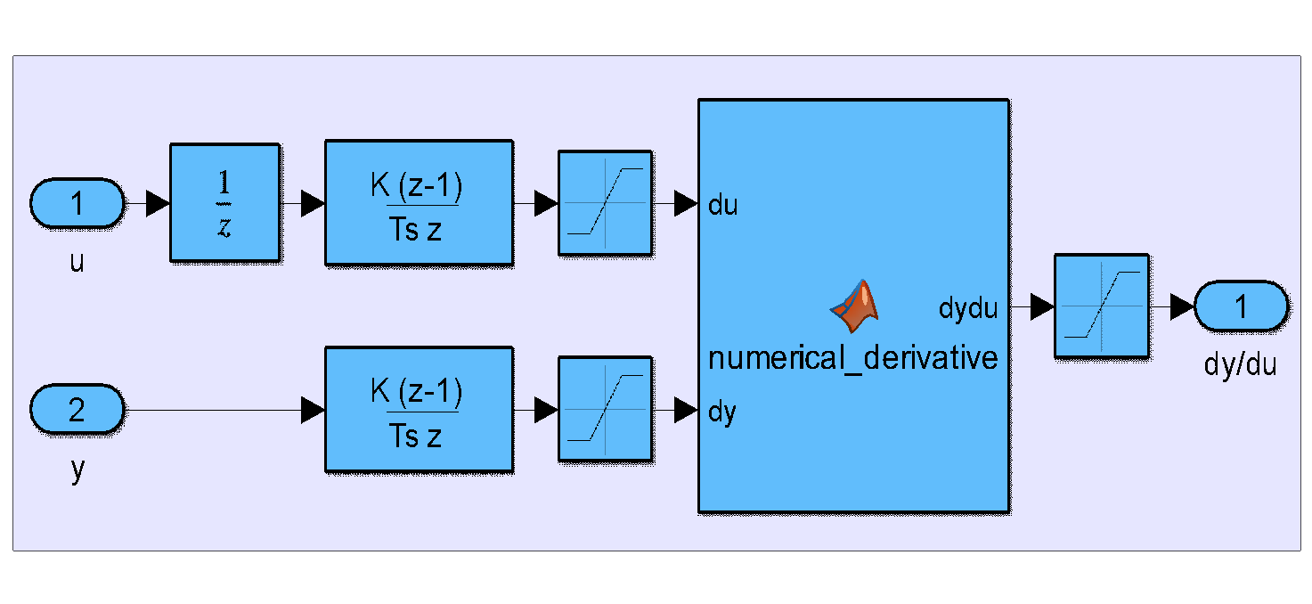
Figure 9. Numerical unit
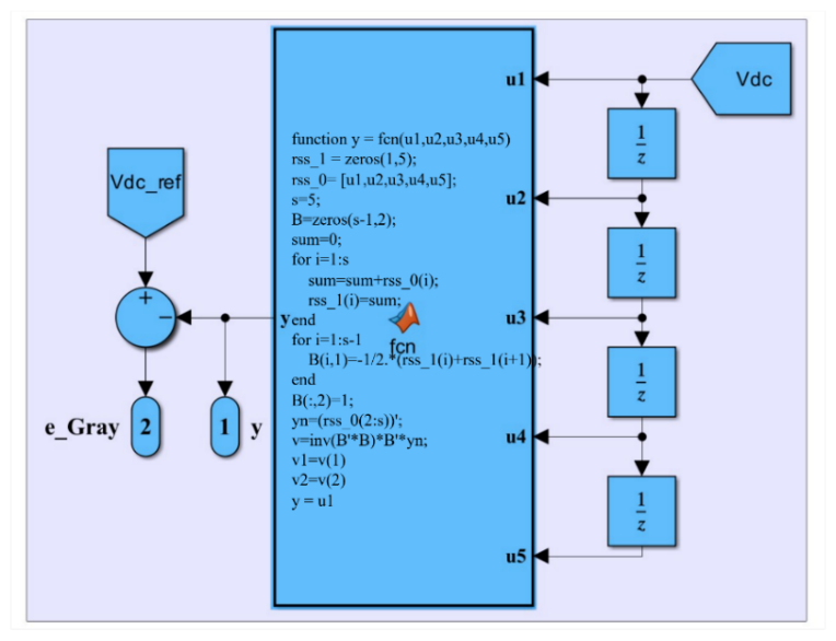
Figure 10. Grey predictor

Figure 11. gradient-descent model
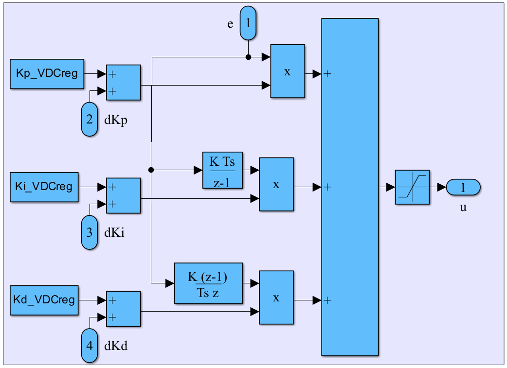
Figure 12. The adaptive PID Controller
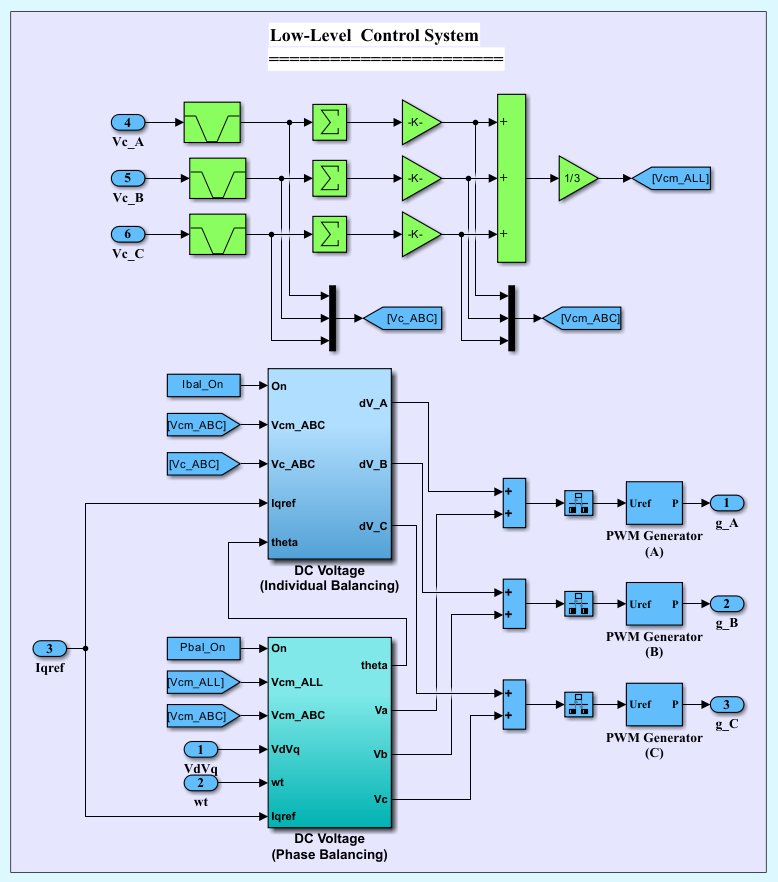
Figure 13. Low voltage side controller
- RESULT AND DISCUSSIONS
Initially, the reactive power command  of the MMC-STATCOM is set at −7 MVAr, at which the STATCOM operates in the inductive mode. At time instant 0.2 s, is stepped to +20 MVAr, in this case MMC-STATCOM will operate in capacitive mode. The performance of the STATCOM is evaluated under two operating scenarios: balanced-load and unbalanced-load conditions.
- Balanced Load Condition
The dynamic behavior of the capacitor voltages for selected sub-modules in phase Ais illustrated in Figure 14. It can be observed that effective voltage balancing during transient operating conditions is maintained with minimal deviation. Figure 15 illustrates that the DC-link voltages return to their steady-state values within a short period after the change occurring at 0.2 s. According to Figure 15(b), the DC-link voltage exhibits a maximum overshoot of approximately 1.25% and settles time is within 0.04 s. Moreover, the steady-state error is negligible, confirming the effectiveness of the proposed control strategy in maintaining DC-link voltage stability which effectively minimizes the circulating current.
THD of the grid current using a conventional PI controller is 19.47% as shown in Figure 16, which was then corresponding to an approximate reduction of 43.75% to 10.95% by utilizing the Grey-PID controller as shown in Figure 17. Grid side voltage and current are illustrated in Figure 18. When the reference reactive power set-point is altered at 0.2s, the grid current shifts from lagging to leading with respect to the grid voltage. The controller of the STATCOM provides a fast response by adjusting the converter terminal voltage to supply reactive power in capacitive mode. The current and voltage of the load are represented in Figure 19.
The active and reactive power of the MMC-STATCOM is shown in Figure 20. About-zero active power exchange is obvious, as the primary control objective is to regulate the grid voltage by injecting or absorbing reactive power and the required active power input from the grid is limited to cover the internal losses. Moreover, Figure 20 indicates that the reactive power exhibits a rapid dynamic response within about 0.04s settling time.
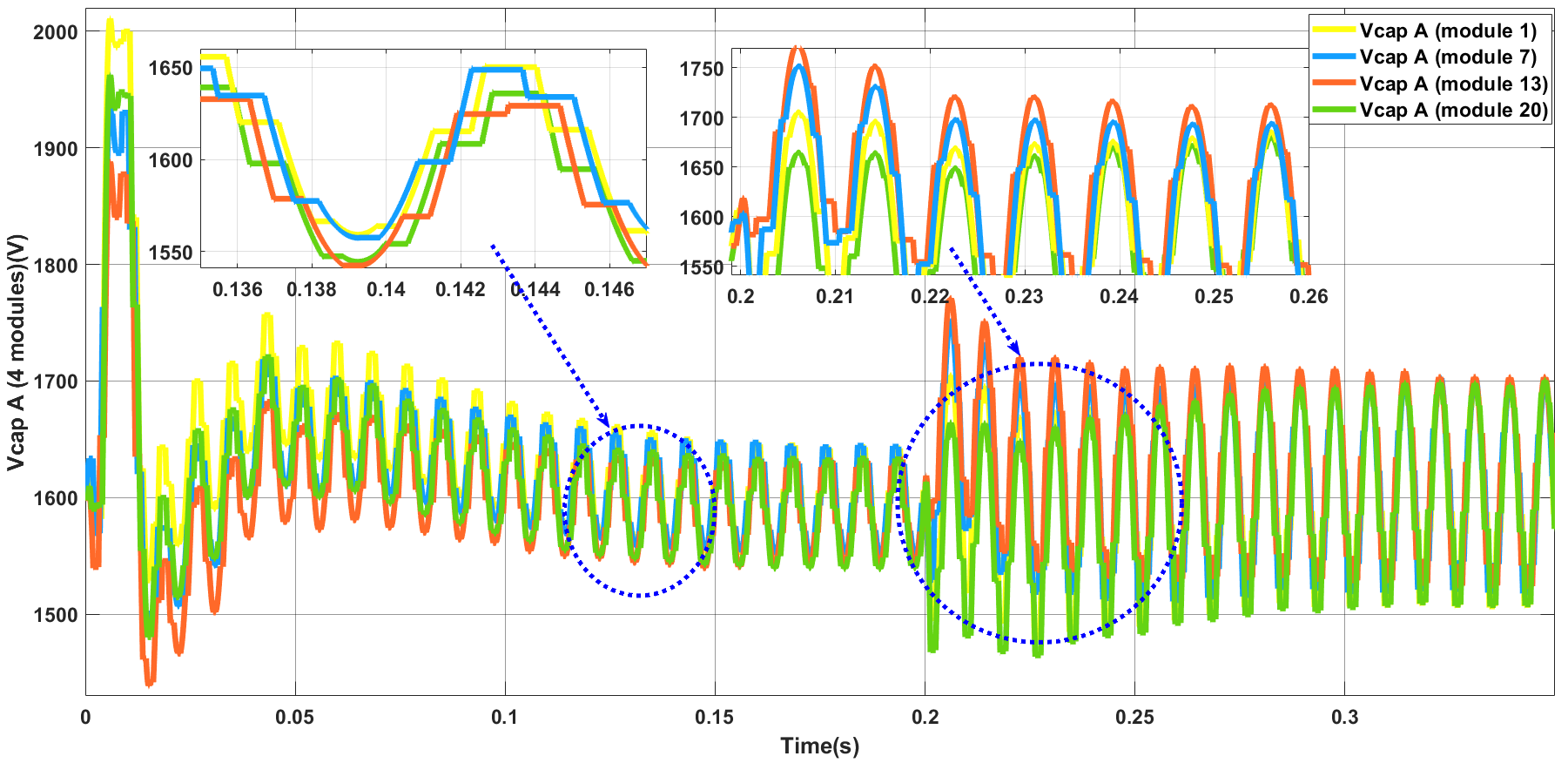
Figure 14. Response of phase-A capacitor voltages (sub-module 1, 7, 13 and 20) during transient condition
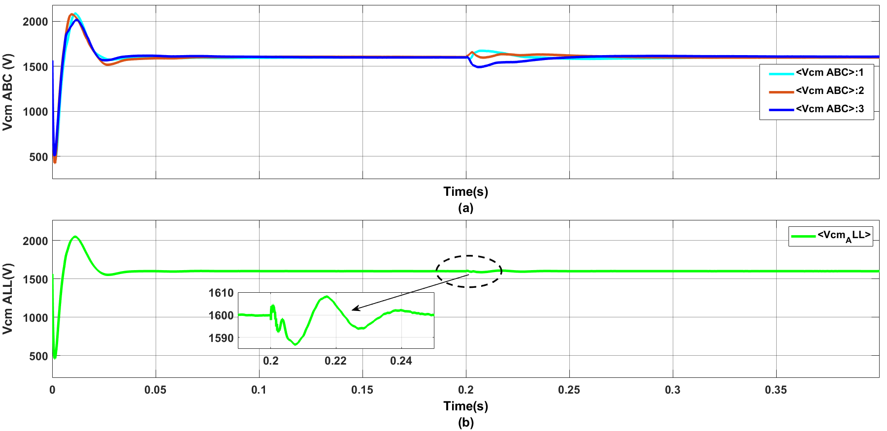
Figure 15. DC-link voltage during dynamic operating condition (a) Capacitor voltages of phases A, B, and C, (b) Average value
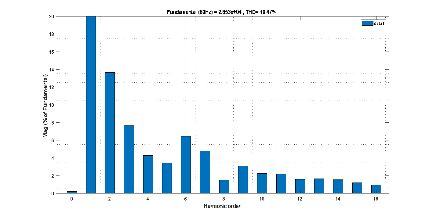
Figure 16. THD analysis of the grid current using PI controller
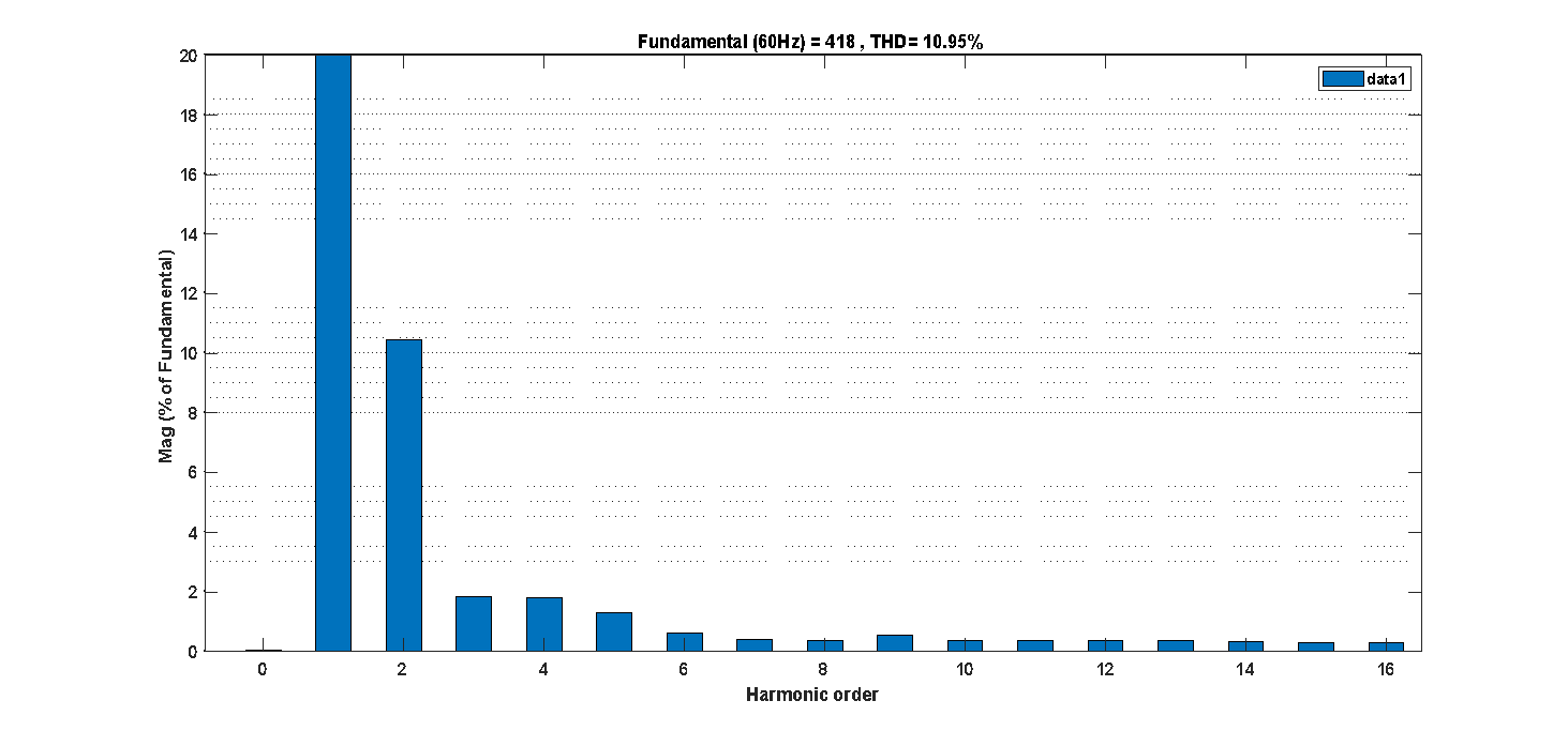
Figure 17. THD analysis of the grid current using Grey-PID controller
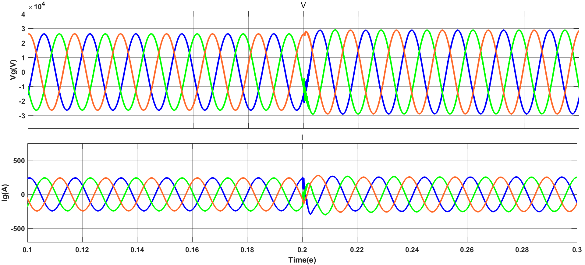
Figure 18. Voltage and current at grid side
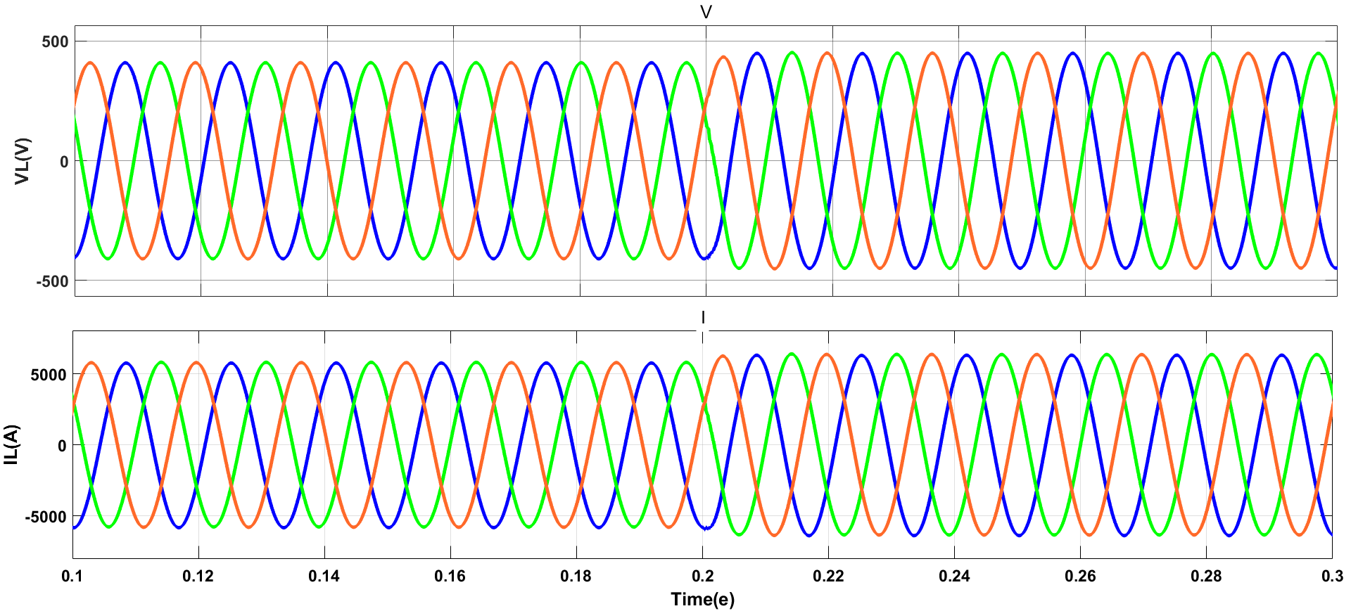
Figure 19. Voltage and current of the load
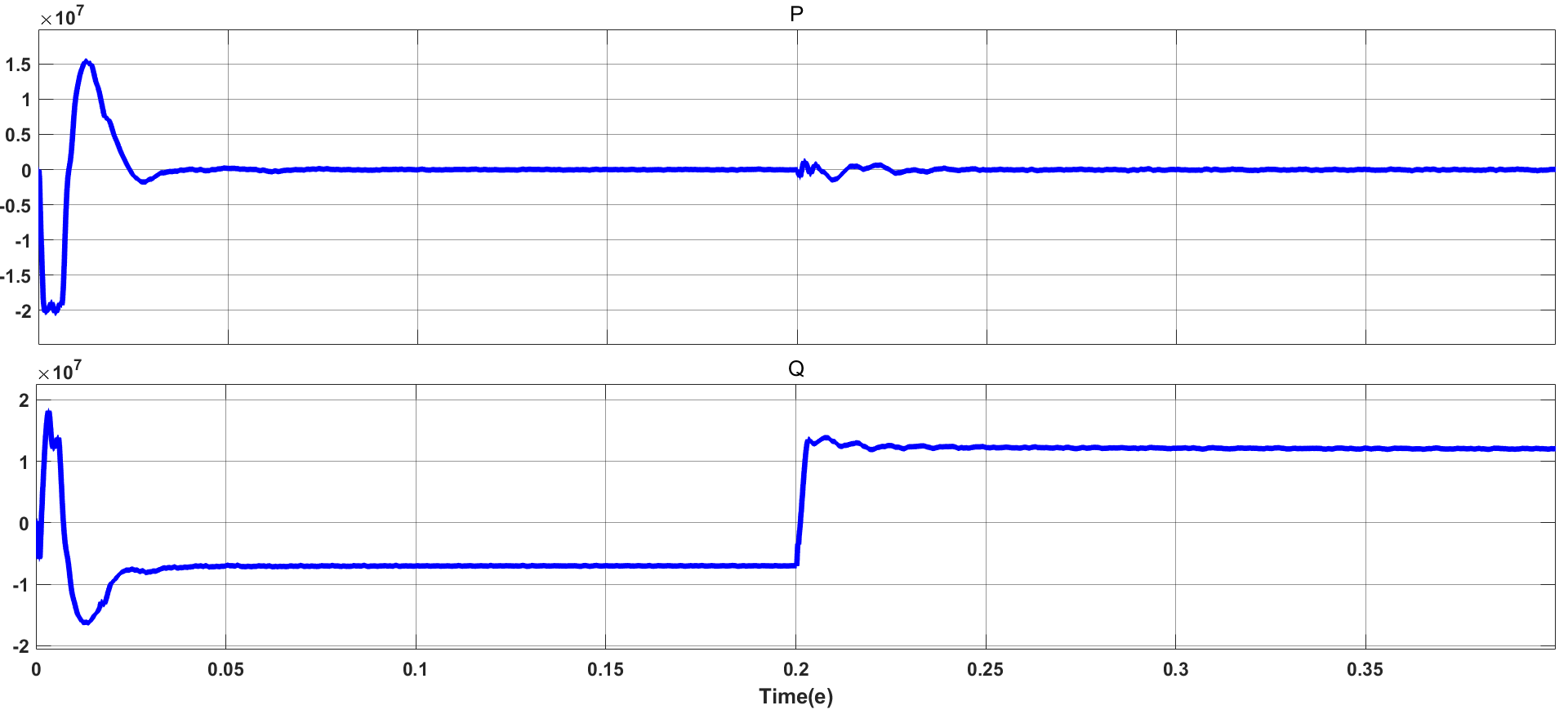
Figure 20. Reactive and active power of the STATCOM
- Unbalanced Load Condition
In this scenario, a severe unbalanced condition was created by adding an approximately 25% inductive load to phase A. The unbalance voltage and current at load side are illustrated in Figure 21. The unbalance voltage and current at grid side without MMC-STATCOM are displayed in Figure 22. The effectiveness of the grey-PID controller is demonstrated as it successfully restores the balance to the grid voltage and current. This regulation entailed a rise in the grid current, driven by the injection of the necessary reactive current component as shown in Figure 23.
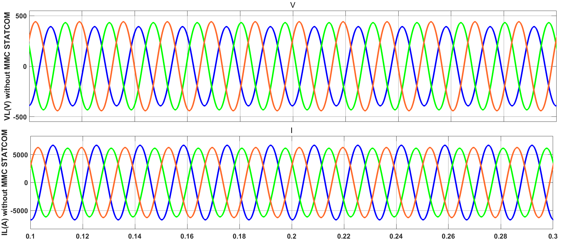
Figure 21. Load voltage and load current with an unbalanced load condition
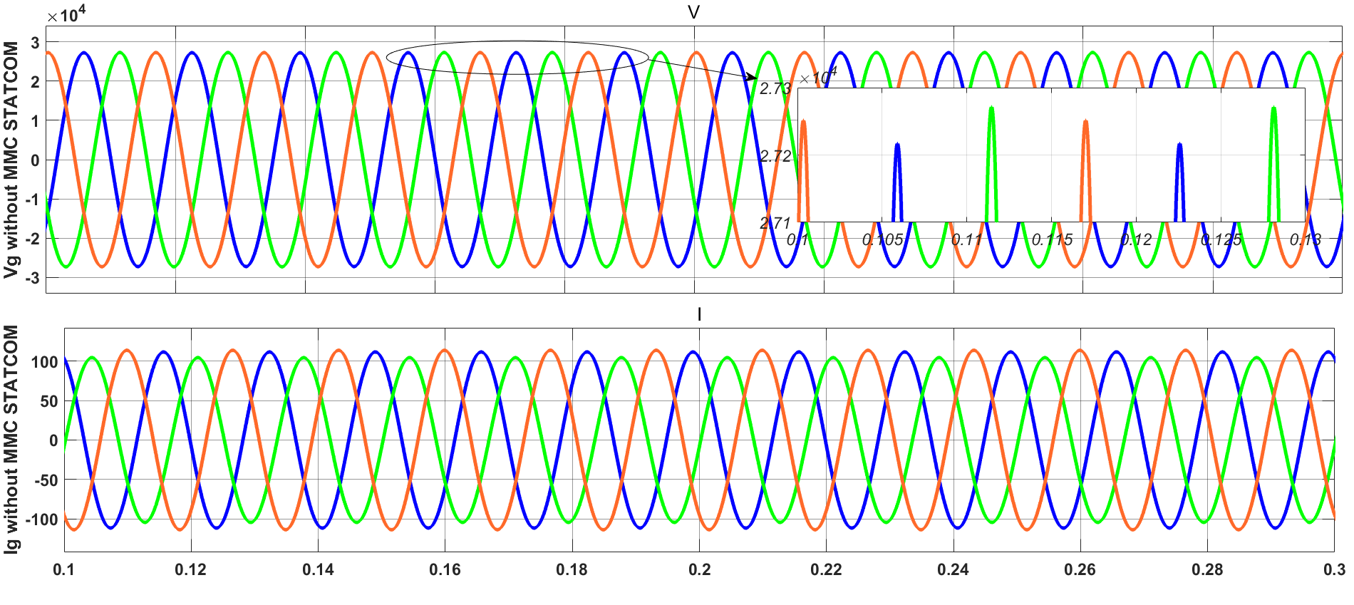
Figure 22. Grid voltage and grid current with unbalanced load condition (without STATCOM)
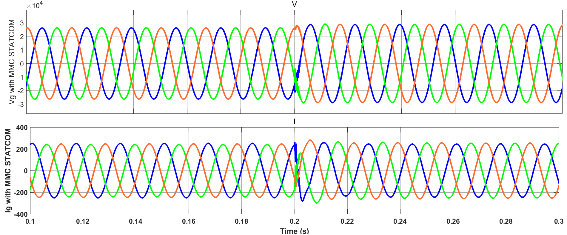
Figure 23. Grid voltage and grid current with unbalanced load condition (with STATCOM)
The DC-link voltage of the MMC under unbalanced load condition is shown in Figure 24, the proposed control system maintained the DC voltage at constant level without fluctuations. it is clearly noted that the DC voltages return to the steady-state rapidly after the instant 0.2 s. This could only be achieved by increasing the grid current due to an increase in reactive current. The THD of grid current using PI controller is 20.79% as shown in Figure 25, while the THD is reduced by 33.42% to be 13.84% with Grey-PID as shown in the Figure 26. Table 3 presents a comparative analysis between the performance of the proposed controller in this paper and other existing techniques reported in the literature. From Table 3, it is evident that the proposed controller achieves favorable results compared to most existing techniques.
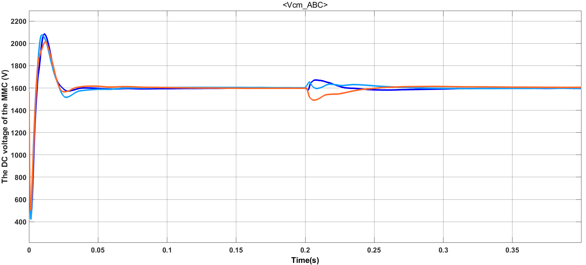
Figure 24. The DC-link voltage of MMC with an unbalanced load condition
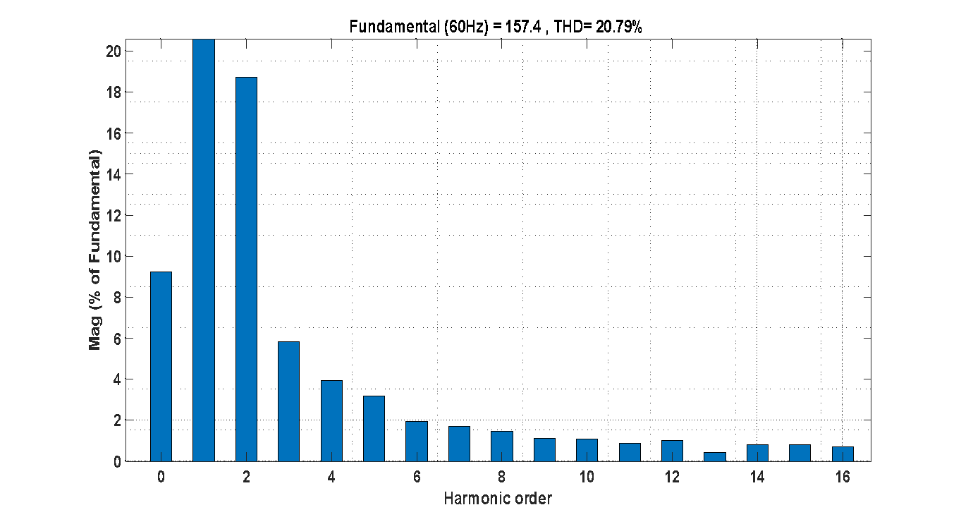
Figure 25. The THD of grid current with an unbalanced load using PI controller
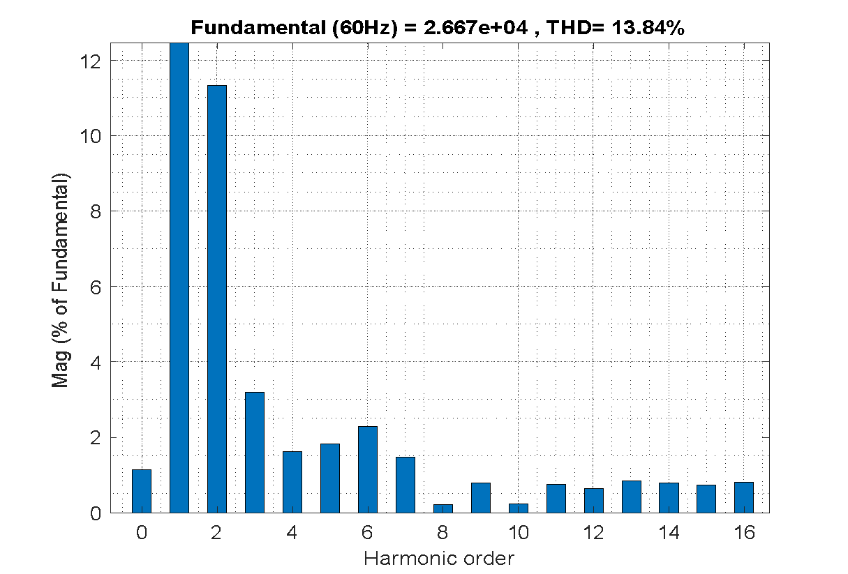
Figure 26. THD of grid current at unbalance load using grey-PID controller
Table 3. Comparative analysis of related works
Reference | Compared technique | Evaluation focus | Key comparative outcome |
[43] | PI-MPC,  -MPC and 2DOF PI-MPC -MPC and 2DOF PI-MPC | DC-link overshoot and settling time | those methods exhibit large DC-link overshoot (7.27-7.72 %) with settling times of 0.16–0.17s, whereas the proposed Grey-PID achieves 1.25% overshoot and faster settling (0.04 s), demonstrating superior transient regulation. |
[44] | Review of STATCOM Controls | Adaptability to Grid Dynamics | The review concludes that fixed-gain controllers fail under transient conditions; Grey-PID addresses this gap by offering real time adaptation with low computational complexity. |
[45] | FFSMC D-STATCOM | Control smoothness | Fixed-frequency sliding mode control introduces significant chattering, while the Grey-PID ensures smooth control action. |
[46] | Cuttlefish-Optimized PI | DC-link voltage overshoot | This controller exhibits DC-link overshoot of 2.85% after load variation, whereas proposed controller maintains low overshoot=1.25%, indicating enhanced transient stability. |
[47] | Adaptive DSCC-STATCOM | Dynamic Response Speed | In this approach, the system settles in about 0.05 s, while Grey-PID achieves a superior settling time of 0.04 s, demonstrating faster transient recovery. |
[48] | Fuzzy Logic-PI based STATCOM | DC-link transient behavior | Fuzzy-PI is evaluated under fault conditions without presenting DC-link transient behavior. In contrast, the proposed controller explicitly ensures stable DC-link voltage and rapid dynamic response under balanced and unbalanced operating conditions.
|
[49] | APSO-Optimized PI | Dynamic regulation and stability | Performance is evaluated indirectly via IAE convergence without explicit DC-link transient results, while Grey-PID directly demonstrates near-zero overshoot, faster settling, and improved current quality. |
[50] | Fractional-Order PI - based STATCOM | Settling time | This method achieved a settling time of 0.2 s. However, the proposed approach achieves a superior settling time, ensuring rapid system restoration |
- CONCLUSIONS
This paper proposed a new adaptive PID controller supported by a grey prediction model for MMC-based STATCOM systems. The core contribution lies in the integration of the grey model, which predicts error values, enabling the on-line updated PID controller to achieve rapid dynamic system response and low grid current harmonic distortion compared to the conventional PI controller. The eligibility of the proposed controller was validated through comprehensive simulation tests on a 12 MVA, 34.5 kV distribution system featuring a full-bridge MMC topology. Under balanced load condition, the adaptive grey-PID controller demonstrated a significant superior performance over the conventional PI controller, and the THD of grid current was reduced from 19.47% to 10.95%, corresponding to a reduction of about 43.75%. When the system is subjected to an unbalanced load, the suggested controller successfully restored balance in the grid voltage and current. Moreover, reduced the THD of the grid current from 20.79% to 13.84%, representing a reduction of about 33.42%. The lower THD reduction observed under unbalanced load is mainly attributed to the presence of negative-sequence current components and increased current stress caused by load asymmetry, which inherently limits harmonic mitigation performance. Crucially, the controller maintained a stable and constant DC-link voltage under both balanced and unbalanced load conditions, which effectively enhances the overall stability and the performance of the MMC. In conclusion, the prediction and adaptation capabilities of the proposed control strategy considerably enhance the dynamic and steady-state performance of the MMC-STATCOM system. For future work, the proposed controller could be tested experimentally using a hardware setup like FPGA board to confirm the simulation results and evaluate its performance in real-time applications.
DECLARATION
Author Contribution
All authors contributed equally to this paper. All authors read and approved the final paper.
Funding
The authors received no specific funding for this work.
Conflicts of Interest
The authors have no conflict of interest to declare.
REFERENCES
- B. R. Andersen and S. L. Nilsson, Flexible AC Transmission Systems (FACTS). Switzerland: Springer Nature, 2020, https://doi.org/10.1007/978-3-030-35386-5.
- F. Shahnia, S. Rajakaruna, and A. Ghosh, Eds., Static Compensators (STATCOMs) in Power Systems, vol. 735. Singapore: Springer Singapore, 2015, https://doi.org/10.1007/978-981-287-281-4.
- D. Sarathkumar et al., "Power system stability enhancement in two machine system by using fuel cell as STATCOM (static synchronous compensator)," Materials Today: Proceedings, vol. 45, pp. 2130-2138, 2021, https://doi.org/10.1016/j.matpr.2020.09.730.
- A. Mandal et al., "A novel architecture of the solid-state unified power flow controller and its integration into the power grid," Electric Power Systems Research, vol. 241, p. 111296, 2025, https://doi.org/10.1016/j.epsr.2024.111296.
- V. Shukla, V. Mukherjee, and B. Singh, "Integration of distributed generations and static var compensators with static synchronous compensators to reduce power losses," Engineering Applications of Artificial Intelligence, vol. 126, p. 107208, 2023, https://doi.org/10.1016/j.engappai.2023.107208.
- S. M. Lamine, B. Soltane, and N. A. L. Ahmed, "Improved voltage regulation using fuzzy logic-based static synchronous compensator controllers with stacked multi-cell multi-level inverter in modern power grids," Energy Reports, vol. 14, pp. 3286-3297, 2025, https://doi.org/10.1016/j.egyr.2025.10.017.
- M. H. Haque, "Damping improvement by FACTS devices: A comparison between STATCOM and SSSC," Electric Power Systems Research, vol. 76, no. 9-10, pp. 865-872, 2006, https://doi.org/10.1016/j.epsr.2005.11.001.
- X.-P. Zhang, E. Handschin, and M. Yao, "Multi-control functional static synchronous compensator (STATCOM) in power system steady-state operations," Electric Power Systems Research, vol. 72, no. 3, pp. 269-278, 2004, https://doi.org/10.1016/j.epsr.2004.04.011.
- R. O. de Sousa et al., "Life consumption of a MMC-STATCOM supporting wind power plants: Impact of the modulation strategies," Microelectronics Reliability, vol. 88, pp. 1063-1070, 2018, https://doi.org/10.1016/j.microrel.2018.06.111.
- K. Xu et al., "Disturbed optimal power flow with renewable source and static synchronous compensator," Expert Systems with Applications, vol. 295, p. 128799, 2025, https://doi.org/10.1016/j.eswa.2025.128799.
- J. V. M. Farias et al., "Redundancy design for modular multilevel converter based STATCOMs," Microelectronics Reliability, vol. 100, p. 113471, 2019, https://doi.org/10.1016/j.microrel.2019.06.012.
- J. Maeng et al., "A supercapacitor size minimization and energy management strategy for E-STATCOM connected to weak grid," International Journal of Electrical Power & Energy Systems, vol. 172, p. 111174, 2025, https://doi.org/10.1016/j.ijepes.2025.111174.
- P. Hu, J. M. Guerrero, and Z. He, "Design and analysis of a transformerless STATCOM based on hybrid cascaded multilevel converter," International Journal of Electrical Power & Energy Systems, vol. 104, pp. 694-704, 2019, https://doi.org/10.1016/j.ijepes.2018.07.059.
- Y. Liu et al., "MMC-STATCOM supplementary wide-band damping control to mitigate sub-synchronous control interaction in wind farms," International Journal of Electrical Power & Energy Systems, vol. 141, p. 108171, 2022, https://doi.org/10.1016/j.ijepes.2022.108171.
- M. Humayun et al., "Analysis of hybrid switches symmetric flying capacitor multilevel inverter based STATCOM," International Journal of Electrical Power & Energy Systems, vol. 131, p. 107054, 2021, https://doi.org/10.1016/j.ijepes.2021.107054.
- S. N. Duarte, P. G. Barbosa, and E. Kabalcı, "STATCOM and DSTATCOM with modular multilevel converters," in Multilevel Inverters: Control Methods and Advanced Power Electronic Applications, p. 209, 2021, https://doi.org/10.1016/B978-0-12-821206-6.00006-X.
- R. O. de Sousa et al., "Wear-out failure analysis of modular multilevel converter-based STATCOM: The role of the modulation strategy and IGBT blocking voltage," Microelectronics Reliability, vol. 128, p. 114426, 2022, https://doi.org/10.1016/j.microrel.2021.114426.
- K. Sayahi and F. Bacha, "STATCOM-Active power filter improved hysteresis current control for power quality management under unbalanced and distorted grid voltage," Results in Engineering, vol. 27, p. 107064, 2025, https://doi.org/10.1016/j.rineng.2025.107064.
- M. L. Srief et al., "A complete control structure based backstepping controller design for stacked multi-cell multi-level SPWM VSC STATCOM," Energy Reports, vol. 12, pp. 687-698, 2024, https://doi.org/10.1016/j.egyr.2024.06.051.
- A. A. Z. Diab et al., "Optimal design and control of MMC STATCOM for improving power quality indicators," Applied Sciences, vol. 10, no. 7, p. 2490, 2020, https://doi.org/10.3390/app10072490.
- A. Stepanov, H. Saad, and J. Mahseredjian, "Modeling of MMC-based STATCOM with embedded energy storage for the simulation of electromagnetic transients," Electric Power Systems Research, vol. 220, p. 109316, 2023, https://doi.org/10.1016/j.epsr.2023.109316.
- F. Eroğlu et al., "Multi-objective control strategy for multilevel converter-based battery D-STATCOM with power quality improvement," Applied Energy, vol. 341, p. 121091, 2023, https://doi.org/10.1016/j.apenergy.2023.121091.
- X. Liu et al., "DBS-less MMC-MTDC system integrating large-scale offshore wind power," Electric Power Systems Research, vol. 244, p. 111589, 2025, https://doi.org/10.1016/j.epsr.2025.111589.
- R. Raj et al., "Critical review of hybrid modular multilevel converters for HVDC transmission in offshore wind energy," Energy Reports, vol. 14, pp. 1761-1778, 2025, https://doi.org/10.1016/j.egyr.2025.07.017.
- A. Bharadwaj and S. Maiti, "Multilevel converter-based STATCOM with hybrid storage system," in Emerging Trends in Energy Storage Systems and Industrial Applications, pp. 521-534, 2023, https://doi.org/10.1016/B978-0-323-90521-3.00012-0.
- A. Dekka et al., "Modular multilevel converters," in Multilevel Inverters, pp. 147-179, 2021, https://doi.org/10.1016/B978-0-12-821206-6.00004-6.
- S. K. Chaudhary et al., "Benchmarking of modular multilevel converter topologies for ES-STATCOM realization," Energies, vol. 13, no. 13, p. 3384, 2020, https://doi.org/10.3390/en13133384.
- S. N. Duarte, P. M. Almeida, and P. G. Barbosa, "Voltage regulation of a remote microgrid bus with a modular multilevel STATCOM," Electric Power Systems Research, vol. 212, p. 108299, 2022, https://doi.org/10.1016/j.epsr.2022.108299.
- S. N. Duarte et al., "Experimental evaluation of negative-sequence voltage compensation in distribution networks by a modular multilevel static synchronous compensator," Electric Power Systems Research, vol. 194, p. 107020, 2021, https://doi.org/10.1016/j.epsr.2021.107020.
- J. K. Bhutto, “An adaptive controlled STATCOM and SMES for LVRT augmentation of the renewable integrated AC-microgrid,” Heliyon, vol. 11, no. 3, p. e42326, 2025, https://doi.org/10.1016/j.heliyon.2025.e42326.
- R. S. Camargo et al., "Novel multilevel STATCOM for power system stability enhancement on DFIG-based wind farms," Electric Power Systems Research, vol. 197, p. 107316, 2021, https://doi.org/10.1016/j.epsr.2021.107316.
- J. Inwumoh, C. Baguley, and K. Gunawardane, "A dynamic control methodology for DC fault ride through of modular multilevel converter based high voltage direct current systems," Computers and Electrical Engineering, vol. 100, p. 107940, 2022, https://doi.org/10.1016/j.compeleceng.2022.107940.
- A. Bharadwaj et al., "E-STATCOM (energy storage+ STATCOM): A solution to integrate large-scale wind farms into the grid at medium and high-power levels," in Power Quality in Modern Power Systems, pp. 283-310, 2021, https://doi.org/10.1016/B978-0-12-823338-2.00008-5.
- P. Sah and B. K. Singh, "Power quality improvement using distribution static synchronous compensator," Computers and Electrical Engineering, vol. 106, p. 108599, 2023, https://doi.org/10.1016/j.compeleceng.2023.108599.
- C. Liao et al., "Small-signal model-based stability analysis for single-phase cascaded H-bridge STATCOM considering time delay," International Journal of Electrical Power & Energy Systems, vol. 157, p. 109880, 2024, https://doi.org/10.1016/j.ijepes.2024.109880.
- R. C. Panda, Ed., Introduction to PID controllers: theory, tuning and application to frontier areas. InTech, 2012, https://doi.org/10.5772/2422.
- K. Chen, B. Xiao, C. Wang, X. Liu, S. Liang, and X. Zhang, “Cuckoo coupled improved grey wolf algorithm for PID parameter tuning,” Applied Sciences, vol. 13, no. 23, p. 12944, 2023, https://doi.org/10.3390/app132312944.
- J. Zhang, Y. Qin, X. Zhang, G. Che, X. Sun, and H. Duo, “Application of non-equidistant GM (1, 1) model based on the fractional-order accumulation in building settlement monitoring,” Journal of Intelligent & Fuzzy Systems, vol. 42, no. 3, pp. 1559-1573, 2022, https://doi.org/10.3233/JIFS-210936.
- C. C. Tong and E. Barbieri, "Design of refined grey prediction controller," in Proc. IEEE International Conference on Systems, Man and Cybernetics, pp. 1-6, 2006, https://doi.org/10.1109/ICSMC.2006.384351.
- L. Hou, X. Li, and M. Wang, "Grey-fuzzy PI optimal control of MMC-HVDC system," in Proc. IEEE 4th Conference on Energy Internet and Energy System Integration (EI2), pp. 1-6, 2020, https://doi.org/10.1109/EI250167.2020.9347162.
- C. Hsu et al., "An auto-tuning PID regulator using grey predictor," in Proc. IEEE Conference on Cybernetics and Intelligent Systems, pp. 1-6, 2006, https://doi.org/10.1109/ICCIS.2006.252277.
- Q. Li and Y. Lin, "Review paper: A Briefing to Grey Systems Theory," Journal of Systems Science and Information, vol. 2, no. 2, pp. 178-192, 2014, https://doi.org/10.1515/JSSI-2014-0178.
- O. Ö. Mengi, "Comparison of MPC based advanced hybrid controllers for STATCOM in medium scale PEM fuel cell systems," International Journal of Hydrogen Energy, vol. 45, no. 43, pp. 23327-23342, 2020, https://doi.org/10.1016/j.ijhydene.2020.06.071.
- H. Fretes et al., "Analysis of a delta modular multilevel converter for E-STATCOM applications," IEEE Transactions on Power Delivery, vol. 40, no. 6, pp. 3106-3117, 2025, https://doi.org/10.1109/TPWRD.2025.3606853.
- T T. Ahmed, A. Waqar, S. Haider and A. Armghan, "Application of Fixed Frequency Sliding Mode Control for D-STATCOM in Power Systems," 2021 International Bhurban Conference on Applied Sciences and Technologies (IBCAST), Islamabad, Pakistan, 2021, pp. 524-529, 2021, https://doi.org/10.1109/IBCAST51254.2021.9393248.
- E. Ramakrishna, J. Gadhamappagari, and P. Sujatha, "Auto tuning of PI Gains using Cuttlefish Optimization for DC Link Voltage Control in a 5-level HB MMC D-STATCOM," Engineering, Technology & Applied Science Research, vol. 13, no. 6, pp. 12086-12091, 2023, https://doi.org/10.48084/etasr.6413.
- J. Girona-Badia et al., “Design, control and testing of a modular multilevel converter with a single cell per arm in grid-forming and grid-following operations for scaled-down experimental platformsm,” Energies, vol. 15, no. 5, p. 1819, 2022, https://doi.org/10.3390/en15051819.
- I. Y. Fawzy et al., "Deployment of STATCOM with fuzzy logic control for improving the performance of power system under different faults conditions," Journal of Robotics and Control (JRC), vol. 5, no. 3, pp. 636-646, 2024, https://doi.org/10.18196/jrc.v5i3.21558.
- Y. Hamad, "Optimization of Controller Parameter Multilevel Converter Based STATCOM for Reactive Power Compensation," Researcher, vol. 4, no. 1, pp. 29-40, 2024, https://izlik.org/JA37PX82CH.
- A. Umar, "Stability Improvement of STATCOM System Using Fractional-Order Proportional Integral (FOPI) Based Control Strategies," Bayero Journal of Engineering and Technology, vol. 20, no. 1, pp. 44-53, 2025, https://bjet.ng/index.php/jet/article/view/74.
Mohammed Moanes Ezzaldean Ali (Design of MMC-STATCOM Controller Using an Adaptive PID Controller Supported by a Grey Model)