ISSN: 2685-9572 Buletin Ilmiah Sarjana Teknik Elektro
Vol. 8, No. 1, February 2026, pp. 331-343
Indirect Matrix Converter Based Synchronous Reluctance Motor Drive Systems using Model Predictive Control
Nur Vidia Laksmi B. 1, Muhammad Syahril Mubarok 2,6,7, Widi Aribowo 1, Didik Purwanto 3,
Jacob Raglend Isaac 4, Vugar Hacimahmud Abdullayev 5
1 Electrical Engineering, Faculty of Vocational Studies, Universitas Negeri Surabaya, Indonesia
2 Electrical Engineering, Faculty of Advanced Technology and Multidiscipline, Universitas Airlangga, Indonesia
3 Delta Research Center, Delta Electronics Inc., Republic of China (ROC), Taiwan
4 School of Electrical Engineering, Vellore Institute of Technology, Vellore, India
5 Department of Computer Engineering, Azerbaijan State Oil and Industry University, Baku, Azerbaijan
6 Electrical Engineering, Renewable & Sustainable Energy Technology Research Group,
Universitas Airlangga, Indonesia
7 Research Center for New and Renewable Energy Engineering, Universitas Airlangga, Indonesia
ARTICLE INFORMATION |
| ABSTRACT |
Article History: Received 06 November 2025 Revised 16 Februari 2026 Accepted 12 March 2026 |
| 
This paper proposes a speed control strategy of Synchronous Reluctance Motors (SynRM) using an Indirect Matrix Converter (IMC) combined with a finite model predictive speed control (MPSC) and PI current control. This control algoritm is chosen than fully PI in both loops due to improve overall system stability and dynamic response. The IMC architecture offers advantages such as compactness, bidirectional power flow, and the elimination of bulky passive components, making it ideal for efficient motor drive systems. The proposed control method employs predictive algorithm using augmented state variable and cost function minimization technique. In addition, PI controllers here using a pole-assignment method. Both proposed controls aim to guarantee stability and responsiveness for dynamic performances. The MATLAB/Simulink is used here to simulate the system, incorporating practical motor parameters and space vector modulation techniques. Simulation results show that the control algorithm attains satisfactory speed performance, with minimal steady-state error 0.47%, overshoot below 2%, and fast settling time under various load 0.035 seconds and speed profiles. Additionally, the system performs robustly under reversed and sinusoidal speed commands, demonstrating its effectiveness and suitability for real-world industrial applications also need to implement in the experiment for the future works. |
Keywords: SynRM; Indirect Matrix Converter; Model Predictive Controller; Augmented State Variable; Cost Function |
Corresponding Author: Nur Vidia Laksmi B., Faculty of Vocational Studies, Universitas Negeri Surabaya, Surabaya, Indonesia. nurvidialaksmi@unesa.ac.id |
This work is licensed under a Creative Commons Attribution-Share Alike 4.0 
|
Document Citation: N. V. Laksmi B., M. S. Mubarok, W. Aribowo, D. Purwanto, J. R. Isaac, and V. H. Abdullayev, “Indirect Matrix Converter based Synchronous Reluctance Motor Drive Systems using Model Predictive Control,” Buletin Ilmiah Sarjana Teknik Elektro, vol. 8, no. 1, pp. 331-343, 2026, DOI: 10.12928/biste.v8i1.15222. |
- INTRODUCTION
As modern industries drive for greater energy efficiency and cleaner power, there is growing interest in advanced power electronic converters [1]-[7]. One technology drawing attention is the matrix converter that become promising alternative to conventional back-to-back converters. Matrix converters offer many advantages including eliminating bulky reactive components, enabling inherent bidirectional power flow, boosting reliability, and achieving compact designs [8]-[12]. Given these advantages, matrix converters are commonly used in many fields, such as motor drives [13]-[17] and grid integration [17]-[22]. The matrix converter, which evolved from forced commutated cycloconverters, has undergo extensive research for over three decades. The use of matrix converters is increasing in wind turbines and other applications where the device needs to supply and receive energy from both the generator and the grid [23]-[26]. Matrix converters, which directly convert AC to AC without intermediate DC-link stages, have gained traction as an alternative to traditional inverter-based AC drives [6]. These all-silicon solutions connect a voltage source directly to a load through controlled bidirectional power switches, doing away with the need for DC-link capacitors or inductors [27]-[30].
One of the common applications of matrix converters is in driving synchronous motors, specifically permanent magnet synchronous motors which have numerous benefits, including high power density and efficiency [31]-[35]. To achieve the best performance, matrix converters need advanced control schemes that can handle their complex switching behaviours and ensure stable operation of the synchronous motor. AC motors, including both induction and synchronous types, are essential in many industrial applications, including electric vehicles and robotics [36]. Combining matrix converters with synchronous motors creates a powerful synergy, resulting in drive systems with exceptional performance and energy efficiency [37]. In recent years, notable progress has been made in refining both the control strategies and design topologies of matrix converters used in synchronous motor drive applications. The matrix converter consists of actively controlled semiconductor devices and operates without the use of significant passive components. The minimization of passive components allows the matrix converter a topology primarily reliant on power semiconductor devices. Consequently, it offers exceptionally high power density, making it particularly well-suited for size and weight-sensitive applications such as aerospace, military systems, electric traction, and power distribution. The primary function of a matrix converter is to convert one AC voltage system to another, accommodating arbitrary amplitude, frequency, and number of phases [38]. To ensure bidirectional operation, matrix converters are built using bidirectional power semiconductor switches. However, the absence of magnets also makes synchronous reluctance motors a cost-effective alternative than permanent magnet synchronous machines [39].
Designing matrix converter-based synchronous reluctance motor (SynRM) drives is not without its challenges. It involves complex control algorithms, commutation issues, and the need for sophisticated modulation techniques. The control of matrix converters requires advanced modulation strategies to generate the necessary switching signals. Techniques like space vector and carrier-based pulse width modulations are used to achieve high-quality output waveforms and minimize switching losses [40]. Furthermore, robust control algorithms are crucial to address commutation issues and voltage sag compensation, ensuring stable drive system operation. Nowadays, the leading strategies like proportional integral derivative (PID) are used to enhance control of SynRM drive systems. In [41], the PI/PID used in EV, which is for fast charging application. The controller robust the dynamical behaviours such as any initial state of the battery charge and load variations. The PI also used in lighting system application [42]. The PI gain still using trial and error to choose the most optimal responses including small overshoot, fast rise time and settling time. Then, the PI controller in [43] combined particle swarm optimization and genetic algorithm to compare those method for automatic voltage regulator system. In this paper evaluate the dynamic performances. However, classical PI/PID controllers exhibit inherent limitations when dealing with the multivariable, constrained, and strongly coupled nature of motor drives [44].
These limitations have motivated increasing interest in advanced control approaches, most notably model predictive control (MPC), for AC motor drive systems. MPC relies on an explicit mathematical model of the converter–motor system to predict future behaviour over a finite horizon and computes the optimal control action by minimizing a cost function subject to system and actuator constraints. Recently, the MPC combined Indirect Matrix Converters (IMCs) in driving SynRMs is become popular especially for applications that demand high efficiency and satisfactory performance. While IMCs offer several benefits like compact design and bidirectional power flow, their control in SynRM systems hasn’t been fully explored—particularly when it comes to achieving precise speed and current regulation. This paper takes a closer look at using a speed MPC and current PI control strategy. This structure helps to improve overall system stability and dynamic response, especially under varying load conditions compared using fully PI in both loops. In simulation testing, the proposed control scheme showed clear improvements in speed tracking, reduced current distortion, and better overall performance compared to fully PI. Also, the controller is justified for applying MPC to the slow speed loop while retaining a bandwidth-limited PI controller for the fast current loop. The reason is that the mechanical speed of the SynRM are inherently slower due to inertia and friction coefficients, as modeled in the discrete-time formulation of the MPS. It causes speed evolves gradually, MPC is well suited for this loop and it can predict future behavior over a finite horizon and optimize performance using a cost function while handling constraints and load variations. The lower update rate of the speed loop also makes the computational burden of MPC acceptable. In contrast, the current loop has fast electrical dynamics and must operate at high bandwidth. The current model allows effective pole-assignment PI design providing guaranteed stability, rapid response, and low computational cost. Applying MPC at this level would increase complexity without significant benefit. These findings fill a noticeable gap in existing research and point toward a more effective way to control SynRM drives in real-world applications.
This paper is arranged as follows: Section 2 discussed the methods for matrix converter, model predictive speed controller, and proportional-integral (PI) current controller. Section 3 presented result and discussion which is the simulation results and the analysis for various operating conditions. The last is the conclusion in section 4.
- METHODS
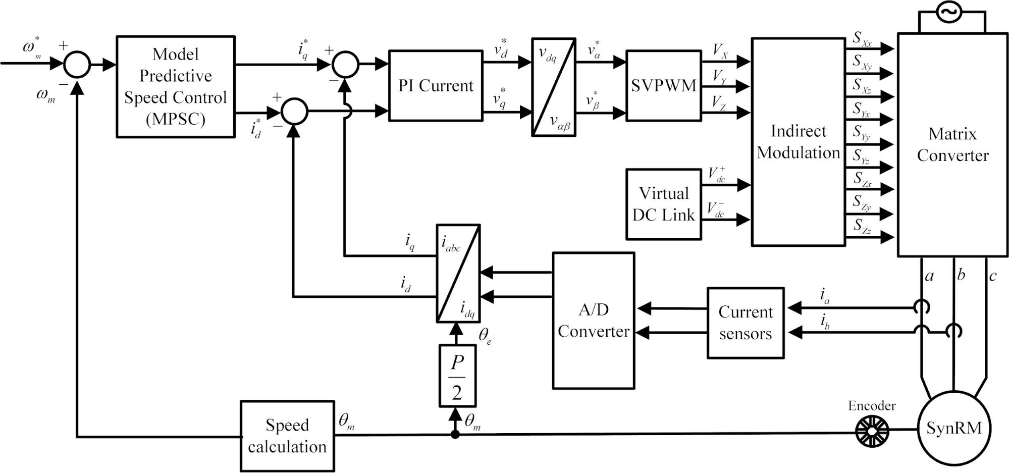
In this paper, the SynRM indirect matrix converter drive system uses model predictive speed controller (MPSC) and proportional-integral (PI) current controller based on the mechanical model of motor. A comprehensive block diagram of the overall drive system configuration is presented in Figure 1. The proposed speed drive system is based on an indirect matrix converter topology and incorporates several key components, including MPSC and PI current controllers, a modulation algorithm, the matrix converter unit, and a SynRM as the load. The detailed matrix converter and the controllers design are explained in the following subsection.
Figure 1. Block Diagram Systems
- Matrix Converter
The matrix converter is a novel type of AC-to-AC converter that performs direct power conversion in a single stage. Figure 2 presents the configuration of a 3×3 matrix converter. In this setup, each output line is connected to an inductive winding equipped with a back electromotive force (EMF) switch. The converter employs nine bidirectional power switches, enabling power flow in both directions. One of its key benefits is the elimination of a bulky DC-link capacitor. Additional advantages include the generation of sinusoidal waveforms at both input and output, as well as the ability to maintain a unity power factor. Despite its merits, the matrix converter has several limitations. Importantly, the voltage transfer ratio cannot exceed 86% of the input voltage. Moreover, it requires 18 fully controllable switching devices, and its control algorithms are notably complex. According to equation (1), the output and input voltages relationship are derived as
| 
| (1) |
where  ,
, and
and  are the output voltages of matrix converter . Then,
  ,
,  and
and  are the input voltages of matrix converter. This paper utilizes an indirect modulation approach for the matrix converter, implementing a virtual DC-link modulation algorithm. The modulation strategy is organized as a two-stage process, consisting of a virtual rectifier and inverter stages, both of which are described in detail. Figure 3 illustrates the equivalent topology of the matrix converter based on the virtual DC-link concept. The relationship between the virtual DC-link voltages and the three-phase input voltages is expressed using a switching function, as follows:
| 
| (2) |
where  is the virtual dc-link voltage and
  are the switching states of virtual rectifier stage. The three-phase output voltage and the virtual dc voltage relationship are derived as
| 
| (3) |
where  are the switching states of the virtual inverter stage. By combining equation (2) and equation (3), the resulting expression can be derived as follows
| 
| (4) |
Equation (4) is the indirect switching pattern of matrix converter. During one voltage cycle, the virtual DC-link depicted in Figure 4 is divided into twelve distinct sectors. The highest voltage level is selected for each voltage source cycle, as it corresponds to the voltage level produced by a conventional diode-bridge rectifier.
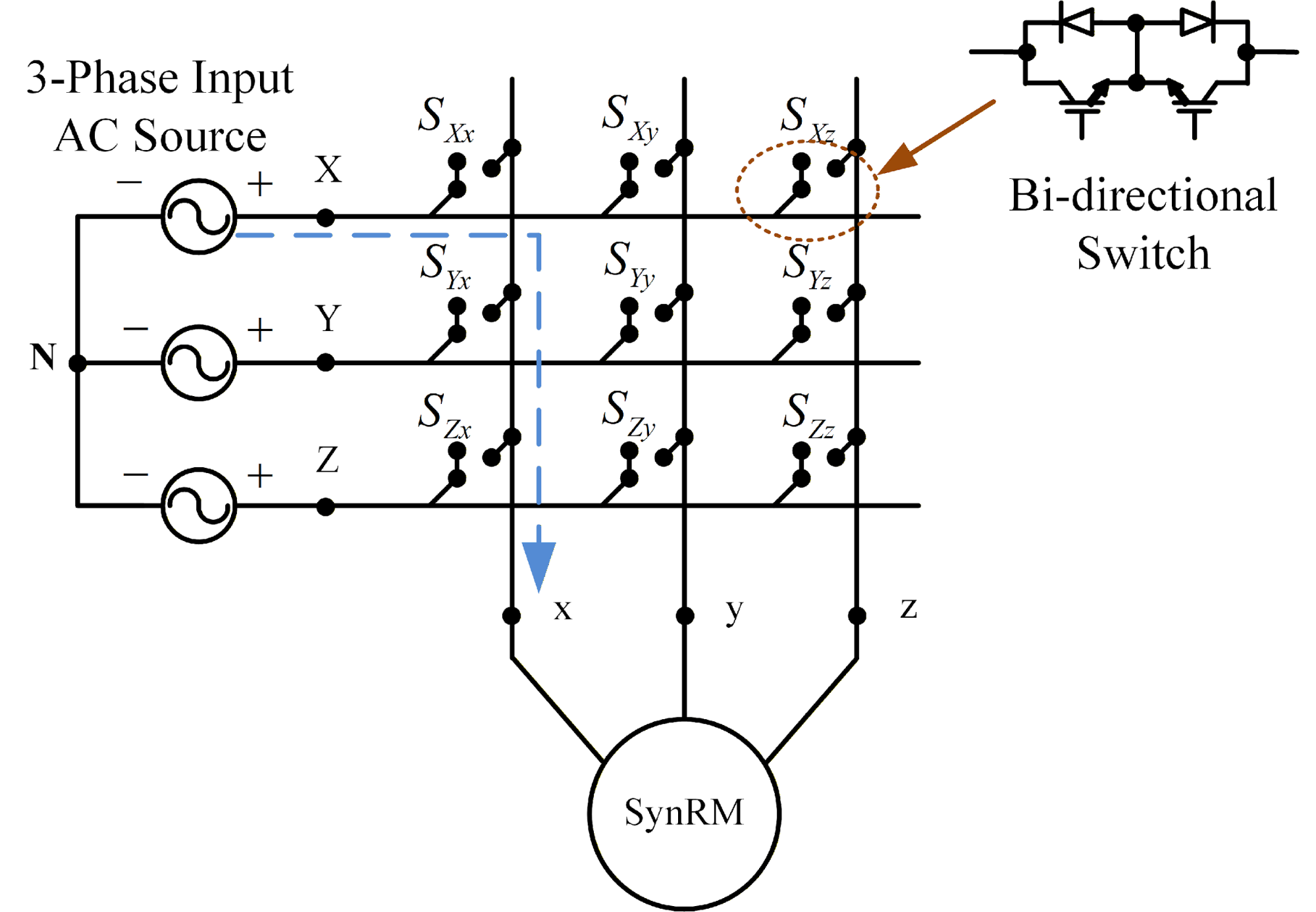
Figure 2. A 3x3 matrix converter configuration
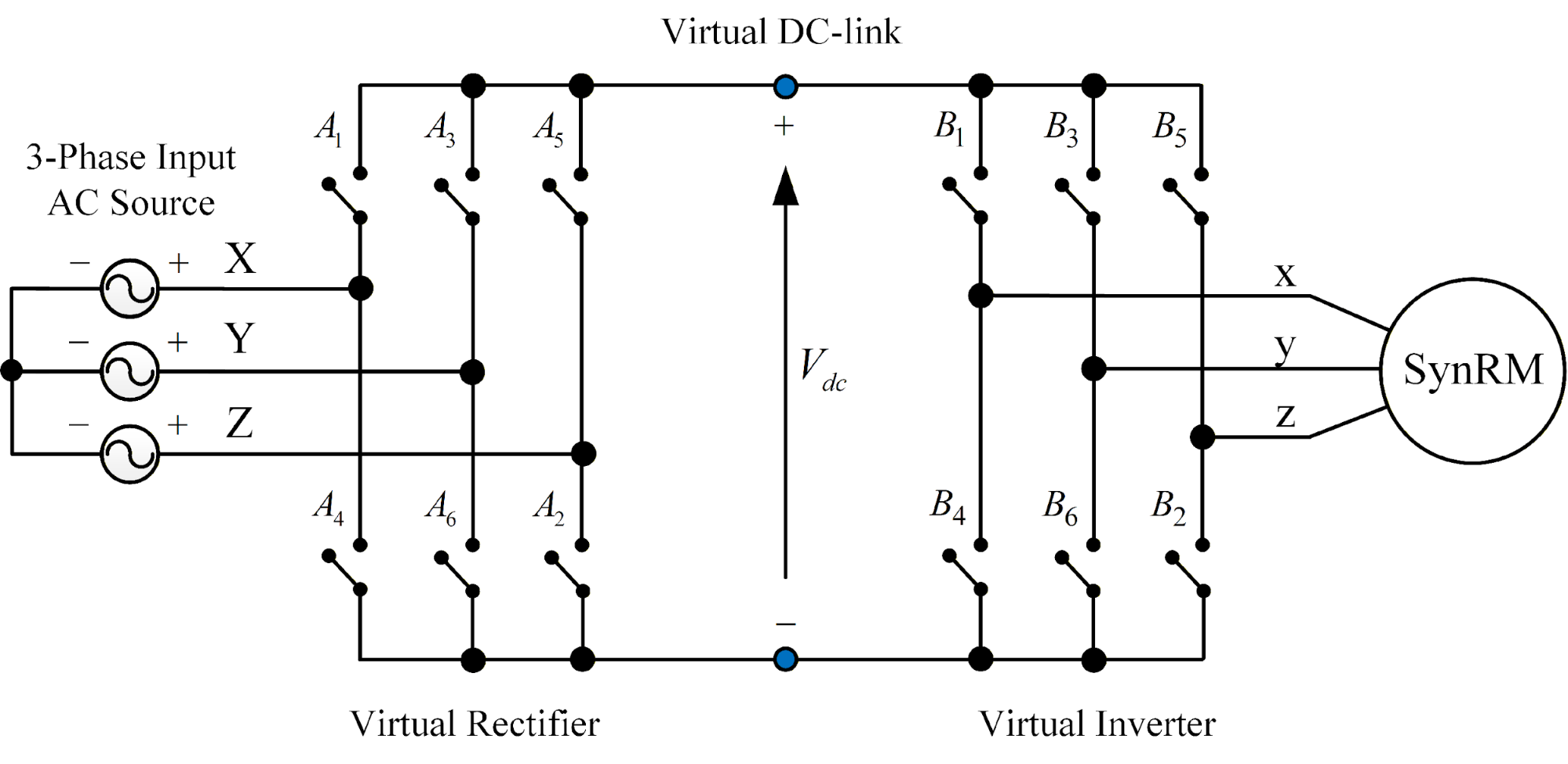
Figure 3. Virtual DC-link matrix converter
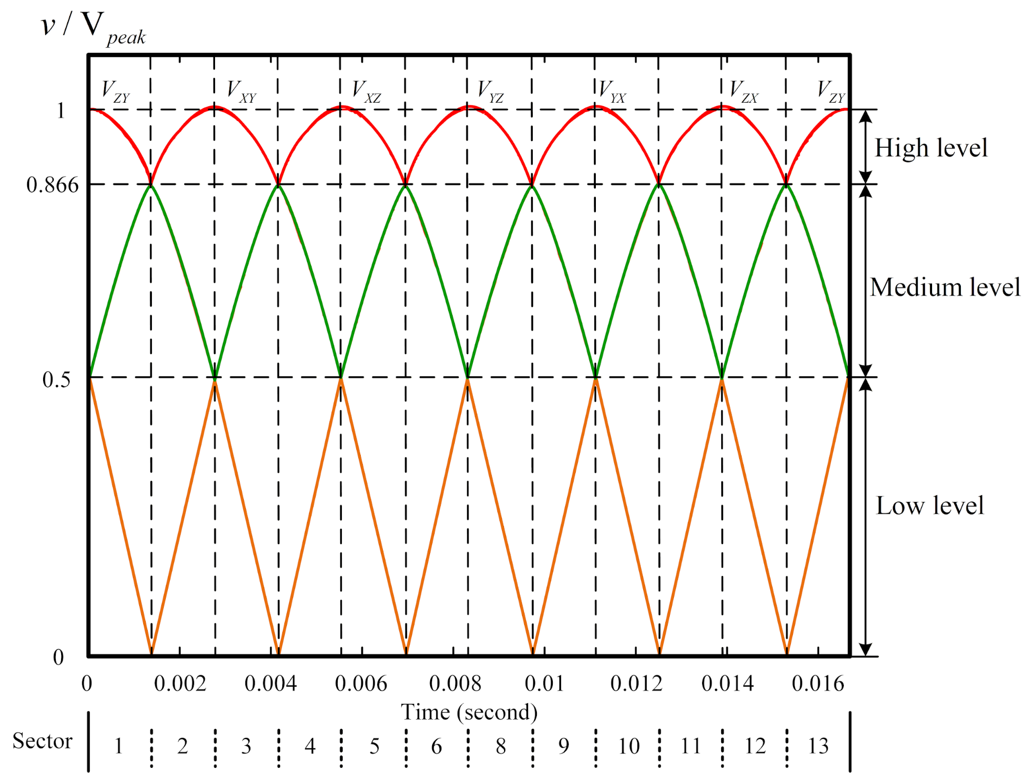
Figure 4. Three-level virtual DC-link voltages of matrix converter
- Model Predictive Speed Controller (MPSC)
The MPSC operates in discrete time, therefore, the uncontrolled plant must likewise be expressed in a discrete-time form. The discrete transfer function of the mechanical model of the SynRM can be written as [45].
| 
| (5) |
According to (5):
| 
| (6) |
| 
| (7) |
From inverse z-transform of equation (5), the predicted speed  is derived as
| 
| (8) |
where  and
and  are the inertia and friction coefficient of the motor,
  is the constant torque,
  is the sampling interval,
  is the measured speed and
  is the q-axis current. In this paper, even though the parameters change at every sampling step, the proposed controllers can still adapt smoothly because of the added augmented state variables and constraints. Based on (8), while considering the distinct operations on each side [46], the following can be expressed
| 
| (9) |
This paper also consider the speed error  , is derived as
| 
| (10) |
Then, the new augmented state variable is expressed as
| 
| (11) |
where the equation (11) is defined as
| 
| (12) |
A Laguerre function is also implemented in this system to avoid the high computational burden of a long control horizon for  . On other hand, to obtain optimal actuation the cost function formula is used here. The and cost function
  are shown as [46]
| 
| (13) |
| 
| (14) |
Then, the variables in equation (14) can be defined as
| 
| (15) |
| 
| (16) |
After that, by substituting equation (15) and equation (16) into equation (14), one can obtain as follows
| 

| (17) |
To make a simple equation (17), the  and
and  are obtain
To obtain a minimal , the partial derivative  is applied and the control input
  is obtain
| 
| (21) |
where is  is the state variable,
  the predictive control step,
  is the Laguerre coefficient, and
  is the Laguerre function vector,
  is the prediction horizon,
  is constant and
  also
also  and
and  are the weighting matrix,
  is the state feedback gain.
- Proportional-Integral (PI) Current Controller
The PI current controller implemented using pole-assignment technique. Then, it is essential establish an accurate mathematical model of the Synchronous Reluctance Motor (SynRM). This model serves as the foundation for analyzing the motor’s dynamic behavior and enables the systematic development and tuning of control strategies to ensure optimal performance under varying operational conditions. For simplification, the following assumptions are made: the motor is supplied with balanced three-phase voltages, magnetic saturation is neglected, the back electromotive force (EMF) is sinusoidal, core losses are ignored, and all motor parameters are considered constant. The voltage equations is derive as
| 
| (22) |
| 
| (23) |
from Equation (22) and equation (23), the transfer function in the s-domain is explained as
| 
| (24) |
| 
| (25) |
In the PI pole-assignment technique, the pole is chosen in the stable condition. The PI gain in the speed and current loops is derived as
| 
| (26) |
| 
| (27) |
The  is expressed as
| 
| (28) |
where  is the proportional gain,
  is the integral time constant,
  andare the damping coefficient and bandwidth also
  is the settling time. The damping coefficient chosen between
  that can be freely selected in order to achieve the desired performance. The is choosen based on the open-loop responses. From equation (28), the is easily obtained due to and are already selected. The PI pole-assignment technique is derived as
| 
| (29) |
In this paper the damping variable and time settling are selected as 1 in simulation. Also, due to make the system faster than the open-loop responses, the time settling selected become 0.2s when using the PI controller. Then, the d-q axis current control  and
and  . In this system the gain current loop
 and
and  . Also, in the q-axis
  and
and .
.
- RESULT AND DISCUSSION
The proposed control strategy was implemented and evaluated using the MATLAB Simulink environment in order to verify its performance and effectiveness under various operating conditions. Through simulation, the system's dynamic response, steady-state behavior, and robustness were thoroughly analyzed. Based on Figure 1, the control scheme employs an outer-loop predictive controller to regulate the motor speed by generating the reference torque-producing current,  , while the inner-loop PI controller ensures accurate tracking of the reference current. The modulation algorithm used for the matrix converter ensures proper switching sequences and voltage transfer ratio optimization, enabling efficient energy conversion. The electrical and mechanical parameters of the SynRM used in this study are summarized in Table 1. These parameters were carefully selected based on practical design considerations to ensure realistic simulation results. A fixed sampling interval of 100 μs was employed throughout the simulation to provide high control resolution and stability. Furthermore, the d-axis reference current,
  , was set to 2 A to enhance the motor's constant torque capability, ensuring improved performance in the low-speed to the high-speed region.
The simulation results of the proposed indirect matrix converter-based SynRM drive system are presented in the subsequent figures, providing a comprehensive performance of its dynamic and steady-state performance under various operating condition. Specifically, Figure 5 presents the transient response under a reference speed of 1000 r/min with an applied external load of 1  . The results clearly show the dynamic performance of the control structure during speed tracking. From the Figure 5, it is evident that the system exhibits a rapid rise time of approximately 0.043 second, indicating the controller’s capability to promptly respond to speed reference changes. The settling time is measured to be around 0.058 seconds, reflecting the system’s ability to quickly reach steady-state operation with minimal oscillations. The maximum overshoot is limited to only 0.47%, which highlights the effectiveness of the speed controller in avoiding excessive transient deviation from the desired reference. Additionally, the steady-state error is found to be 4.7 r/min, representing a small deviation from the target speed which is 0.47%, and is considered acceptable for high-performance industrial drive applications. The small error is existed because of a consequence of the predictive weighting selection and amount of prediction horizon in the MPSC.
Figure 6 illustrates the transient responses of the SynRM speed drive system during acceleration from a low-speed range to the rated speed using step change input. Specifically, from 200 r/min to 1800 r/min, covering a wide operational range representative of typical industrial requirements. As evident from the simulation results, the proposed drive system exhibits satisfactory dynamic performance across the entire adjustable speed range. The motor speed closely follows the reference trajectory with minimal overshoot and rapid acceleration. The settling time is directly proportional to the magnitude of the speed command. As the speed command increases, the settling time becomes longer. At a low speed of 200 r/min, the settling time is approximately 0.02 s, whereas at the rated speed of 1800 r/min, the settling time increases to 0.7 s. Therefore, the overall settling time ranges from 0.02s to 0.7s, which can still be classified as a fast-settling response within the considered operating range.
Figure 7 depicts the transient response of the proposed SynRM drive system under a reversed speed command scenario, where the reference speed is changed from 600 r/min to –600 r/min. This test performs the system’s ability to handle dynamic reversals in operating direction, which is critical for applications requiring frequent speed changes or regenerative braking. During the initial positive speed command of 600 r/min, the system exhibits a rise time of 0.023 seconds and a settling time of approximately 0.035 seconds, indicating a fast and well-damped response. When the reference speed is reversed to –600 r/min, the drive system maintains its performance, achieving a rise time of 0.060 seconds and a settling time of 0.069 seconds. Although the response to the negative command is slightly slower due to the inherent dynamics of direction reversal and the additional control effort required for deceleration and regeneration, the system remains stable and effectively tracks the new speed command without significant overshoot or oscillation. In addition, when reversed speed command, the SynRM must decelerate to zero before accelerating in the opposite direction, which introduces inertia-related delay. Then cost function in MPSC penalizes large control increments, preventing aggressive torque changes. This results in slightly longer settling time while maintaining stability. To further evaluate the tracking performance of the proposed drive system, a time-varying reference speed signal with a sinusoidal command at 600 r/min was applied in the
Figure 8. This test is designed to assess the system's ability to follow dynamic speed variations. As shown in the corresponding Figure 8, the speed response closely follows the sinusoidal reference trajectory throughout both the positive and negative half-cycles. The motor speed demonstrates smooth and continuous tracking with minimal phase lag, reflecting the effectiveness of the controller structure and modulation strategy in handling time-varying commands. The average speed tracking error over the entire test duration is calculated to be approximately 11.57 r/min, 2.261%, which indicates a high level of accuracy in speed regulation even under dynamic conditions. Overall, the simulation results using MATLAB obtained under various operating conditions including constant speed operation at 1000 r/min with external load, wide-range acceleration, reversed speed commands, and sinusoidal reference tracking. The proposed controllers demonstrate consistent dynamic stability, fast transient response, and minimal steady-state error. The controllers maintain low overshoot, short time settling, and accurate tracking performance across both low and high-speed regions. Furthermore, stable behavior during speed reversal and time-varying commands confirms the robustness of the predictive speed controller and the effectiveness of the cascaded PI current loop. Collectively, these findings validate that the proposed MPSC–PI control algorithm provides a reliable and high-performance solution for indirect matrix converter for SynRM drive systems, thereby supporting the main claim of this paper and leading directly to the concluding remarks.
Table 1. Parameters of SynRM
Parameters | Nominal Value |
Pole | 4 |
Rated Power | 560 W |
Rated Speed | 1800 r/min |
Rated Current | 3.4 A |
Stator Resistance | 2  |
d-axis inductance | 148 mH |
q-axis inductance | 67.2 mH |
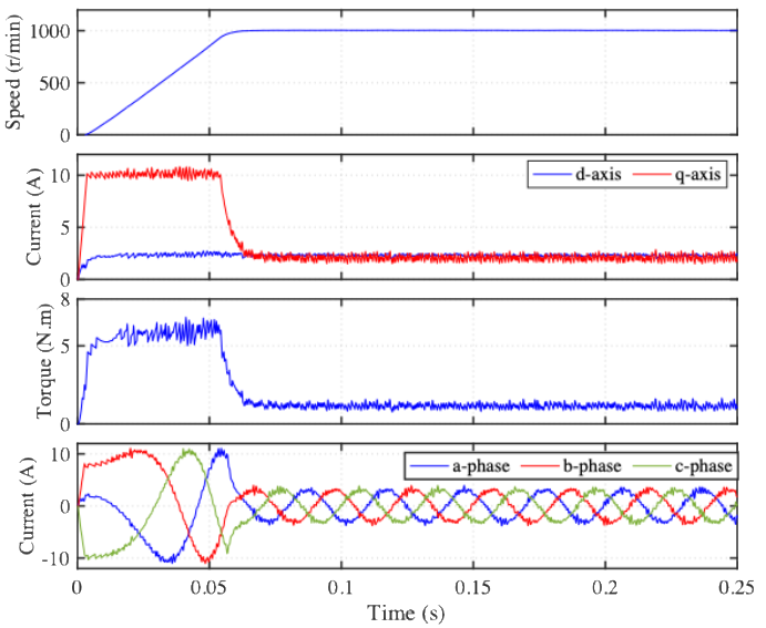
Figure 5. Transient response at 1000 r/min with 1 N.m external load
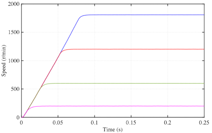
Figure 6. Transient response with different speed commands
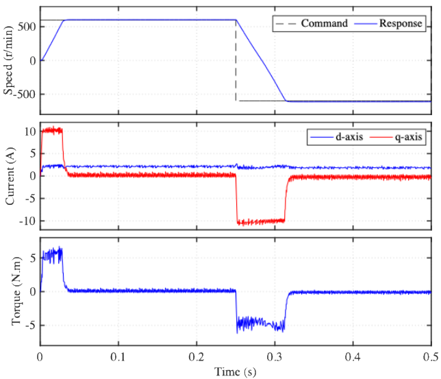
Figure 7. Reversed speed response at 600 r/min to -600 r/min
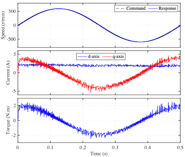
Figure 8. Tracking responses with sinusoidal speed command at 600 rpm
- CONCLUSIONS
This paper proposes speed and current controllers for SynRM by indirect modulation matrix converter. Specifically, the paper integrate model predictive speed controller (MPSC) in the outer loop and a Proportional-Integral (PI) current controller in the inner loop. The proposed drive systems successfully demonstrates that SynRM can be controlled, from low speed to the rated speed, using direct conversion AC-AC converter. The results show that the proposed drive system can handle the dynamic performance of the SynRM very well including fast settling time in transient responses less than 0.06s, stable performance across a broad speed range from 200 r/min to 1800 r/min and small average tracking error is approximately 11.57 r/min in the sinusoidal speed command. The merits of this control method make it possible to realize in industrial application due to its simple implementation characteristic including for elevator etc. On other hand, althought the real motor parameters is used in this paper, the experiment validation and verification is still needed for future reserach.
ACKNOWLEDGEMENT
The author would like to express his gratitude for the support provided by Faculty of Vocational Studies, Universitas Negeri Surabaya, through project number 537/UN38/HK/2025. Also, the authors declare no conflict of interest.
REFERENCES
- X. S. Li, et al., "Analysis and Simplification of Three-Dimensional Space Vector PWM for Three-Phase Four-Leg Inverters," IEEE Transactions on Industrial Electronics, vol. 58, pp. 450-464, 2011, https://doi.org/10.1109/TIE.2010.2046610.
- I. Abdulwahab, M. Ismaila, S. H. Sulaiman, I. Abdullahi Shehu, and M. Mohammed, “Simulation and Experimental Evaluation of a 5-Level Cascaded H-Bridge Inverter”, Vokasi Unesa Bull. Eng. Technol. Appl. Sci., vol. 2, no. 2, pp. 243–251, 2025, https://doi.org/10.26740/vubeta.v2i2.37172.
- A. M. Obais and A. A. Mukheef, “Design of a 120V, 5A SEPIC DC-DC Converter for Unipolar 120V DC Microgrid ”, Vokasi Unesa Bull. Eng. Technol. Appl. Sci., vol. 2, no. 3, pp. 655–665, 2025, https://doi.org/10.26740/vubeta.v2i3.44140.
- S. -S. Min and K. -M. Choo, "Cascaded Voltage-Control Method for a Diode-Front-End-Based Variable-Speed Synchronous Generator in a DC Power System," IEEE Access, vol. 13, pp. 186397-186407, 2025, https://doi.org/10.1109/ACCESS.2025.3626777.
- M. -S. Song, "Two-Series-Connected Two-Level PWM Inverter With Three-Level Input Feature: Offset Voltage Injection and Continuous/Discontinuous Modulation Strategies," IEEE Access, vol. 13, pp. 193997-194017, 2025, https://doi.org/10.1109/ACCESS.2025.3631859.
- L. K. Pittala, A. Chub, G. I. Orfanoudakis, A. Kuperman, M. Ricco and R. Mandrioli, "Active Power Sharing Control in Asymmetrical Bidirectional DC/DC Converter," IEEE Open Journal of Power Electronics, vol. 6, pp. 1980-1990, 2025, https://doi.org/10.1109/OJPEL.2025.3630546.
- S. Pirehbabi, R. Gavagsaz-Ghoachani, M. Phattanasak and S. Pierfederici, "Modular Converter Modeling With Cascaded Controllers for Enhanced Renewable Energy Integration," IEEE Access, vol. 13, pp. 191114-191125, 2025, https://doi.org/10.1109/ACCESS.2025.3630064.
- R. Arulmozhiyal and K. Baskaran, "Implementation of a Fuzzy PI Controller for Speed Control of Induction Motors Using FPGA," Journal of Power Electronics, vol. 10, pp. 65-71, 2010, https://doi.org/10.6113/JPE.2010.10.1.065.
- M. Utvić, P. Bontemps and D. Dujić, "Direct Arm Energy Control of the Modular Multilevel Matrix Converter," IEEE Access, vol. 11, pp. 1793-1805, 2023, https://doi.org/10.1109/ACCESS.2023.3234013.
- R. H. Cuzmar, A. Mora, J. Pereda, R. P. Aguilera, P. Poblete and S. Neira, "Computationally Efficient MPC for Modular Multilevel Matrix Converters Operating With Fixed Switching Frequency," IEEE Open Journal of the Industrial Electronics Society, vol. 4, pp. 748-761, 2023, https://doi.org/10.1109/OJIES.2023.3347101.
- M. A. Waghmare, B. S. Umre, M. V. Aware, A. Iqbal and A. Kumar, "Dual Stage Single-Phase to Multiphase Matrix Converter for Variable Frequency Applications," IEEE Transactions on Power Electronics, vol. 38, no. 2, pp. 1372-1377, 2023, https://doi.org/10.1109/TPEL.2022.3207515.
- A. W. S. Ramalho, M. A. Vitorino, M. B. d. R. Corrêa, L. A. L. d. A. C. Costa and E. R. Braga-Filho, "New Family of Two-to-Three-Phase AC–AC Indirect Matrix Converters With Open-End Rectifier Stage," IEEE Transactions on Industry Applications, vol. 58, no. 1, pp. 517-530, 2022, https://doi.org/10.1109/TIA.2021.3128369.
M. A. Waghmare, B. S. Umre, M. V. Aware, A. Iqbal and A. Kumar, "Dual Stage Single-Phase to Multiphase Matrix Converter for Variable Frequency Applications," IEEE Transactions on Power Electronics, vol. 38, no. 2, pp. 1372-1377, 2023, https://doi.org/10.1109/TPEL.2022.3207515.
- H. Dan, P. Zeng, W. Xiong, M. Wen, M. Su and M. Rivera, "Model predictive control-based direct torque control for matrix converter-fed induction motor with reduced torque ripple," CES Transactions on Electrical Machines and Systems, vol. 5, no. 2, pp. 90-99, 2021, https://doi.org/10.30941/CESTEMS.2021.00012.
- T. B. D. Santos, I. Oliani, R. Figueiredo, D. Albieiro, A. Pelizari and A. J. Sguarezi Filho, "Robust Finite Control Set Model Predictive Current Control for Induction Motor Using Deadbeat Approach in Stationary Frame," IEEE Access, vol. 11, pp. 13067-13078, 2023, https://doi.org/10.1109/ACCESS.2022.3223385.
- Z. Zhou, J. Wang and S. Zhang, "Speed Synchronization Control Strategy of Dual-Motor System With Explicit Model Predictive Control," IEEE Journal of Emerging and Selected Topics in Power Electronics, vol. 12, no. 3, pp. 2787-2798, 2024, https://doi.org/10.1109/JESTPE.2024.3390999.
- S. H. Kim and K. -K. K. Kim, "Model Predictive Control for Energy-Efficient Yaw-Stabilizing Torque Vectoring in Electric Vehicles With Four In-Wheel Motors," IEEE Access, vol. 11, pp. 37665-37680, 2023, https://doi.org/10.1109/ACCESS.2023.3266330.
- C. Yu et al., "Research on Dynamic and Steady-State Characteristics of Grid-Following/Grid-Forming Hybrid Control Based on Model Predictive Control," IEEE Open Journal of Power Electronics, vol. 6, pp. 909-918, 2025, https://doi.org/10.1109/OJPEL.2025.3569981.
- D. Zhou, J. Wang, Y. Li, J. Zou and K. Sun, "Model Predictive Power Control of Grid-Connected Quasi Single-Stage Converters for High-Efficiency Low-Voltage ESS Integration," IEEE Transactions on Industrial Electronics, vol. 69, no. 2, pp. 1124-1134, 2022, https://doi.org/10.1109/TIE.2021.3059539.
- M. Liu, Y. Shi and H. Gao, "Aggregation and Charging Control of PHEVs in Smart Grid: A Cyber–Physical Perspective," Proceedings of the IEEE, vol. 104, no. 5, pp. 1071-1085, 2016, https://doi.org/10.1109/JPROC.2015.2512500.
- M. I. Grairia et al., "Modified Model-Free Predictive Control for Reliable Operation of Multiple Parallel Grid-Forming Inverters," IEEE Access, vol. 13, pp. 122862-122875, 2025, https://doi.org/10.1109/ACCESS.2025.3588042.
- C. R. Baier, F. A. Villarroel, M. A. Torres, M. A. Pérez, J. C. Hernández and E. E. Espinosa, "A Predictive Control Scheme for a Single-Phase Grid-Supporting Quasi-Z-Source Inverter and its Integration With a Frequency Support Strategy," IEEE Access, vol. 11, pp. 5337-5351, 2023, https://doi.org/10.1109/ACCESS.2023.3236499.
- Y. Xu, Z. Wang, P. Liu, Q. Wei, F. Deng and Z. Zou, "The Modular Current-Fed High-Frequency Isolated Matrix Converters for Wind Energy Conversion," IEEE Transactions on Power Electronics, vol. 37, no. 4, pp. 4779-4791, 2022, https://doi.org/10.1109/TPEL.2021.3123204.
- Y. Li, Q. Wu, Y. Jiang, J. Chen and Q. Zhou, "Coordinated Inertial Response Control Strategy for Modular Multilevel Matrix Converter and Low Frequency Offshore Wind Farm," IEEE Transactions on Industry Applications, vol. 61, no. 5, pp. 7967-7976, 2025, https://doi.org/10.1109/TIA.2025.3556796.
- Z. Dong, Z. Li, L. Du, Y. Liu and Z. Ding, "Coordination Strategy of Large-Scale DFIG-Based Wind Farm for Voltage Support With High Converter Capacity Utilization," IEEE Transactions on Sustainable Energy, vol. 12, no. 2, pp. 1416-1425, 2021, https://doi.org/10.1109/TSTE.2020.3047273.
- M. Zou, Y. Wang, C. Zhao, J. Xu, X. Guo and X. Sun, "Integrated Equivalent Model of Permanent Magnet Synchronous Generator Based Wind Turbine for Large-scale Offshore Wind Farm Simulation," Journal of Modern Power Systems and Clean Energy, vol. 11, no. 5, pp. 1415-1426, 2023, https://doi.org10.35833/MPCE.2022.000495.
- A. W. S. Ramalho, M. A. Vitorino, M. B. d. R. Corrêa, L. A. L. d. A. C. Costa and E. R. Braga-Filho, "New Family of Two-to-Three-Phase AC–AC Indirect Matrix Converters With Open-End Rectifier Stage," IEEE Transactions on Industry Applications, vol. 58, no. 1, pp. 517-530, 2022, https://doi.org/10.1109/TIA.2021.3128369.
- Y. Li, Y. W. Li and Z. Quan, "Systematic Synthesis and Derivation of Multilevel Converters Using Common Topological Structures With Unified Matrix Models,” IEEE Transactions on Power Electronics, vol. 35, no. 6, pp. 5639-5659, 2020, https://doi.org/10.1109/TPEL.2019.2948580.
- E. L. Carvalho, A. Blinov, P. Emiliani, A. Chub and D. Vinnikov, "Three-Phase Bidirectional Isolated AC–DC Matrix-Converter With Full Soft-Switching Range," IEEE Access, vol. 11, pp. 119270-119283, 2023, https://doi.org/10.1109/ACCESS.2023.3327224.
- Y. Li, H. Tian and Y. R. Li, "Matrix-Based Approach for Open-Circuit Fault-Tolerant Analysis and PWM Design of Active Neutral-Point-Clamped Converters," IEEE Transactions on Power Electronics, vol. 37, no. 12, pp. 14706-14719, 2022, https://doi.org/10.1109/TPEL.2022.3193972.
- H. Dan, W. Yue, W. Xiong, Y. Liu, M. Su and Y. Sun, "Open-Switch and Current Sensor Fault Diagnosis Strategy for Matrix Converter-Based PMSM Drive System," IEEE Transactions on Transportation Electrification, vol. 8, no. 1, pp. 875-885, 2022, https://doi.org/10.1109/TTE.2021.3109093.
- W. Deng, "Maximum Voltage Transfer Ratio of Matrix Converter Under DTC With Rotating Vectors," IEEE Transactions on Power Electronics, vol. 36, no. 6, pp. 6137-6141, 2021, https://doi.org/10.1109/TPEL.2020.3033414.
- J. Jongudomkarn, J. Liu, Y. Yanagisawa, H. Bevrani and T. Ise, "Model Predictive Control for Indirect Boost Matrix Converter Based on Virtual Synchronous Generator,” IEEE Access, vol. 8, pp. 60364-60381, 2020, https://doi.org/10.1109/ACCESS.2020.2983115.
- X. Wang et al., "Well-Conditioned Identifiability Criteria With Observability Degree for Parameter Estimation of Permanent Magnet Synchronous Motors," IEEE Transactions on Transportation Electrification, vol. 11, no. 3, pp. 7195-7206, 2025, https://doi.org/10.1109/TTE.2024.3524783.
- K. B. Tawfiq, M. N. Ibrahim and P. Sergeant, "An Enhanced Fault-Tolerant Control of a Five-Phase Synchronous Reluctance Motor Fed From a Three-to-Five-Phase Matrix Converter," IEEE Journal of Emerging and Selected Topics in Power Electronics, vol. 10, no. 4, pp. 4182-4194, 2022, https://doi.org/10.1109/JESTPE.2022.3148188.
- R. Cardenas, R. Pena, J. Clare and P. Wheeler, "Control of the Reactive Power Supplied by a Matrix Converter," IEEE Transactions on Energy Conversion, vol. 24, no. 1, pp. 301-303, 2009, https://doi.org/10.1109/TEC.2008.2003213.
- H. Dan, W. Yue, W. Xiong, Y. Liu, M. Su and Y. Sun, "Open-Switch and Current Sensor Fault Diagnosis Strategy for Matrix Converter-Based PMSM Drive System," IEEE Transactions on Transportation Electrification, vol. 8, no. 1, pp. 875-885, 2022, https://doi.org/10.1109/TTE.2021.3109093.
- Q. Chang, B. Zhou, C. Lu, S. Jiang and J. Wei, "A Sinusoidal Doubly Salient Electromagnetic Machine Drive Fed by Third-Harmonic Injection Two-Stage Matrix Converter With Integrated Injection Inductor," IEEE Transactions on Industrial Electronics, vol. 71, no. 4, pp. 3418-3428, 2024, https://doi.org/10.1109/TIE.2023.3274856.
- Y. Zhao, L. Ren, Z. Liao, and G. Lin, “A Novel Model Predictive Direct Torque Control Method for Improving Steady-State Performance of the Synchronous Reluctance Motor,” Energies, vol. 14, no. 8, p. 2256, 2021, https://doi.org/10.3390/en14082256.
- Q. Chang, B. Zhou, C. Lu, S. Jiang and J. Wei, "A Sinusoidal Doubly Salient Electromagnetic Machine Drive Fed by Third-Harmonic Injection Two-Stage Matrix Converter With Integrated Injection Inductor," IEEE Transactions on Industrial Electronics, vol. 71, no. 4, pp. 3418-3428, 2024, https://doi.org/10.1109/TIE.2023.3274856.
- L. Ntogramatzidis, S. Cuoghi, M. Ricco, R. Mandrioli and G. Grandi, "A Novel MIMO Control for Interleaved Buck Converters in EV DC Fast Charging Applications," IEEE Transactions on Control Systems Technology, vol. 31, no. 4, pp. 1892-1900, 2023, https://doi.org/10.1109/TCST.2023.3237497.
- M. Fikrul Ma’arif, “Design Lighting System Based on PID Control and Node-RED”, Vokasi Unesa Bull. Eng. Technol. Appl. Sci., vol. 1, no. 3, pp. 1–8, 2024, https://doi.org/10.26740/vubeta.v1i3.35454.
- A. Sabo, “PID controller tuning for an AVR system using Particle Swarm Optimisation Techniques and Genetic Algorithm Techniques; A comparison based approach ”, Vokasi Unesa Bull. Eng. Technol. Appl. Sci., vol. 2, no. 2, pp. 270–280, 2025, https://doi.org/10.26740/vubeta.v2i2.36821.
- S. Masoudi and H. Mehrjerdi, "A Multilayer Perception Trained Method in Speed Control of a Linear Switched Reluctance Motor," IEEE Transactions on Power Electronics, vol. 37, no. 4, pp. 4475-4483, 2022, https://doi.org/10.1109/TPEL.2021.3125606.
- K.-K. Shyu and C.-K. Lai, “Incremental motion control of synchronous reluctance motor via multisegment sliding mode control method,” IEEE Trans. Control Syst. Technol., vol. 10, no. 2, pp. 169–176, 2002, https://doi.org/10.1109/87.987062.
- L. Wang, Model Predictive Control System Design and Implementation Using MATLAB®. in Advances in Industrial Control. London: Springer London, 2009, https://doi.org/10.1007/978-1-84882-331-0.
- K. Cao, X. Liu, M. He, X. Meng, and Q. Zhou, “Active-clamp resonant power factor correction converter with output ripple suppression,” IEEE Access, vol. 9, pp. 5260–5272, 2021, https://doi.org/10.1109/ACCESS.2020.3048012.
Nur Vidia Laksmi B. (Indirect Matrix Converter Based Synchronous Reluctance Motor Drive Systems using Model Predictive Control)