ISSN: 2685-9572 Buletin Ilmiah Sarjana Teknik Elektro
Vol. 8, No. 1, February 2026, pp. 165-191
Adaptive Protection Scheme Using Optimal Coordination of Directional Overcurrent Relays for Active Distribution Networks
Omar Muhammed Neda
Sunni Diwan Endowment, Iraq
ARTICLE INFORMATION |
| ABSTRACT |
Article History: Received 13 October 2025 Revised 17 January 2026 Accepted 03 February 2026 |
| 
Directional overcurrent relays (DOCRs) are widely used for the protection of distribution and sub-transmission systems due to their simplicity and cost-effectiveness. Proper coordination of these relays is essential to ensure selectivity, reliability, and fast fault clearance. However, due to the complex and nonlinear nature of modern power systems with high-level constraints, achieving optimal coordination is challenging. Traditional protection schemes relying on fixed relay settings often fail under dynamic operating conditions, leading to increased relay operating times, coordination violations, and protection blind zones. This paper develops an optimization-based DOCR coordination framework to minimize total inverse relay operating time while preserving coordination constraints, including predefined Coordination Time Intervals (CTIs) between primary and backup relays. Two strategies are proposed: a combined method, applying a single relay setting group for all network configurations, and an adaptive method, generating specific relay setting groups for each configuration or cluster. The adaptive method also incorporates relay characteristic curve tuning, allowing each DOCR to select the most suitable inverse-time characteristic. Both strategies are implemented using a Genetic Algorithm (GA) and tested on IEEE 8-bus system. Simulation results show that the adaptive method significantly outperforms the combined strategy. In the IEEE 8-bus system, total operating time is reduced from 56.7742 s to 13.0026 s (≈81.7%). However, its practical deployment may require reliable communication and configuration detection. These results confirm that the GA-based adaptive DOCR strategy provides faster, more selective, and reliable protection, making it highly suitable for modern active distribution networks. |
Keywords: Adaptive Protection; Directional Overcurrent Relays; Relay Coordination; Distribution Network; Optimal Settings |
Corresponding Author: Omar Muhammed Neda, Sunni Diwan Endowment, Iraq. Email: omar.neda88@gmail.com |
This work is open access under a Creative Commons Attribution-Share Alike 4.0 
|
Document Citation: O. M. Neda, “Adaptive Protection Scheme Using Optimal Coordination of Directional Overcurrent Relays for Active Distribution Networks,” Buletin Ilmiah Sarjana Teknik Elektro, vol. 8, no. 1, pp. 165-191, 2026, DOI: 10.12928/biste.v8i1.14954. |
- INTRODUCTION
Because many modern electrical networks have become much more complex than what has previously existed, it is true that these networks are becoming increasingly dependent upon them having comprehensive protection systems in order to keep them functioning correctly without interruption. The function of protective relay systems is to provide protection to electrical networks by locating and removing any faults that occur, which allows equipment to avoid damage, allows electricity users to experience fewer interruptions in their power usage (socket time), and avoid catastrophic events. As electricity usage continues to grow rapidly, the development of new types of power systems and the increasing integration of renewable energy sources and technologies such as photovoltaics have created an entirely new level of complexity in operating power systems, which has led to protection being one of the more serious issues facing the operation of the power industry [1].
Coordination of fast and selective protection is necessary. Fast coordination places less stress on equipment than slower forms of coordination and will minimize the amount of damage that occurs during faults. Selective coordination prevents unnecessary outages from occurring in those areas that are unaffected by a fault. Directional overcurrent relays (DOCRs) are typically utilized for primary protection on each distribution feeder and provide secondary or backup protection for meshed or interconnected electrical systems. Coordination of DOCRs can be difficult due to the continually changing nature of the electrical system with the increase of Distributed Generation (DG). DG creates large fluctuations in both magnitude and direction of the fault current [2]. Over the past decades, numerous methods have been proposed to optimize relay coordination using mathematical, heuristic, and evolutionary algorithms, yet further innovation is needed to address modern active distribution network complexities [3].
- Conceptual Foundations and Motivational Frameworks
Modern power systems continue to face significant challenges in developing and operating protective coordination, which protects against equipment damage from failure or an interruption and provides for the safe operation of the grid's equipment. Protecting distribution systems warrants using both directional overcurrent devices (DOCRs) and distance relays as essential elements of a protective coordination strategy because these types of devices are widely used for the coordination of fault protection and equipment distribution systems. Doctrines (overcurrent) detect fault conditions based on the current flowing in each direction along with the site's voltage phasor (by using potential transformers) and then provide information about where the fault has occurred. Although the cost of a DOCR is usually higher than an ordinary overcurrent relay, the increased ability to discriminate between faults makes it necessary for effective protection when coordinating primary and secondary circuit protection devices [4].
Distance relay protection generally includes two zones of protection: Zone 1 protects an area that represents approximately 80% of the distance of the line to a fault with an instantaneous trip function. Zone 2 Zone - provides a backup for all of the protected line and about 20% of the shortest length of lines adjacent, but has a short time delay [5]. Coordinating DOCRs and distance relays is a constrained nonlinear optimization problem [6]. Proper time selectivity between backup and primary relays must be maintained to avoid simultaneous or missed operations, which could compromise system protection. The challenge intensifies in active distribution networks, particularly with increasing integration of DG and the transition toward smart grids [7][8].
DG units introduce bidirectional power flows and variable fault currents, which can increase or decrease unpredictably depending on DG location and output [9][10]. Typically, distance relay protection will have two zones of protection. Zone 1 provides an instantaneous trip for about 80% of the line distance to a fault. Zone 2 is a backup for the entire length of the protected line and about 20% of the shortest adjacent line but is delayed momentarily [11].
The development of adaptive protection processes has been a very successful approach with the ability to change relay settings based on the topology or operating condition of the power system. Through defining the relay setting groups based on the configuration or cluster, adaptive protection reduces complicity of co-coordinating multiple relays and improves fault discrimination; however, the majority of available schemes do not provide the capability to optimise both the relay characteristic curve(s) as well as the Pickup Current and Plug Setting Multiplier (PSM), which will slow response time of the relay and reduce the reliability of both schemes and relays.
The limitations and challenges present in this study lead to an approach based upon GA which brings together fast, dependable, and adaptive relay coordination that will take into consideration the current topology of a network and student relay settings as required by network conditions as well as provide a way to minimize the operating time and blind zones while also enabling a reliable and selective protective function provided to multiple scenarios.
- Literature Review
The coordination of distribution overcurrent relay (DOCRs) will be influenced by numerous dynamic factors (e.g., frequent/topological change) and a high level of penetration of distributed generation (DG) units on a modern distribution network [12]. Many different methodologies have been suggested in the literature to aid in the coordination of DOCRs for properly coordinated overcurrent protection in modern distribution networks [13]. These methods aim to optimize relay settings under a wide range of operating conditions, particularly in networks with high DG penetration.
Linear Programming (LP) has been suggested in [14] as a method to coordinate the timing of overcurrent relays due to its simplicity of formulation and computational efficiency; however, LP does not have good applicability to the complex, nonlinear constraints typically found in real-world power systems. As an alternative, the graphical sequential programming approach was suggested in [15]. This approach is intuitive and provides useful visual assistance for relay coordination; it is not easily scalable, and for extremely large or heavily meshed power systems, this approach becomes impractical.
Khatua and Mukherjee [16] proposed an adaptive overcurrent protection scheme for station blackout events in NPPs utilizing integrated microgrids. They emphasized the importance of adaptive relay settings in dynamic and sensitive settings. Similarly, ElSayed and Elattar [17] combined HHO with SQP to enhance the coordination of DOCRs. The algorithm directly considers the impact of DG on relays, leading to improved relay performance and enhanced protection selectivity. Fatemi and Samet [18] included the DG voltage parameters in the coordination process of DOCRs, limiting the energy shortfall caused by DG, and demonstrating the impact of DG on relay protection schemes in real-life applications.
Metaheuristic optimization techniques show promise in improving the coordination of Directional Overcurrent Relay (DOCR). Mishra et al. [19] introduced a method of positive sequence relay protection for solar-integrated distribution systems, which enhanced the reliability of fault detection in renewable-dominated systems. Akdag and Yeroglu [20] used the Manta Ray Foraging Optimization (MRFO) algorithm for optimizing relay settings in meshed distribution networks and emphasized the ability to adapt to different configurations of the distribution network. Saleh and Mehrizi-Sani [21] introduced the use of harmonic directional overcurrent relays for protection against the potential challenges associated with non-synchronous renewable generation (DG) sources in inverter-based islanded microgrids.
Moreover, the Sine Cosine Algorithm (SCA) was implemented in Sarwagya et al. [22] to solve the issue of optimal coordination of directional overcurrent relays (DOCRs) within the context of complicated network topologies, thereby demonstrating the resilience of metaheuristics under different operational constraints. Ghotbi-Maleki et al. [23] have created a method of overcurrent protection based on setting groups for Active Distribution Networks (ADN) using Mixed Integer Linear Programming (MILP) which provides greater flexibility of coordination under dynamic operating conditions. Regarding this subject, Jazayeri et al. [24] proposed a framework utilizing a multi-agent system (MAS) to protect against the problems presented within DG integrated networks through a hierarchical and decentralized approach. Finally, Elmitwally et al. [25] researched the utilization of optimal fault current limiters (FCL) and optimized overcurrent relay settings as a means of reducing the effects of DG on networks with changing topologies.
According to Amraee et al. [26] , multi-step under-frequency relay systems were created specifically for standalone locations with an added level of adaptability that is not available with traditional overcurrent protective relay systems, extending that concept to under-frequency protective relays, as well. Nascimento and others [27] proposed adaptive overcurrent techniques to be used in distribution systems that would automatically alter relay settings due to topological changes and load fluctuations. Abdelhamid et al. [28] used a modified school-based optimization (MSBO) to allow multiple teacher relationships throughout the learning process. His proposed MSBO enhances the ability to share knowledge and to better utilise the strength of the created population to coordinate relays in the changing environment where they operate.
Article [29] proposed a Tunicate Swarm Algorithm (TSA) to coordinate distance relays and DOCRs and tested the TSA in an 8-bus protection system. The TSA was based on the principles of crowd navigation and foraging behavior of tunicates. The TSA was compared with other metaheuristic approaches and was shown to provide a means of improving coordination in protection systems. Article [30] presented a Hardware-In-the-Loop (HIL) testing method to evaluate the performance of protective relays in a real-time digital simulation environment. The HIL testing utilized two SEL-351 relays in a combined HIL simulation to show the validity of relay coordination both before and after fault events and provided an accurate form of verification for the proposed settings using real-life relay event history. Article [31] developed an Adaptive Fuzzy Directional Bat Algorithm (AFDBA) to provide optimal settings for DOCR in microgrid systems. By utilizing a Fuzzy Inference System (FIS) within the Bat Algorithm to generate optimal settings, the AFDBA provided an adaptive and accurate way to verify relay coordination in an adaptive fashion to changing system conditions.
According [32] an innovative way to coordinate protection was developed by using FCLs to mitigate miscoordination caused by SG integration's higher fault current levels. JSO was applied to find the optimum number of FCLs, their corresponding sizes and locations, with the goal of minimizing the installation cost of the equipment and the operating time for DOCRs. Additionally, this framework also looked at how best to place DGs optimally, providing the opportunity for an integrated and economical solution to protection. Similarly, in [33], a protection coordination strategy was developed for radial distribution systems containing IBDERs. The response time, sensitivity, and selectivity of DOCRs with respect to IBDERs were assessed, and a multi-objective coordination framework was created to produce a coordinated set of relay settings. Finally, the verification of this method was done via simulation, which demonstrated a marked improvement in protective performance for a range of IBDER scenarios.
A dynamic coordination scheme is proposed for distribution systems (including distributed generation (DG)), which are used for distributed generation (DG). This scheme allows for changes to the settings of digital overcurrent relays (DOCRs) to occur automatically in response to operating conditions and other changes to the systems, such as DG output changes, and the use of Chicken Swarming Optimization (CSO) to improve the coordination and reliability of DOCRs. The proposed method was validated on two systems: the 9-bus Canadian system and the IEEE 30-bus network [34] An alternative optimal coordination technique uses fractional-order derivatives to define the war optimization process. This technique minimizes the total time spent by relays operating at different locations. The Fractional-Order Derivative War Optimizer (FODWO) was developed by Al-Bhadely et al. [35] to support various load levels and DG output uncertainty using a fuzzy monte Carlo simulation scheme that takes into account the multiple relay settings. The results demonstrate that by utilizing the dual-setting feature, it is possible to provide good coordination robustness across a variety of operating scenarios while maintaining relay selectivity [36].
Other advanced optimization strategies, including Improved Firefly Algorithm (IFA) [37], Grey Wolf Optimizer (GWO) [38], Teaching–Learning-Based Optimization (TLBO) [39], Biology-Based Optimization (BBO), enhanced Elite Marine Predator Algorithm (EMPA) [40], Differential Evolution method (DE) [41], Non-Dominated Sorting GA-II (NSGA-II) [42], Modified Backtracking Search (MBS) technique [43], improved firefly algorithm [44], Enhanced White Shark Optimizer (EWSO) [45], Modified Electromagnetic Field Optimization Algorithm (MEFO) [46], Improved Seagull Optimization Algorithm (ISOA) [47], Enhanced Grey Wolf Optimizer (EGWO) [48], Imperialistic Competition Algorithm (ICA) [49] and Modified Evaporation Rate Water Cycle Algorithm (MERWCA) [50], which confirmed superior performance in DOCR coordination compared to conventional techniques.
In addition, a modified teaching-based optimization technique was used in [51], and an analytical approach was investigated in [52] to solve the DOCR problem. Enhanced group search algorithms were employed in [53], and an alternative firefly algorithm was applied in [54] for different IEEE test systems. In [55], protection coordination was addressed under both grid-connected and islanded operating modes. Wadood et al. presented a modified swarm-based optimization method for DOCR coordination. Their findings indicated that the modified algorithm improves convergence performance and protection selectivity over baseline swarm intelligence approaches [56]. Also, different optimization approaches were projected for solving the DOCR coordination problem, including Hybrid Water Cycle Moth-Flame Optimization (HWCMFO) [57] and hybrid Genetic–Linear Programming (GA–LP) [58]. In [59], the Multiverse Optimization (MVO) algorithm was applied for optimal DOCR coordination, demonstrating superior performance compared to the other techniques.
Although there are many ways to do this type of work, there are still many holes in what has been developed; Very few methods on the market today are set up to optimize each of the following three items; Pickup Current, PSM and Relay Characteristic Curve for each Network Configuration. Current approaches lack adaptability to real-time conditions, and many have not taken into account the Protection Blind Zone. These limitations led to the development of a proposed GA-based Combined and Adaptive DOCR strategy. The objectives of this strategy are to increase the effectiveness of coordinating efforts, reduce operating times, and improve reliability in an evolving Distribution Network environment (see Section 1.3 for additional detail).
Table 1 summarizes recent protection coordination methods for active distribution networks, comparing their handling of DG integration, adaptability, optimization techniques, and test systems. Unlike many existing works, the proposed combined and adaptive strategies use GA to provide both universal and configuration-specific relay settings, resulting in improved flexibility and faster relay operation under varying conditions.
Table 1. Comparison of protection coordination approaches in distribution networks
Ref. | Protection Approach | Consideration of DG effect | Adaptability to Config Changes | Optimization Algorithm | Relay Setting Strategy | Test Systems |
[9] | Conventional coordination using LP | ❌ | ❌ | LP | Fixed | IEEE 6 bus |
[10] | Graphical sequential coordination | ❌ | ❌ | Sequential Quadratic Programming | Fixed | IEEE-6 and 30 bus |
[12] | Hybrid HHO + SQP for DG systems | ✅ | ❌ | HHO + SQP | Fixed | IEEE-6 and 30 bus |
[13] | Voltage-sensitive DOCR coordination | ✅ | ❌ | GA | Fixed | IEEE 33 bus |
[14] | Positive sequence-based protection | ✅ | ❌ | None specified | Fixed | CIGRE 14-bus distribution system |
[15] | Metaheuristic relay coordination | ✅ | ✅ | MRFO | Fixed | 9, 15 and 10 bus |
[16] | Harmonic-based DOCR scheme | ✅ | ✅ | None specified | Harmonic-based | Islanded microgrid |
[17] | Metaheuristic using SCA | ✅ | ✅ | SCA | Fixed | 3, 8, 15 and 30 test systems |
[18] | Group-setting via MILP | ✅ | ✅ | MILP | Multi-setting groups | 19-bus and IEEE 33-bus networks |
[19] | Multi-agent decentralized system | ✅ | ✅ | None specified | Decentralized | DG-integrated network |
[20] | Fault current limiter + DOCR | ✅ | ❌ | PSOGSA and MOPSO | Combined strategy | IEEE 30 bus |
[21] | UFLS-based relay (beyond DOCR) | ✅ | ✅ | None specified | Multi-stage relay | Islanded networks |
[22] | Real-time adaptive coordination | ✅ | ✅ | Microgenetic algorithm (μGA) | Adaptive | IEEE 34 bus |
[23] | Multi-teacher (MSBO) | ✅ | ✅ | Modified SBO | Adaptive | IEEE 8 and 14 bus |
[24] | DOCR coordination via TSA | ✅ | ✅ | TSA | Fixed | IEEE 8-bus |
[25] | Real-time HIL relay testing | ✅ | ❌ | None (testing framework) | Practical relay settings | SEL-351 / RTDS |
[26] | Fuzzy directional bat algorithm | ✅ | ✅ | AFDBA | Adaptive | Canadian distribution network |
[27] | DG-aware DOCR using FCLs | ✅ | ✅ | JSO | FCL-based tuning | IEEE 8 and 30 bus |
[28] | Multi-objective for IBDER | ✅ | ✅ | Multi-objective optimization (IMOPSO) | Optimized | IEEE 6 bus with IBDERs |
[29] | Adaptive DOCR with CSO | ✅ | ✅ | CSO | Adaptive | IEEE 9-bus, 30-bus |
[30] | Fractional war DOCR strategy | ✅ | ✅ | FODWO | Optimized | IEEE 3-, 8-, 15-bus |
My Work | Combined and adaptive GA-based protection | ✅ | ✅ | GA | Combined + Adaptive | IEEE 8-bus, IEEE 30-bus |
- Key Contributions and Research Gaps
Although there have been significant developments in adaptive and clustering-based relay coordination, some important challenges still remain. A majority of existing techniques do not provide for both adaptive coordination and optimization of relay characteristic curves simultaneously. There are still many instances of protection blind spots and delayed relay responses that have been neglected. There is also a substantial void in comparative studies regarding the benefits and disadvantages of using an adaptive versus a conventional protection scheme in the various operating modes and topology configurations. Normally, practical limitations associated with the limited number of relay settings supported by commercial protection equipment are also rarely accounted for.
This paper presents a new method for adaptive protection coordination of directional overcurrent relays (DOCRs) to address the challenges associated with the previous methods of protection coordination. This new method will jointly optimize the three most significant parameters of a relay system—pickup current (I(pk)), protection sensitivity mapping (PSM), and relay characteristic curve type (R) for each configuration cluster of an electrical distribution network (EDN). The method employs a genetic algorithm (GA) for solving this complex multi-variable optimization problem efficiently under dynamic operating conditions resulting from distributed generation (DG) integration and substation reconfigurations. The primary innovation of this work is that it allows for simultaneous optimization of all three relay parameters, rather than only optimizing the pickup current and PSM as done previously. This complete optimization of all three relay parameters leads to faster relay operations, reduced blind spots due to DG integration, and reliable protection performance under various operating scenarios and network reconfigurations.
For the IEEE 8-bus system, the efficiency of the proposed approach was verified using the current flowing through a fault with optimization runs on MATLAB based on data from the DIgSILENT PowerFactory for Load Flow calculations. Evaluation of performance was done by assessing Relay Coordination Time, Fault Clearing Capability, System Reliability and Reduction of Protection Blind Zones. In addition to increasing the applicability of this method to practical situations through the use of a Configuration Clustering technique to cut down on the number of Setting Groups required, improving the implementation of this approach in the real world, while also providing for potential Adaptive Protection Systems, the proposed Clustering approach does increase the applicability of this method to practical scenarios. The implementation of Adaptive Protection Systems in a real-world environment has additional considerations which must be considered including, the need for a reliable Communication infrastructure and accurate Configuration Detection to provide for quick and secure Relay Setting updates as network conditions change. This study makes several significant contributions:
- Proposal of two optimization-based protection strategies for active distribution networks: a combined method that applies a single relay setting group across all configurations, and an adaptive method that assigns specific relay settings to each configuration, improving coordination efficiency.
- Development of a novel adaptive protection scheme that simultaneously optimizes the pickup current, TSM, and relay characteristic curve for each network configuration, ensuring fast and selective fault clearance under changing operating conditions.
- Implementation of a GA-based optimization framework that effectively solves the multi-variable coordination problem while preserving selectivity and minimizing total inverse relay operating time.
- Integration of curve-type tuning within the adaptive method, allowing each relay group to use the most appropriate characteristic curve depending on the current configuration and fault conditions.
- Consideration of diverse operating scenarios, including the normal configuration, islanded mode (where the system operates fully disconnected from upstream substations), and upstream disconnection mode (where one or more upstream substations are offline, altering power flow but retaining partial connectivity).
- The adaptive method significantly reduces total relay operating time in both small and medium networks. In the IEEE 8-bus system, it lowers the total operation time from 70.3025 seconds (non-coordinated) to 12.8003 seconds on average (≈81.7% reduction).
- Introduction of a configuration clustering technique for reducing the number of relays setting groups needed for practical implementation, addressing limitations posed by commercial hardware and improving scalability for real-world applications.
- GA was chosen over newer metaheuristics (e.g., HHO, MRFO, TSA) due to its proven robustness, simplicity of implementation, and demonstrated effectiveness in relay coordination problems, offering a reliable balance between convergence speed and solution quality for highly constrained optimization tasks.
- Paper Organization
The layout of this article is organized into six sections as follows: Section 2 includes a description of the mathematical formulation of the process of Coordination of Protection and Optimization, Section 3 includes a description of the test systems used on this study as well as an explanation of how the simulations in the research were completed, Section 5 contains the comparative results and a detailed analysis of them; and finally Section 6 contains the final conclusions derived from this work and provides future areas of possible research.
- METHODS
- Problem Statement and Motivation
One of the primary challenges in protecting distribution networks arises from topological changes due to the disconnection of DG sources or upstream substations. Such configuration changes result in variations in both the magnitude and direction of short-circuit currents [60]. Consequently, relay coordination based on a single, basic network configuration often becomes invalid in other configurations, leading to coordination violations and potential protection malfunctions.
For example, the three-bus configuration shown in Figure 1 demonstrates how a three-bus facility can operate using different configurations. In Figure 1(A), all distributed generation (DG) units and the upstream protection devices are connected within the same bus configuration. As such, the three-bus configuration can be represented in different ways depending on whether or not some of the DG units or upstream protection devices are disconnected from the facility. Figure 1(B) through Figure 1(D) illustrate the transitions from the original configuration to the next configuration(s): Figure 1(B) is when one of the DG units has been disconnected; Figure 1(C) is when the second DG unit has been disconnected; Figure 1(D) is when the facility has been completely disconnected from the upstream protection devices. Coordination failures will occur in these new configurations if the coordination has been created for the original configuration; because the coordination was created based on the original configuration, it would not incorporate the constraints related to the new configurations.
Figure 1. Different operating configurations of the 3-bus distribution network
- Proposed Protection Coordination Approaches
The main reason for coordinating Distributed Over-Current Relays (DOCRs) is to quickly identify faults and isolate the faulted section of the distribution system. This will help maintain the reliability and stability of the entire system. The cumulative activation time of all DOCRs should be minimized, while still adhering to the recommended constraints of the objective function as a reference for protecting the electric distribution system. This paper provides an approach to the protection coordination issue by considering multiple configurations of distribution systems at the same time to create one set of relay settings that meets the coordination requirements for all possible system configurations. Having a single set of relay settings ensures that coordination remains intact for the basic system configuration and any other variations in network configurations from reconfiguration, the variation of Distributed Generation (DG), or fault conditions.
Many objective functions for the optimal coordination of DOCRs (distance relay) in active distribution networks have been developed in the literature. The most common method for determining DORC coordination is to minimize both the primary and backup relay operation times while also securing all the relay coordination constraints. This will improve protection and minimize fault-clearing time. This study presents two distinct protection coordination methodologies that the authors will use to address issues associated with dynamic network topologies.
The first protection scheme is known as "Adaptive Protection Scheme." The adaptive scheme provides a group of optimization solutions for different settings on each relay for every single network configuration. Due to its adaptive nature, the adaptive scheme will most likely result in a more optimal and quicker operating time, than the previous method. Adaptive solutions allow optimization of relay settings for all configurations currently under review.
. More control over relay parameters is possible with this approach, which enhances coordination, speeds up fault resolution, and reduces protection requirement violations. Their effectiveness is validated on benchmark test systems under various operating scenarios. Both approaches are formulated as constrained optimization problems and are solved using suitable optimization algorithms. In this work, DOCR coordination is treated as an optimization problem whose objective is for finding the shortest operating time of the relays without disobeying the limits of the relay.
- Single-Setting Protection Scheme
The goal is to find a unified relay setting group that satisfies coordination constraints for all network configurations. This ensures reliable protection coordination regardless of network topology changes because of DG and upstream disconnections. The objective function is to minimize the operating time of the relays as shown below:
| 
| (1) |
where  is the total number of network configurations,
  is the number of relays in configuration
  , and
, and  is the operating time of relay 𝑖 in configuration 𝑝. In protection coordination, a minimum Coordination Time Interval (CTI) must be maintained between the operating times of the main and backup relays, typically ranging from 0.3 to 2 seconds. This constraint is mathematically formulated as:
| 
| (2) |
The proposed optimization enforces coordination constraints and the CTI across all configurations, which is a major advantage. Moreover, optimizing relay time settings, current settings, and characteristic curves improves the overall protection performance.
- Adaptive-Setting Protection Scheme
Even when coordination has been established for each relay configuration, there will always be obstacles in the way of perfecting relay coordination. Difficulties such as longer relay operating times and protective blind zones (areas where backup relays do not operate because the available fault current cannot support detecting a fault in that configuration) may occur. In these situations, it may be necessary to turn off the protection provided by certain relays when they are part of a non-basic configuration in order to arrive at an acceptable solution.
In response to these challenges, an adaptive setting protection scheme has been proposed. This method utilizes different sets of relays, allowing the establishment of a specific relay setting group that corresponds to the network configuration, as well as similar configuration types within clusters of configuration types. Thus, the relay settings can best accommodate the existing network topology at that time, improve the level of coordination and decrease the number of 'blind spots.' The recommendation is that the total number of settings groups equals the total number of network configurations.
In this adaptive method, one of the key advantages is that the adaptive relay system will identify which relay settings group best matches the current network condition in an optimal way. In addition, as described earlier, before the operation of the adaptive relay system all of the relay settings groups for every possible configuration of the network were pre-computed and stored. When the adaptive relay system is in operation, it will automatically enable the appropriate relay settings group for the existing topology. As a result, the relays can operate more quickly while preserving the proper amount of selectivity and preventing any problems associated with coordination violations caused by changing network conditions (i.e., an islanding event, a line outage, or fluctuations associated with distributed generation). The adaptivity permits the transition from static protection systems to an adaptive solution between static protection and adaptive solutions, thus clearly indicating that using the adaptive approach presents a superior option compared with conventional fixed-setting protection systems.
The proposed technique will address the challenges created by distributed generation (DG) specifically. It relies on genetic-algorithm based optimization to pre-calculate the optimal relay settings for each configuration or cluster. During its use, the appropriate setting group is automatically selected using the current state of the system, allowing for consistent and efficient coordination while minimizing the amount of time that the relays are operating. By dynamically adjusting to the changes associated with DG, this method will maintain both selectivity and quick fault-clearing capabilities. For this adaptive technique, the objective function to minimize for relay operation is:
| 
| (3) |
where  represents the number of relays setting groups. In the general case, is equal to the total number of possible network configurations; however, when configuration clustering is applied, K becomes a reduced subset, i.e., the number of clusters, such that ≤ number of configurations. In this study, blind zones are defined as network locations or configurations where the fault current at a relay is below its pickup setting (
 <
< ), causing the relay to be non-responsive. By allowing different relay setting groups for each configuration, the adaptive method ensures that the fault current at each relay exceeds its pickup setting, thereby reducing blind zones and coordination violations across all scenarios.
Pre-computed relay setting groups per configuration or cluster using Genetic Algorithm (GA) based optimizations were created under the Adaptive Strategy. The correct relay setting group is selected automatically during operation based on the current network state, and this allows for reliable coordination and selectivity of the relays as the state of the network changes. Although this study deals with offline optimizations only at this time, developments in chaotic communication schemes for real-time online co-ordination mechanisms may also be considered as an avenue for further research.
- Relay Operating Time Model and Constraints
The objective to optimally coordinate DOCR operates to minimize the sum of the primary relay operating periods, while at the same time ensures the coordination and protection requirements are fulfilled. Hence, in this context, the settings of a relay in DOCR operate as a decision variable on which to base the determination of how a relay will operate. The relay operation time will depend upon its settings and will be determined by the fault current that occurs at a relay station, in accordance with the inverse-time characteristic formula, using the curve type parameters that have been selected. The relay operating time  can be modeled by the standard inverse time-current characteristic equation:
| 
| (4) |
where, 𝑇𝐷𝑆 is the relay time dial setting,  is the fault current magnitude, is the relay pickup current setting, 𝐴 and 𝐵 are characteristic constants that define the curve type (normal inverse, very inverse, or extremely inverse). In this study, the fault current () used in the operating time calculation is obtained from short-circuit analyses performed under all relevant network configurations, including variations in DG output, line outages, and upstream network disconnections. For each configuration, standard fault types such as three-phase, phase-to-phase, and single-phase-to-ground faults are considered, ensuring that
  reflects the full range of realistic operating conditions. This approach guarantees that the computed relay operating times maintain proper coordination and selectivity across all considered scenarios. The optimization problem is subject to the following constraints:
- Coordination Time Interval (CTI) Constraint
To ensure proper coordination and selectivity of the primary and backup relays, a minimum CTI must be maintained. This ensures that the backup relay will only operate if the primary relay has broken the fault. Therefore, the backup relay must have an operating time greater than the primary relay by at least the CTI, which typically ranges between 0.3-2 seconds; and as noted below, a CTI of 0.3 seconds was utilized for all pairs of relays in this research, consistent with industry practice in distribution systems, which prioritize faster fault clearing due to lower fault magnitudes and less transient stability concerns. The upper bound of 2 seconds is included in the formulation to reflect the acceptable range reported in the literature, but was not required in any tested scenario.
| | (5) |
- Time Dial Setting (TDS) Limits
Each relay’s TDS must be constrained within the relay manufacturer’s specified minimum and maximum values to ensure practical and reliable relay operation.
| 
| (6) |
- Pickup Current Setting Limits
The relay pickup current setting must lie within specified lower and upper limits to guarantee correct relay sensitivity to fault currents without nuisance tripping.
| 
| (7) |
- Relay Characteristic Curve (CS) Type
Each relay’s CS type must be selected from one of three standard inverse time-current characteristics: Normal Inverse (NI), Very Inverse (VI), or Extremely Inverse (EI). This is a discrete decision variable.
| 
| (8) |
where 1 corresponds to NI, 2 to VI, and 3 to EI. Each relay can have one of the inverse standard characteristic curves: normal decreasing (NI), very decreasing (VI), or extremely decreasing (EI); A and B are constant parameters whose values are taken into account according to the type of relay characteristic curve as shown in Table 2.
The first column of this Table 2 indicates the optimization variable of the CS, which is equal to 1, 2, or 3 corresponding to NI, VI, and EI curves respectively, according to the variables of the proposed optimization problem which will represent the VI, NI and EI curves respectively.
Table 2. summarizes the parameters A and B for the standard relay curves
CS | Curve type | A | B |
1 | Normal Inverse (NI) | 0.14 | 0.02 |
2 | Very Inverse (VI) | 13.5 | 1 |
3 | Extremely Inverse (EI) | 80 | 2 |
The present study applies a GA for addressing the nonlinear coordination problem formulated in Eq. (2). The chief objective is for minimizing the total operating time of DOCRs while ensuring optimal coordination through the determination of suitable PSM, Pickup Current (), and CT, subject to coordination constraints such as the CTI, and operational limits. The relay time is computed using the inverse-time characteristic equation. To facilitate efficient problem-solving, a structured approach is adopted to simplify and linearize the DOCR coordination problem, as demonstrated in Figure 2.
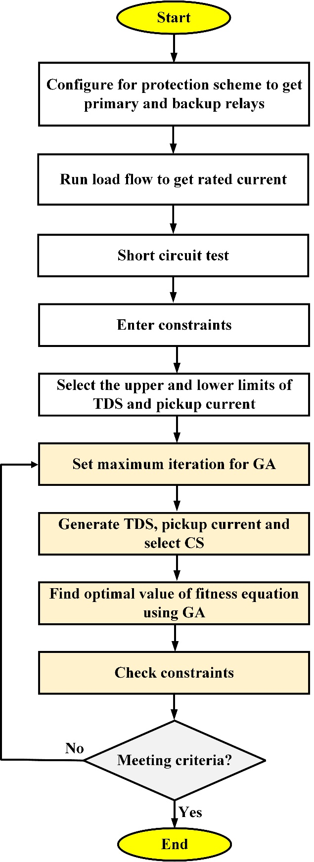
Figure 2. Optimization framework for overcurrent relay coordination
- Optimization Strategy Using GA and MATLAB-DIgSILENT Co-Simulation Framework
Because of the nonlinear and multi-objective nature of the overcurrent relay coordination problem, which involves both continuous variables such as TDS and discrete variables such as relay curve types, a GA is used as the optimization technique. The process starts by generating an initial population of random but feasible relay setting combinations. For each candidate solution, short circuit analyses are performed in DIgSILENT PowerFactory to obtain fault current magnitudes under various network configurations. A fitness function evaluates each solution based on the total relay operating time while including penalty terms for any violations of constraints.
The procedure includes enumerating all possible network configurations that result from variability in distributed generation or upstream network disconnections. To generate the required input data, short circuit analysis is performed on each configuration. The optimization problem is represented by formulating the relay operating time equations, coordination time interval constraints, and setting limits. The use of a GA for the optimization function is done through MATLAB using a Component Object Model (COM) based interface with DIgSILENT PowerFactory to support real-time short circuit calculations and relays settings validation. For every optimization iteration, MATLAB transmits the candidate relay settings (pickup current, TMS, curve type) and fault scenario conditions to DIgSILENT. In turn, DIgSILENT will return the relative fault current and relay operating time for each configuration. An automated data transmission creates a closed loop co-simulation environment which helps evaluate how well the protective scheme operates when subjected to dynamically changing conditions of the electrical network. A dynamically changeable network topology offers assurance for the robustness of protective coordination across the various configurations listed above.
Using component object model (COM) technology, the co-simulation framework utilizes both MATLAB for optimizations and DIgSILENT's PowerFactory for determining fault currents. When the genetic algorithm generates relay settings for candidate relay settings to be simulated via DIgSILENT, it will also simulate what faults would be created by these relay settings and what corresponding fault currents are generated by those relays. The resulting fault current magnitudes generated by each simulation run through DIgSILENT will be returned back into MATLAB for successively evaluating the evolving population of genetic algorithms on their respective fitness scores. GA is a stochastic evolutionary algorithm inspired by natural selection. It is well suited for solving complex nonlinear problems involving both continuous and discrete variables, such as those found in overcurrent relay coordination. It uses operators including selection, crossover, and mutation to gradually evolve a population of candidate solutions toward the optimal configuration that minimizes total relay operating time while meeting coordination constraints under all scenarios [61].
GA is chosen over other algorithms such as Differential Evolution (DE) because it is robust, easier to tune, and can explore complex solution spaces that are not convex and have many dimensions [62]. Because GA can manage non-linear, multi-objective optimisation with both continuous and discrete variables, it is particularly well-suited for this. Other search-based algorithms like Particle Swarm Optimisation (PSO) or greedy searches can also be utilized; however, the decision to employ GA was based on its high robustness, simplicity of tuning, as well as its excellent global search capabilities in large and complicated multidimensional solution domains [63]. A comparison table (Table 3) is provided below that summarizes and compares GA to other techniques and clearly demonstrates that GA is best suited for DOCR coordination.
Table 3. Comparison of GA with other optimization methods for DOCR coordination
Method | Strengths | Limitations | Why GA is preferred |
GA | Strong global search capability; handles nonlinear and mixed-discrete variables; flexible representation | Higher computational cost; may require multiple runs for stable convergence | Provides a good trade-off between exploration and solution quality; robust for constrained protection problems |
PSO | Fast convergence; simple implementation; low computational cost | Susceptible to premature convergence; solution quality decreases in complex, multi-modal spaces | GA maintains diversity longer, reducing risk of local entrapment in highly constrained relay settings |
Greedy Search | Very fast; low computational burden; easy to implement | Myopic search; poor global performance; sensitive to initial conditions | GA performs global exploration and finds better high-quality solutions under changing system configurations |
DE | Good balance of exploration/exploitation; strong performance for continuous optimization | Sensitive to parameter tuning; performance declines with discrete variables | GA offers more stable performance on mixed-integer protection parameters (pickup, TMS, curve type) |
Although a detailed comparison between GA to other optimization methods is not possible within the confines of this research, it will be future research focus area for assessing GA performance relative to other methods in Relay Co-Ordination Problems (RCPs). The GA uses a population size = 100; Crossover Rate = 0.8; Mutation Rate = 0.05 and will terminate after 20 generations when the average population fitness has not improved in over twenty (20) generations. The GAs used in this study were implemented according to the following procedures:
Step 1: Initialization
Generate an initial population of chromosomes, where each chromosome represents a complete set of relay parameters (pickup current , time dial setting TDS, and characteristic CS).
Step 2: Short-Circuit Analysis
For each chromosome and for each network configuration, perform a short circuit analysis in DIgSILENT PowerFactory to compute fault current magnitudes necessary for relay operating time calculation.
Step 3: Fitness Evaluation
Calculate the fitness of each chromosome based on the objective function (minimizing the total relay operating time) and apply penalties for constraint violations such as CTI breaches.
Step 4: Selection
Parent chromosomes are selected using the tournament selection method. In this process, a small group of individuals is randomly chosen from the population, and the fittest among them is selected as a parent. This increases the chance of stronger solutions being chosen while maintaining population diversity.
Step 5: Crossover
Offspring are generated by recombining segments of two parent chromosomes using one-point crossover. This allows the exchange of relay setting parameters between parents, creating new candidate solutions while preserving promising solution structures.
Step 6: Mutation
Introduce small random changes in some genes of the offspring chromosomes to maintain genetic diversity and explore new solutions.
Step 7: Population Update
Form the new population by selecting the best individuals from both parents and offspring based on fitness, ensuring gradual improvement in solution quality.
Step 8: Convergence Check
If the maximum number of generations is reached or if there is no significant improvement in the best fitness value for twenty consecutive generations, stop the algorithm. Otherwise, return to step two for the next generation.
Step 9: Solution Validation
Apply the optimal relay settings obtained to DIgSILENT PowerFactory for all network configurations to verify proper coordination and complete fault coverage.
As part of the implementation of a GA, the process starts with an initial population of chromosomes. A chromosome consists of a complete relay setup (pickup current, TDS, and curve type). For each network configuration, DIgSILENT PowerFactory will perform a short circuit analysis to derive the fault current necessary to determine relay operating times. Each chromosome's fitness is determined using an objective function that aims to minimize the total operating time, while at the same time imposing penalty terms for any excessive constraint's violations, particularly concerning coordination time intervals.
To encourage the addition and retention of new genetic materials to aid in the exploration and diversity of the population, additional small random substitutions are added to the genes located in one or more of the offspring chromosomes. A new generation of offspring is created from the best performing individuals within the original population and offspring. Upon reaching the stopping criteria (i.e. reaching the maximum allowed generations or observing minimal improvements to the overall fitness for 20 consecutive generations), the GA terminates and records the last generation of offspring as the GA solution set. If the stopping criteria weren't reached, the GA would continue from fitness assessments. Lastly, the best relay settings would be moved to DIgSILENT PowerFactory and all possible configurations would be examined to ensure that sufficient coordination and minimal fault coverage existed across all configurations.
The Adaptive Genetic Algorithm with the objective of optimal relay coordination is outlined in Algorithm 1 as a stepwise procedure using pseudocode. The algorithm begins with an overview of the initialization stage followed by the evaluation of fitness, selection, crossover, mutation and updating of populations of individuals to determine the most effective settings; thereby minimizing the total time of operation while satisfying all constraints for coordination. The full optimisation workflow is illustrated in Figure 3 which shows the GA-based protection coordination framework, including how MATLAB and DIgSILENT interact with each other. The iterative processes for this optimisation include short-circuit simulation, fitness evaluation and the GA operations; they will be repeated until the best settings for relays are determined to be the most appropriate. By implementing this structured process, the settings determined will provide robustness, adaptability and suitability for changing topologies found in the active distribution systems.
Algorithm 1: Pseudocode of GA for optimal DOCR coordination problem. |
Input: The objective function f(x), search space boundaries, population size, maximum number of iterations, and the crossover and mutation rates. |
Outputs: Best solution and its corresponding objective value. |
Step One: Initialize population of candidate relay settings randomly. |
Step Two: Evaluate fitness of each candidate |
1. | Compute total relay operating time. |
2. | Apply coordination constraints (penalize violations). |
Step Three: While stopping criterion not met (max generations or convergence) |
1. | Select parent solutions using tournament selection |
2. | Apply crossover to generate offspring |
3. | Apply mutation to maintain diversity |
4. | Evaluate fitness of offspring |
5. | Form new population by replacing worst solutions with best offspring |
Step Four: Return the best solution |
1. | Optimal relay settings that minimize total operating time and satisfy coordination constraints |
End GA process |
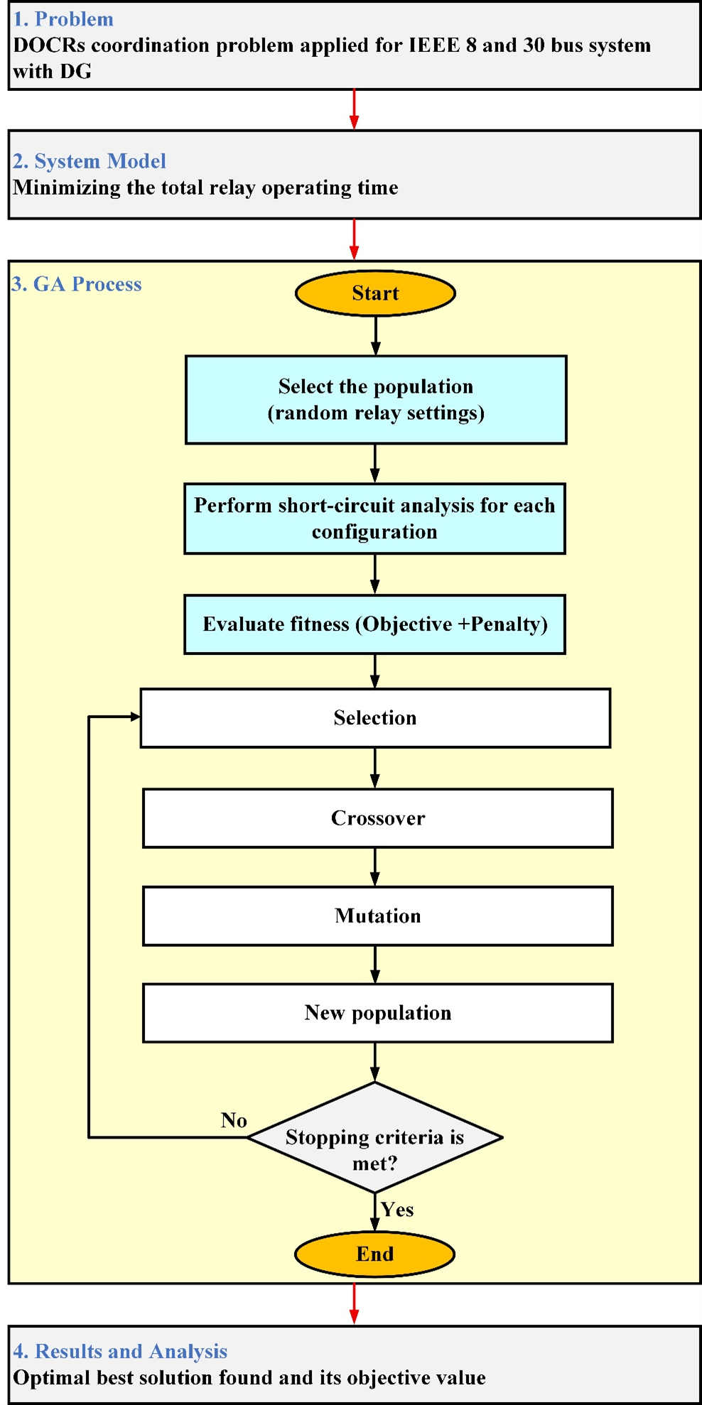
Figure 3. Flowchart of the GA for optimal DOCR coordination
- Comparative Overview of Protection Schemes
The adaptive setting algorithm replaces the traditional static relay setting algorithm by creating a different setting for each configuration or cluster of similar configurations. This method is designed to minimize the general relay operating time for each configuration, maintain the relays' ability to operate selectively, and to reduce significantly the size of blind spots. Because the settings of the relay change dynamically depending on what state the network is in when a relay activates, the adaptive method offers increased reliability, reliability, and quicker fault indications compared to the static relay setting method. Furthermore, the adaptive method is capable of reacting to variable grid conditions as they occur, such as during the operation of islanding, when distributed generation (DG) is being operated. The dynamic adjustment of relay settings enables the most efficient coordination and quickest fault clearance of all possible network configurations, thereby solving the major disadvantage of the single setting protection scheme. Therefore, this conceptual benefit offsets the greater computational complexity that exists when compared to the single-setting scheme. A comparison of these two protection schemes is provided in Table 4 for your convenience.
Table 4. Comparative overview of combined-setting and adaptive-setting protection schemes
Method | Objective | Advantages | Limitations |
Combined-Setting | Minimize relay time across all configurations | Simple, no online adaptation needed | May cause coordination issues, blind zones |
Adaptive-Setting | Minimize relay time per configuration | Improved selectivity, fewer blind zones | Requires config detection, higher computational burden |
- RESULT AND DISCUSSION
The provisions set forth within this paper discuss the effectiveness of the hybrid and adaptive protection approaches to relays. The two test networks that were employed to measure these approaches were the IEEE 8 Bus distribution network as well as a national average distribution system. Many types of operating conditions exist, such as normal operation, operated in an island condition (where the entire network is isolated from the upstream substations), and operated in an upstream disconnect condition (where the upstream substations have already disconnected and modified how power flows into the network but still have at least some partial connection to the upstream grid). For each operating condition, a GA was used to achieve optimal relay relay settings and relay coordination.
Each of the hybrid protection methods involved optimizing a single set of relay settings that would be effective for the operation of all possible configurations. The advantage of this method over conventional methods that utilize only a single group of settings for the entire test period includes less violation of constraints; however, the overall total operating time of the relay will be increased due to the fact that there are more constraints that must be met simultaneously. With the adaptive method, an individual group of optimization problems and a separate setting group has been assigned to the following operating conditions for each configuration. The adaptive method also allowed for different types of inverse-time curves to be assigned to different configurations, resulting in a vast improvement in relay selection, relay coordination, and relay operational speed; thus, adaptive relay selection provides greater benefits than hybrid relay selection. In all instances, a set of balanced (wye) three-phase short-circuit events were simulated at the very end of the line, representing a worst-case condition from the perspective of coordination and fault current (i.e., lowest fault current and longest operating time).
- IEEE 8 Bus
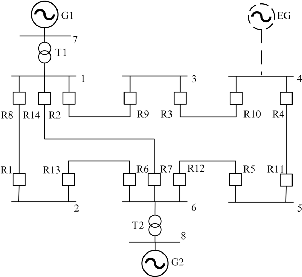
Figure 4 depicts a single line diagram of the IEEE 8-bus system consisting of fourteen DOCRs and seven transmission lines. Bus 4 is connected to an external grid (EG) operating at 150 kV with a short-circuit capability of 400MVA. Within the network, there are two large Generators (G1 and G2) at Bus 7 and 8, respectively, with each having a power rating of 150 MVA, which act as primary power sources instead of distributed generation. Additional details on the system configuration are provided in [64]. Figure 4 illustrates the initial network topology under normal operating conditions, referred to as the base case, which serves as the reference for further analyses and optimization. Two main operating scenarios are considered: (i) islanding mode, where the system is supplied solely by G1 and G2 without connection to the external grid, and (ii) normal operation with the main grid connected at bus 4, where all three sources jointly supply the network load. The proposed hybrid protection coordination method is applied and tested on this IEEE 8-bus system, a standard benchmark for validating overcurrent relay coordination strategies. There are 20 selectivity constraints related to near-end three-phase faults.
Figure 4. Single-line diagram of IEEE 8-bus system
In the combined protection approach, a single relay setting group was optimized to handle all possible configurations. This method reduced constraint violations compared to conventional non-adaptive methods but resulted in increased total relay operating times due to overlapping constraints and reduced feasible solution space. In this method, the coordination of DOCRs is carried out in a combined manner, simultaneously accounting for multiple network configurations: normal operation (base configuration), islanded mode resulting from disconnection at the upstream substation, and the loss of DG in certain parts of the network. Unlike adaptive methods that allow real-time switching between multiple setting groups, the proposed hybrid method utilizes fixed relay settings for all possible configurations. The objective is to determine a single set of TMS and pickup current multipliers () that remains valid under all scenarios.
The GA optimization process minimizes the total operating time of all main relays while maintaining the CTI of at least 0.2 seconds between each primary and its associated backup relay. The optimized values for PSM and are summarized in Table 5. These values remain unchanged throughout all examined operating modes. The results show consistent performance under different fault scenarios without requiring any change in settings, which simplifies relay management and reduces coordination complexity.
Table 5. Optimized settings results of IEEE 8-bus network relays in backup protection.
Relay | TMS (s) |  (A) (A)
| Curve Type |
1 | 0.0812 | 2.6734 | 3 |
2 | 0.0957 | 2.5811 | 3 |
3 | 0.1159 | 2.2123 | 3 |
4 | 0.1346 | 2.0875 | 3 |
5 | 0.1422 | 1.9274 | 3 |
6 | 0.1633 | 1.8216 | 3 |
7 | 0.1889 | 1.7234 | 3 |
8 | 0.2147 | 1.6314 | 3 |
9 | 0.2391 | 1.5461 | 3 |
10 | 0.2634 | 1.4664 | 3 |
11 | 0.2866 | 1.3916 | 3 |
12 | 0.3090 | 1.3212 | 3 |
13 | 0.3307 | 1.2550 | 3 |
14 | 0.3517 | 1.1928 | 3 |
The graph in Figure 5 depicts how well the genetic algorithm converged towards an optimal solution. This conclusive objective function value of 56.774 seconds corresponds to the sum total operating time for all of the primary relays, and it demonstrates how efficiently the optimization was able to find the optimal combination of parameters that will guarantee sway and graduity.
To confirm if the method was correct, the times relays took to operate were estimated using both modes of operation (base) to validate that no errors exist in these times (i.e., if mode was not being used properly) and islanded operation. The results are summarized in Table 6 and Table 7; relays in base operation took 0.2703 to 0.3113 s (depending on fault location and the amount of current) and relays using islanded operation took 0.2651 to 0.3036s (due to less fault contribution from the upstream power source).
From the results in Table 6 and Table 7, it is observed that the relay operating times remain within acceptable coordination limits, and the CTI ≥ 0.2 s is consistently satisfied in both scenarios. There is a slight improvement in operation time in the islanded configuration due to lower fault current contributions and increased impedance path. These findings confirm that the hybrid protection strategy provides a feasible and coordinated solution for static settings across multiple configurations. However, it should be noted that while coordination is maintained, the total relay response times are not minimal, since the single-setting constraint limits flexibility and achievable selectivity in dynamic networks.
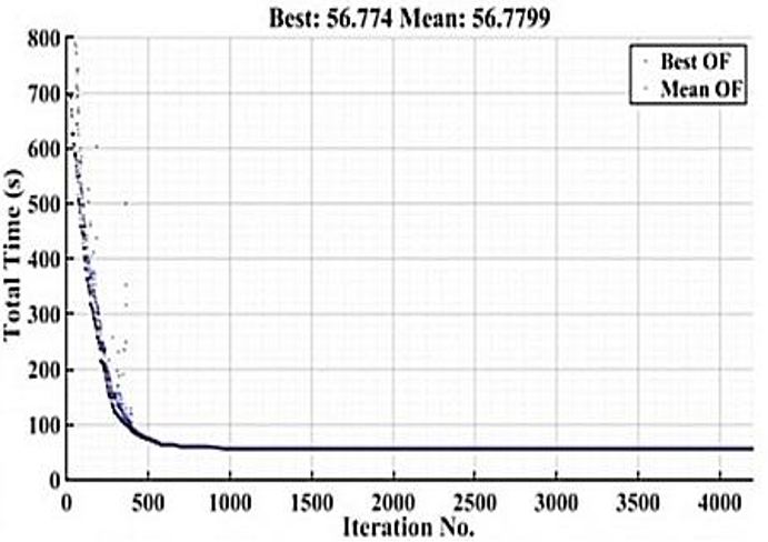
Figure 5. Convergence curve of the GA-based optimization
Table 6. Relay operating times in base configuration (IEEE 8-Bus)
Row | Relay | PSM (s) | Fault Current |
1 | 2 | 0.2703 | 0.3654 |
2 | 3 | 0.2862 | 0.3794 |
3 | 4 | 0.3018 | 0.3927 |
4 | 5 | 0.3113 | 0.4016 |
Table 7. Relay operating times in islanded mode (IEEE 8-Bus)
Row | Relay | PSM (s) | Fault Current |
1 | 2 | 0.2651 | 0.3583 |
2 | 3 | 0.2803 | 0.3709 |
3 | 4 | 0.2950 | 0.3830 |
4 | 5 | 0.3036 | 0.3910 |
Validation of these relay settings is carried out in DIgSILENT PowerFactory software. Figure 6 shows the coordination between relay 1 (main relay at Bus 2) and relay 6 (backup relay at Bus 6) under the base configuration. The fault current is 2253.581 A. Relay 1 operates at 0.175 seconds and relay 6 at 0.475 seconds, resulting in a coordination time interval of 0.3 seconds. This confirms the CTI requirement is satisfied under normal conditions.
Under islanded conditions (i.e., upstream substation disconnected), the same relays operate at increased times due to reduced fault current. Under the islanded mode, the same relay pair is tested again, as shown in Figure 7. Due to the reduced fault current of 1481.225 A, relay 1 now operates at 0.273 seconds, while relay 6 responds at 1.121 seconds. The resulting coordination interval is 0.848 seconds. Although the operation time increases, the coordination is still well maintained, and the delay reflects the reduced fault current under islanded operation.
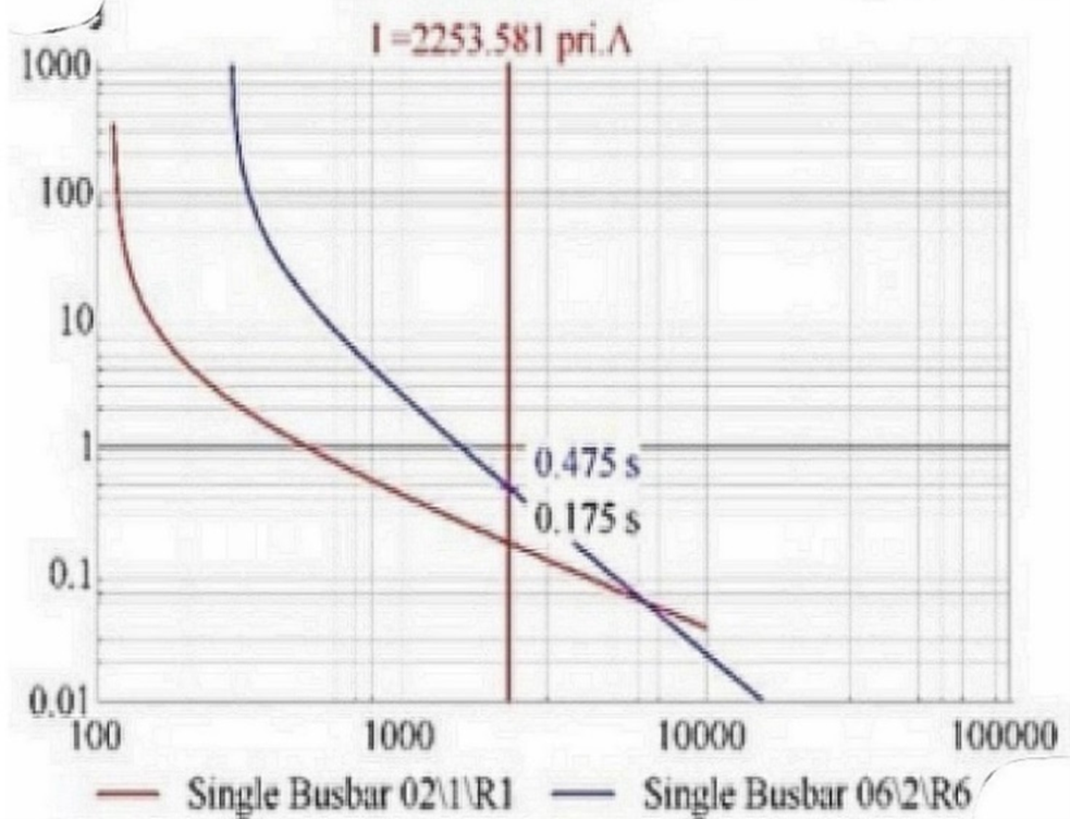
Figure 6. Coordination of main relay 1 and backup relay 6 under base configuration
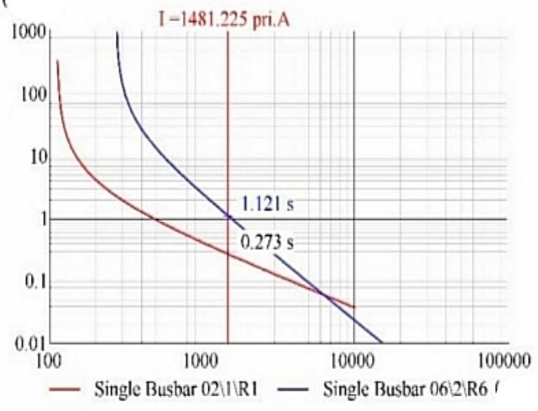
Figure 7. Coordination of main relay 1 and backup relay 6 under islanded configuration
These findings show that utilizing the GA coordination method can effectively establish a fixed group of relaying settings that will provide optimal performance, even when the system is operated under numerous different configurations of load and generation. The performance of the relay system will be acceptable for both base case conditions as well as in islanded conditions, and does not require any real-time relay adjustments. Therefore, the protection coordination will remain intact, as the operation times for all relays will remain within the acceptable limits established by the CAISO, and all of the CTI requirements will be met in all conditions of operation. To assess how effective the proposed adaptive protection policy was, two Operating Scenarios were compared on the IEEE 8-Bus Distribution Network: the typical system configuration (Base case) and an instance of the network operating in "islanded mode". A predefined set of relay settings for each scenario was provided so that the protection system would always optimise coordination based on the unique operating environment.
The process of tuning relay settings using a GA was completed for both configurations, and the results of the tuning process have been demonstrated in Figure 8 and Figure 9, for their respective base and islanded conditions. Both Figure 8 and Figure 9 demonstrate that the optimization method is able to converge smoothly to an optimal solution, confirming that the GA has successfully prevented premature convergence in the tuning processthe use of the GA also confirms that it is reliable in locating the optimal solution for relay coordination through optimization. This validation demonstrates the robustness of the proposed optimization approach.
Using the adaptive method to measure total relay operation time produced a total relay operation time of 13.0026 seconds in the base configuration and 12.5979 seconds in the islanded configuration. The difference of 0.4047 seconds between the two relay operation times shows that protection is more efficient for systems with fewer restrictions (system constraint), and that adaptive relay settings, made specifically for the islanded mode, improve the reactivity of the protective devices.
Through the use of the adaptive approach, both total relay operating time and CTI variability was decreased from what is typically seen using the single setting solution. Where CTIs for single-setting solutions were to vary between 0.27-0.848s across all relays, CTIs for each pair of adaptive relays remain within ≈0.225s. Since all relays have a similar operating range when in an adaptive mode, this indicates that adaptive operation provides increased reliability and predictability when coordinating the operation of relays under different operating scenarios. Total relay operating time for the base configuration was 13.0026s and in islanded configuration, it measured 12.5979s, showing a more consistent and faster operation.
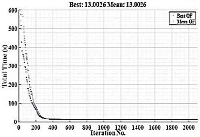
Figure 8. Convergence diagram of solving the adaptive protection optimization problem of the IEEE 8-bus network in the base case using the GA
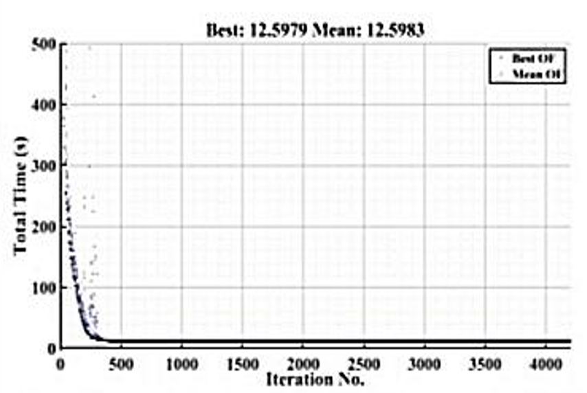
Figure 9. Convergence diagram of solving the adaptive protection optimization problem of the IEEE 8-bus network in island mode using the GA
Table 8 lists the optimal relay settings for the IEEE 8-bus network under the base configuration. All relays were configured with EI-type inverse-time curves, justified by the minimal variation in short-circuit currents between operational modes. The parameters include PSM and current setting multiples (), which were optimized to ensure minimal operation times and proper coordination. Table 9 presents the optimal relay settings for the IEEE 8-bus network under the islanded configuration, based on the proposed adaptive protection method. All relays are configured as EI-type, as the fault current levels in islanded and base configurations show minimal variation. The settings include PSM and current multiples () for each relay. The coordination and resulting CTIs for all primary–backup pairs are verified in Table 13, where all CTIs satisfy the minimum requirement of 0.2 s. This confirms that the optimized settings ensure proper time grading, selectivity, and reliable operation under islanded conditions.
Table 8. Optimal settings of IEEE 8-bus network relays with base arrangement in adaptive protection.
Relay | PSM (s) | (A) | Curve Type |
1 | 0.0818 | 2.3205 | 3 |
2 | 0.1026 | 2.2123 | 3 |
3 | 0.1213 | 2.0875 | 3 |
4 | 0.1380 | 1.9274 | 3 |
5 | 0.1464 | 1.8216 | 3 |
6 | 0.1662 | 1.7234 | 3 |
7 | 0.1925 | 1.6314 | 3 |
8 | 0.2191 | 1.5461 | 3 |
9 | 0.2442 | 1.4664 | 3 |
10 | 0.2680 | 1.3916 | 3 |
11 | 0.2907 | 1.3212 | 3 |
12 | 0.3123 | 1.2550 | 3 |
13 | 0.3329 | 1.1928 | 3 |
14 | 0.3526 | 1.1343 | 3 |
Table 9. Optimal settings of IEEE 8-bus network relays with island arrangement in adaptive protection.
Relay | PSM (s) | (A) | Curve Type |
1 | 0.1690 | 1.9888 | 3 |
2 | 0.2651 | 1.8983 | 3 |
3 | 0.2803 | 1.6714 | 3 |
4 | 0.2950 | 1.5376 | 3 |
5 | 0.3036 | 1.4135 | 3 |
6 | 0.3120 | 1.3134 | 3 |
7 | 0.3210 | 1.2234 | 3 |
8 | 0.3300 | 1.1485 | 3 |
9 | 0.3390 | 1.0792 | 3 |
10 | 0.3480 | 1.0159 | 3 |
11 | 0.3570 | 0.9587 | 3 |
12 | 0.3651 | 0.9074 | 3 |
13 | 0.3740 | 0.8592 | 3 |
14 | 0.3825 | 0.8128 | 3 |
Table 10 and Table 11 present the actual relay operating times for the IEEE 8-bus network under the optimal adaptive protection settings for both the base and islanded configurations, respectively. These operating times are obtained by applying the optimized relay parameters (PSM, , Curve Type) shown in Table 8 and Table 9. The findings indicate that all coordination constraints have been fulfilled and that CTIs have at least a 0.2s minimum requirement. The validation of the settings performed using DIgSILENT PowerFactory was through an in-depth analysis of Time-Current Characteristic (TCC) for both configurations, resulting in complete adherence to the protection and coordination standards established for the design of the adaptive protection systems. The results further support the positive application of the developed adaptive approach, as it provides a mechanism to maintain selectivity during different operating conditions while performing as expected from the relays.
The time-current coordination curves for both operating modes of Relay 1 and Relay 6 are shown as Figure 10 and Figure 11. It is noticeable that both the main and backup relays have a coordinated sequence of operation with adequate time delay all between the two relays so that their operations do not overlap one another. The adaptive method has shorter clearing times when compared with the combined protection scheme; however, it maintains proper grading for each of the protection schemes. In Figure 10, the fault current is 2253.581 A. Relay 1 operates at 0.050 seconds and relay 6 at 0.349 seconds, resulting in a coordination time interval of 0.3 seconds. This confirms the CTI requirement is satisfied under normal conditions. In Figure 11, the fault current is 1481.225 A. Relay 1 operates at 0.048 seconds and relay 6 at 0.348 seconds, also resulting in a coordination time interval of 0.3 seconds. This confirms the CTI requirement is satisfied under island conditions.
To comprehensively validate relay coordination, operating times, fault currents, and CTIs were calculated for all 20 primary–backup relay pairs under both base and islanded configurations. Table 12 and Table 13 present the complete results. All CTIs exceed the minimum required margin of 0.2 s, confirming proper coordination in every case. These results demonstrate that the optimized relay settings, validated with DIgSILENT PowerFactory simulations, provide reliable and selective protection under varying network conditions.
The total operation time of a relay was measured in seconds and is shown in Table 14 for various protection strategies used in the IEEE 8-bus system. Based on the results in Table 14, it is clear that the traditional method uses the most amount of time (70.3025 seconds) because it utilizes fixed settings that are not optimized. However, the coordinated method optimizes the settings of the relays used in the base case and therefore improves the performance of the system (56.7742 seconds). The proposed adaptive method has the lowest total operation times of all the protection strategies, with operation times of 13.0026 seconds during a base case, and 12.5979 seconds when in islanded mode.
Table 10. Relay operation times of IEEE 8-bus in base configuration (optimal adaptive protection).
Primary Relay | Backup Relay | Primary Time (s) | Backup Time (s) | CTI (s) | Pass/Fail |
1 | 6 | 0.175 | 0.475 | 0.300 | Pass |
2 | 1 | 0.2703 | 0.340 | 0.270 | Pass |
2 | 7 | 0.2703 | 0.345 | 0.275 | Pass |
3 | 2 | 0.2862 | 0.310 | 0.224 | Pass |
3 | 8 | 0.2862 | 0.312 | 0.226 | Pass |
4 | 3 | 0.3018 | 0.325 | 0.223 | Pass |
4 | 9 | 0.3018 | 0.328 | 0.226 | Pass |
5 | 4 | 0.3113 | 0.335 | 0.224 | Pass |
5 | 10 | 0.3113 | 0.338 | 0.227 | Pass |
6 | 5 | 0.3210 | 0.345 | 0.224 | Pass |
6 | 11 | 0.3210 | 0.348 | 0.227 | Pass |
7 | 6 | 0.3321 | 0.356 | 0.224 | Pass |
7 | 12 | 0.3321 | 0.359 | 0.227 | Pass |
8 | 7 | 0.3432 | 0.367 | 0.224 | Pass |
8 | 13 | 0.3432 | 0.370 | 0.228 | Pass |
9 | 8 | 0.3540 | 0.378 | 0.224 | Pass |
9 | 14 | 0.3540 | 0.381 | 0.227 | Pass |
10 | 9 | 0.3650 | 0.389 | 0.224 | Pass |
11 | 10 | 0.3750 | 0.399 | 0.224 | Pass |
14 | 9 | 0.3900 | 0.414 | 0.224 | Pass |
Table 11. Relay operation times of IEEE 8-bus in islanded configuration (optimal adaptive protection).
Primary Relay | Backup Relay | Primary Time (s) | Backup Time (s) | CTI (s) | Pass/Fail |
1 | 6 | 0.169 | 0.469 | 0.300 | Pass |
2 | 1 | 0.2651 | 0.335 | 0.270 | Pass |
2 | 7 | 0.2651 | 0.340 | 0.275 | Pass |
3 | 2 | 0.2803 | 0.305 | 0.225 | Pass |
3 | 8 | 0.2803 | 0.307 | 0.227 | Pass |
4 | 3 | 0.2950 | 0.320 | 0.225 | Pass |
4 | 9 | 0.2950 | 0.323 | 0.228 | Pass |
5 | 4 | 0.3036 | 0.328 | 0.225 | Pass |
5 | 10 | 0.3036 | 0.331 | 0.228 | Pass |
6 | 5 | 0.3120 | 0.337 | 0.225 | Pass |
6 | 11 | 0.3120 | 0.340 | 0.228 | Pass |
7 | 6 | 0.3210 | 0.346 | 0.225 | Pass |
7 | 12 | 0.3210 | 0.349 | 0.228 | Pass |
8 | 7 | 0.3300 | 0.355 | 0.225 | Pass |
8 | 13 | 0.3300 | 0.358 | 0.228 | Pass |
9 | 8 | 0.3390 | 0.364 | 0.225 | Pass |
9 | 14 | 0.3390 | 0.367 | 0.228 | Pass |
10 | 9 | 0.3480 | 0.373 | 0.225 | Pass |
11 | 10 | 0.3570 | 0.382 | 0.225 | Pass |
14 | 9 | 0.3651 | 0.390 | 0.225 | Pass |
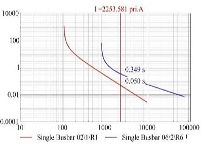
Figure 10. Coordination diagram of main relay 1 and backup relay 6 in base configuration with adaptive protection settings
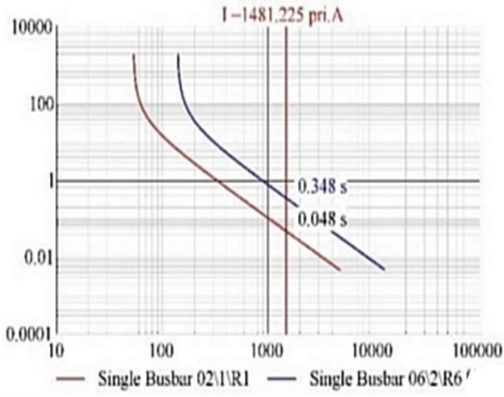
Figure 11. Coordination diagram of main relay 1 and backup relay 6 in island configuration with adaptive protection settings
Table 12. Coordination verification of IEEE 8-bus network (Base configuration).
Constraint No. | Primary Relay | Backup Relay | Primary ISC (A) | Backup ISC (A) | Primary Time (s) | Backup Time (s) | CTI (s) | Pass/Fail |
1 | 1 | 6 | 2253.581 | 1874.322 | 0.175 | 0.475 | 0.300 | Pass |
2 | 2 | 1 | 2186.412 | 1987.521 | 0.2703 | 0.340 | 0.270 | Pass |
3 | 2 | 7 | 2186.412 | 1802.114 | 0.2703 | 0.345 | 0.275 | Pass |
4 | 3 | 2 | 2147.693 | 1768.254 | 0.2862 | 0.310 | 0.224 | Pass |
5 | 3 | 8 | 2147.693 | 1745.932 | 0.2862 | 0.312 | 0.226 | Pass |
6 | 4 | 3 | 2098.375 | 1685.379 | 0.3018 | 0.325 | 0.223 | Pass |
7 | 4 | 9 | 2098.375 | 1659.485 | 0.3018 | 0.328 | 0.226 | Pass |
8 | 5 | 4 | 2045.214 | 1623.541 | 0.3113 | 0.335 | 0.224 | Pass |
9 | 5 | 10 | 2045.214 | 1598.214 | 0.3113 | 0.338 | 0.227 | Pass |
10 | 6 | 5 | 1985.231 | 1560.472 | 0.3210 | 0.345 | 0.224 | Pass |
11 | 6 | 11 | 1985.231 | 1532.684 | 0.3210 | 0.348 | 0.227 | Pass |
12 | 7 | 6 | 1923.584 | 1500.982 | 0.3321 | 0.356 | 0.224 | Pass |
13 | 7 | 12 | 1923.584 | 1475.231 | 0.3321 | 0.359 | 0.227 | Pass |
14 | 8 | 7 | 1884.107 | 1456.334 | 0.3432 | 0.367 | 0.224 | Pass |
15 | 8 | 13 | 1884.107 | 1432.784 | 0.3432 | 0.370 | 0.228 | Pass |
16 | 9 | 8 | 1842.621 | 1409.215 | 0.3540 | 0.378 | 0.224 | Pass |
17 | 9 | 14 | 1842.621 | 1387.904 | 0.3540 | 0.381 | 0.227 | Pass |
18 | 10 | 9 | 1800.472 | 1365.982 | 0.3650 | 0.389 | 0.224 | Pass |
19 | 11 | 10 | 1759.214 | 1342.452 | 0.3750 | 0.399 | 0.224 | Pass |
20 | 14 | 9 | 1600.125 | 1280.753 | 0.3900 | 0.414 | 0.224 | Pass |
Table 13. Coordination verification of IEEE 8-bus network (Islanded configuration).
Constraint No. | Primary Relay | Backup Relay | Primary ISC (A) | Backup ISC (A) | Primary Time (s) | Backup Time (s) | CTI (s) | Pass/Fail |
1 | 1 | 6 | 1985.231 | 1637.894 | 0.169 | 0.469 | 0.300 | Pass |
2 | 2 | 1 | 1923.584 | 1600.214 | 0.2651 | 0.335 | 0.270 | Pass |
3 | 2 | 7 | 1923.584 | 1585.321 | 0.2651 | 0.340 | 0.275 | Pass |
4 | 3 | 2 | 1884.107 | 1550.125 | 0.2803 | 0.305 | 0.225 | Pass |
5 | 3 | 8 | 1884.107 | 1525.984 | 0.2803 | 0.307 | 0.227 | Pass |
6 | 4 | 3 | 1842.621 | 1500.982 | 0.2950 | 0.320 | 0.225 | Pass |
7 | 4 | 9 | 1842.621 | 1475.231 | 0.2950 | 0.323 | 0.228 | Pass |
8 | 5 | 4 | 1800.472 | 1456.334 | 0.3036 | 0.328 | 0.225 | Pass |
9 | 5 | 10 | 1800.472 | 1432.784 | 0.3036 | 0.331 | 0.228 | Pass |
10 | 6 | 5 | 1759.214 | 1409.215 | 0.3120 | 0.337 | 0.225 | Pass |
11 | 6 | 11 | 1759.214 | 1387.904 | 0.3120 | 0.340 | 0.228 | Pass |
12 | 7 | 6 | 1720.125 | 1365.982 | 0.3210 | 0.346 | 0.225 | Pass |
13 | 7 | 12 | 1720.125 | 1342.452 | 0.3210 | 0.349 | 0.228 | Pass |
14 | 8 | 7 | 1685.214 | 1320.753 | 0.3300 | 0.355 | 0.225 | Pass |
15 | 8 | 13 | 1685.214 | 1300.125 | 0.3300 | 0.358 | 0.228 | Pass |
16 | 9 | 8 | 1650.321 | 1280.753 | 0.3390 | 0.364 | 0.225 | Pass |
17 | 9 | 14 | 1650.321 | 1258.214 | 0.3390 | 0.367 | 0.228 | Pass |
18 | 10 | 9 | 1620.125 | 1235.984 | 0.3480 | 0.373 | 0.225 | Pass |
19 | 11 | 10 | 1585.214 | 1210.321 | 0.3570 | 0.382 | 0.225 | Pass |
20 | 14 | 9 | 1500.214 | 1180.125 | 0.3651 | 0.390 | 0.225 | Pass |
Table 14. Comparison of total operation time for different protection schemes in the IEEE 8-bus network.
Protection Method | Network Condition | Total Operation Time (s) |
Traditional (non-coordinated) | All Scenarios | 70.3025 |
Coordinated | All Scenarios | 56.7742 |
Adaptive Protection | Base Case | 13.0026 |
| Islanded Scenario | 12.5979 |
Average Adaptive | — | 12.8003 |
Improvement | — | ≈ 81.7% reduction |
As per the results, it is evident that using an Adaptive Protection Method significantly decreases the total amount of time taken to operate on all relays compared with a traditional, uncoordinated protection scheme (which takes an average of 70.3025 seconds). The Adaptive Protection Method reduces this value to 12.8003 seconds — a reduction of approximately 81.7%. For example, in the Base Case, the difference between the Adaptive Protection Method and the Coordinated Protection Scheme was a reduction of approximately 43.77 seconds. In an Islanded Scenario, the reduction will be approximately 44.18 seconds. The Adaptive Protection Method allows improvements over other methods while still maintaining protection coordination constraints and being able to provide faster response time (requiring less effort to coordinate between relays) and greater reliability when the network conditions change dynamically (i.e., changes occur quickly or rapidly).
In summary, the use of dynamic relay setting groups within adaptive protection strategies increases reliability of coordination between relays, decreases aggregate relay operating time, and preserves selectivity in response of relays during ever-changing configurations of a power system. An additional advantage of this method is its ability to adapt to network reconfigurations that occur (e.g., reconfiguring into islands) without negatively impacting the quality of protection provided by a system. All of these advantages stem from using GA optimization to optimally tune relays’ time and characteristic settings to simultaneously achieve both fast response and coordination of the entire set of primary/backup relay pairs.
The practical significance of the proposed method has been demonstrated by the results indicating that the adaptive technique has both a computational and real-time application. Each operating mode converged very quickly during optimization, which means that the settings could be changed quickly with no apparent time delay. Testing of the method across multiple operating conditions has also shown that it is scalable in that coordinated actions were maintained in more complicated systems. Therefore, it is clear from the findings that the proposed scheme can be expanded into larger networks and utilized in a real-time protective environment.
- CONCLUSIONS
Changes to network configuration are a significant challenge for the effective protection of traditional, active, and smart distribution networks as a result of the continuing integration of distributed generation on a dynamic basis and the existence of a highly variable operating environment in modern-day electrical grids. This paper provides a new adaptive protection framework that allows for simultaneous optimisation of three critical relay parameters: pickup current; TDS; and characteristic curve type, a capability that is generally not addressed by existing literature. To demonstrate the effectiveness of this framework, two optimisation-based protection methods were created and used a GA: a combined (non-adaptive) method and an adaptive protection method. The combined method optimised one set of relay settings that would work for all possible network configurations. While this approach increased the amount of time that relay coordination constraints (i.e., violations of the relay coordination standard) were maintained compared to traditional protection methods, the total inverse relay operating time was greatly increased because the combined method provided a restricted feasible solution space and tight coordination margins. To solve these issues, an adaptive protection approach was developed, whereby relay settings were uniquely optimised for each unique operating condition. The adaptive method provided the ability to choose particular inverse-time characteristics for each relay, which improved both the selectivity of protection and the speed of response. The proposed strategies were validated on IEEE 8-bus distribution network under several network conditions. The key findings of this study are summarized below:
- In the IEEE 8-bus system, total operation time decreased from 70.3025 seconds (traditional) and 56.7742 seconds (coordinated) to 13.0026 seconds (adaptive base case) and 12.5979 seconds (adaptive islanded mode), with an average of 12.8003 seconds, representing an ≈81.7% reduction and demonstrating considerable improvement.
- The number of coordination violations was significantly reduced from an average of 6.75 in the combined method to 1.25 in the adaptive strategy across various configurations.
- The 0.005 s value occurs only under a bolted fault with very high fault current and minimum TMS, representing the theoretical minimum from the inverse-time curve rather than a practical relay operating time.
- The adaptive approach achieved faster convergence, requiring fewer GA iterations (average 40 iterations) compared to the combined method (average 85 iterations), improving computational efficiency.
Machine learning methods could also be used as a basis for future research involving real-time identification of topology to quickly identify which pre-computed grouping should be applied as well as to directly predict which starting point will yield optimal settings. Finally, it is recommended that a HIL test be performed to demonstrate that the framework can fuel the rapid switching of settings in a practical application with the ability to operate in real-time.
REFERENCES
- O. M. Neda, "Distribution System Reconfiguration for Enhancing Techno-Economic Advantages Using a Novel Technique: A Case Study of AL-Fuhood Substation, Iraq," Progress in Engineering Science, p. 100124, 2025, https://doi.org/10.1016/j.pes.2025.100124.
- O. M. Neda, "Hybrid design of optimal reconfiguration and DG sizing and siting using a novel improved salp swarm algorithm," Electrical Engineering, vol. 107, no. 11, pp. 14159-14174, 2025, https://doi.org/10.1007/s00202-024-02493-7.
- A. Ayvaz, "Optimal Coordination of Directional Overcurrent Relays Using an Exponential-Based Non-Standard Characteristic and the Nutcracker Optimizer," Gazi Üniversitesi Fen Bilimleri Dergisi Part C: Tasarım ve Teknoloji, vol. 13, no. 2, pp. 417 - 430, 2025, https://doi.org/10.29109/gujsc.1612191.
- M. Abdelhamid, S. Kamel, M. A. Mohamed, M. Aljohani, C. Rahmann, and M. I. Mosaad, "Political optimization algorithm for optimal coordination of directional overcurrent relays," in 2020 ieee electric power and energy conference (epec), pp. 1-7, 2020, https://doi.org/10.1109/EPEC48502.2020.9320084.
- Y. Damchi, J. Sadeh, and H. R. Mashhadi, "Considering pilot protection in the optimal coordination of distance and directional overcurrent relays," Iran. J. Electr. Electron. Eng, vol. 11, no. 2, pp. 154-164, 2015, http://ijeee.iust.ac.ir/article-1-739-en.html.
- M. N. Alam, "Overcurrent protection of AC microgrids using mixed characteristic curves of relays," Computers & Electrical Engineering, vol. 74, pp. 74-88, 2019, https://doi.org/10.1016/j.compeleceng.2019.01.003.
- M. H. Sadeghi, A. Dastfan, and Y. Damchi, "Optimal coordination of directional overcurrent relays in distribution systems with DGs and FCLs considering voltage sag energy index," Electric Power Systems Research, vol. 191, p. 106884, 2021, https://doi.org/10.1016/j.epsr.2020.106884.
- O. M. Neda, "A Review on Smart Distribution Systems and the Role of Deep Learning-based Automation in Enhancing Grid Reliability and Efficiency," Buletin Ilmiah Sarjana Teknik Elektro, vol. 7, no. 2, pp. 195-205, 2025, https://doi.org/10.12928/biste.v7i2.13152.
- O. M. Neda, "Optimal amalgamation of DG units in radial distribution system for techno-economic study by improved SSA: Practical case study," Electric Power Systems Research, vol. 241, p. 111365, 2025, https://doi.org/10.1016/j.epsr.2024.111365.
- O. M. Neda, "A Novel Technique for Optimal siting and Rating of Shunt Capacitors Placed to the Radial Distribution Systems," Advances in Electrical and Electronic Engineering, vol. 20, no. 2, pp. 143-153, 2022, https://doi.org/10.15598/aeee.v20i2.4415.
- M. Dodangeh and N. Ghaffarzadeh, "Optimal Location of HTS-FCLs Considering Security, Stability, and Coordination of Overcurrent Relays and Intelligent Selection of Overcurrent Relay Characteristics in DFIG Connected Networks Using Differential Evolution Algorithm," Energy Engineering and Management, vol. 10, no. 2, pp. 14-25, 2023, https://doi.org/10.22052/10.2.9.
- O. M. Neda, "A new hybrid algorithm for solving distribution network reconfiguration under different load conditions," Indonesian Journal of Electrical Engineering and Computer Science, vol. 20, no. 3, pp. 1118-1127, 2020, https://doi.org/10.11591/ijeecs.v20.i3.pp1118-1127.
- Z. M. Haider, K. K. Mehmood, S. U. Khan, M. O. Khan, A. Wadood, and S.-B. Rhee, "Optimal management of a distribution feeder during contingency and overload conditions by harnessing the flexibility of smart loads," IEEE Access, vol. 9, pp. 40124-40139, 2021, https://doi.org/10.1109/ACCESS.2021.3064895.
- M. Damborg, R. Ramaswami, S. Venkata, and J. Postforoosh, "Computer aided transmission protection system design part I: Alcorithms," IEEE Transactions on Power Apparatus and Systems, no. 1, pp. 51-59, 2007, https://doi.org/10.1109/TPAS.1984.318576.
- D. Birla, R. P. Maheshwari, and H. O. Gupta, "A new nonlinear directional overcurrent relay coordination technique, and banes and boons of near-end faults based approach," IEEE transactions on power delivery, vol. 21, no. 3, pp. 1176-1182, 2006, https://doi.org/10.1109/TPWRD.2005.861325.
- S. Khatua and V. Mukherjee, "Adaptive overcurrent protection scheme suitable for station blackout power supply of nuclear power plant operated through an integrated microgrid," Electric Power Systems Research, vol. 192, p. 106934, 2021, https://doi.org/10.1016/j.epsr.2020.106934.
- S. K. ElSayed and E. E. Elattar, "Hybrid Harris hawks optimization with sequential quadratic programming for optimal coordination of directional overcurrent relays incorporating distributed generation," Alexandria Engineering Journal, vol. 60, no. 2, pp. 2421-2433, 2021, https://doi.org/10.1016/j.aej.2020.12.028.
- S. S. Fatemi and H. Samet, "Considering DGs voltage protection in optimal coordination of directional overcurrent relays to minimize the energy not supplied," IEEE Systems Journal, vol. 15, no. 3, pp. 4037-4045, 2020, https://doi.org/10.1109/JSYST.2020.3001378.
- P. Mishra, A. K. Pradhan, and P. Bajpai, "Positive sequence relaying method for solar photovoltaic integrated distribution system," IEEE Transactions on Power Delivery, vol. 36, no. 6, pp. 3519-3528, 2020, https://doi.org/10.1109/TPWRD.2020.3044330.
- O. Akdag and C. Yeroglu, "Optimal directional overcurrent relay coordination using MRFO algorithm: A case study of adaptive protection of the distribution network of the Hatay province of Turkey," Electric Power Systems Research, vol. 192, p. 106998, 2021, https://doi.org/10.1016/j.epsr.2020.106998.
- K. A. Saleh and A. Mehrizi-Sani, "Harmonic directional overcurrent relay for islanded microgrids with inverter-based DGs," IEEE Systems Journal, vol. 15, no. 2, pp. 2720-2731, 2020, https://doi.org/10.1109/JSYST.2020.2980274.
- K. Sarwagya, P. K. Nayak, and S. Ranjan, "Optimal coordination of directional overcurrent relays in complex distribution networks using sine cosine algorithm," Electric Power Systems Research, vol. 187, p. 106435, 2020, https://doi.org/10.1016/j.epsr.2020.106435.
- M. Ghotbi-Maleki, R. M. Chabanloo, H. H. Zeineldin, and S. M. H. Miangafsheh, "Design of setting group-based overcurrent protection scheme for active distribution networks using MILP," IEEE Transactions on Smart Grid, vol. 12, no. 2, pp. 1185-1193, 2020, https://doi.org/10.1109/TSG.2020.3027371.
- S. A. Jazayeri, G. Shahgholian, B. Fani, and M. Moazzami, "Hierarchical Protection Scheme Based on Multi-Agent Systems in Distributed Networks in the Presence of Distributed Generation Resources," Journal of Iranian Association of Electrical and Electronics Engineers, vol. 18, no. 2, pp. 93-106, 2021, https://doi.org/10.52547/jiaeee.18.2.93.
- A. Elmitwally, M. Kandil, E. Gouda, and A. Amer, "Mitigation of DGs impact on variable-topology meshed network protection system by optimal fault current limiters considering overcurrent relay coordination," Electric Power Systems Research, vol. 186, p. 106417, 2020, https://doi.org/10.1016/j.epsr.2020.106417.
- M. Vatani, T. Amraee, A. Ranjbar, and B. Mozaffari, "Multi-Stage Under Frequency Load Shedding Relay in Islanded Distribution Systems," Energy Engineering and Management, vol. 7, no. 4, pp. 2-11, 2023, https://energy.kashanu.ac.ir/article_113422_en.html?lang=en.
- J. P. Nascimento, N. S. Brito, and B. A. Souza, "An adaptive overcurrent protection system applied to distribution systems," Computers & Electrical Engineering, vol. 81, p. 106545, 2020, https://doi.org/10.1016/j.compeleceng.2019.106545.
- M. Abdelhamid, S. Kamel, A. Korashy, M. Tostado-Véliz, F. A. Banakhr, and M. I. Mosaad, "An adaptive protection scheme for coordination of distance and directional overcurrent relays in distribution systems based on a modified school-based optimizer," Electronics, vol. 10, no. 21, p. 2628, 2021, https://doi.org/10.3390/electronics10212628.
- M. Abdelhamid, S. Kamel, L. Nasrat, H. Shahinzadeh, and H. Nafisi, "Adaptive coordination of distance and direction overcurrent relays in active distribution networks based on the tunicate swarm algorithm," in 2022 12th Smart Grid Conference (SGC), pp. 1-6, 2022, https://doi.org/10.1109/SGC58052.2022.9998952.
- G. Yadav, Y. Liao, and A. D. Burfield, "Hardware-in-the-loop testing for protective relays using real time digital simulator (RTDS)," Energies, vol. 16, no. 3, p. 1039, 2023, https://doi.org/10.3390/en16031039.
- F. C. Sampaio, F. L. Tofoli, L. S. Melo, G. C. Barroso, R. F. Sampaio, and R. P. S. Leão, "Smart protection system for microgrids with grid-connected and islanded capabilities based on an adaptive algorithm," Energies, vol. 16, no. 5, p. 2273, 2023, https://doi.org/10.3390/en16052273.
- R. Mohamedshareef, M. Abapour, S. H. Hosseini, and H. Seyedi, "Optimal overcurrent relay coordination: Balancing costs, time performance and generator placement in fault current limiter optimization," IET Generation, Transmission & Distribution, vol. 18, no. 7, pp. 1431-1448, 2024, https://doi.org/10.1049/gtd2.13136.
- J. Li, J. Feng, M. Huang, S. Liu, and G. Wang, "Optimal protection coordination for directional overcurrent relays in radial distribution networks with inverter-based distributed energy resources," International Journal of Electrical Power & Energy Systems, vol. 167, p. 110622, 2025, https://doi.org/10.1016/j.ijepes.2025.110622.
- R. Kumari and B. K. Naick, "Adaptive protection coordination scheme for distribution networks with distributed generation," in 2024 1st International Conference on Innovative Sustainable Technologies for Energy, Mechatronics, and Smart Systems (ISTEMS), pp. 1-6, 2024, https://doi.org/10.1109/ISTEMS60181.2024.10560193.
- B. M. Khan, A. Wadood, H. Park, S. Khan, and H. Ali, "Optimal Coordination of Directional Overcurrent Relays Using an Innovative Fractional-Order Derivative War Algorithm," Fractal and Fractional, vol. 9, no. 3, p. 169, 2025, https://doi.org/10.3390/fractalfract9030169.
- F. Al-Bhadely and A. İnan, "Enhancing coordination efficiency with fuzzy monte carlo uncertainty analysis for dual-setting directional overcurrent relays amid distributed generation," Sensors, vol. 24, no. 13, p. 4109, 2024, https://doi.org/10.3390/s24134109.
- S. P. Ramli, H. Mokhlis, W. R. Wong, M. A. Muhammad, and N. N. Mansor, "Optimal coordination of directional overcurrent relay based on combination of Firefly Algorithm and Linear Programming," Ain Shams Engineering Journal, vol. 13, no. 6, p. 101777, 2022, https://doi.org/10.1016/j.asej.2022.101777.
- Y. Damchi, M. Dolatabadi, H. R. Mashhadi, and J. Sadeh, "MILP approach for optimal coordination of directional overcurrent relays in interconnected power systems," Electric Power Systems Research, vol. 158, pp. 267-274, 2018, https://doi.org/10.1016/j.epsr.2018.01.015.
- Z. Moravej and O. S. Ooreh, "Coordination of distance and directional overcurrent relays using a new algorithm: grey wolf optimizer," Turkish Journal of Electrical Engineering and Computer Sciences, vol. 26, no. 6, pp. 3130-3144, 2018, https://doi.org/10.3906/elk-1803-123.
- O. Merabet, M. Bouchahdane, H. Belmadani, A. Kheldoun, and A. Eltom, "Optimal coordination of directional overcurrent relays in complex networks using the Elite marine predators algorithm," Electric Power Systems Research, vol. 221, p. 109446, 2023, https://doi.org/10.1016/j.epsr.2023.109446.
- M. Singh, B. K. Panigrahi, A. R. Abhyankar, and S. Das, "Optimal coordination of directional over-current relays using informative differential evolution algorithm," Journal of Computational Science, vol. 5, no. 2, pp. 269-276, 2014, https://doi.org/10.1016/j.jocs.2013.05.010.
- Z. Moravej, F. Adelnia, and F. Abbasi, "Optimal coordination of directional overcurrent relays using NSGA-II," Electric Power Systems Research, vol. 119, pp. 228-236, 2015, https://doi.org/10.1016/j.epsr.2014.09.010.
- A. M. Othman and A. Y. Abdelaziz, "Enhanced backtracking search algorithm for optimal coordination of directional over-current relays including distributed generation," Electric Power Components and Systems, vol. 44, no. 3, pp. 278-290, 2016, https://doi.org/10.1080/15325008.2015.1111468.
- T. Khurshaid, A. Wadood, S. G. Farkoush, C.-H. Kim, J. Yu, and S.-B. Rhee, "Improved firefly algorithm for the optimal coordination of directional overcurrent relays," IEEE Access, vol. 7, pp. 78503-78514, 2019, https://doi.org/10.1109/ACCESS.2019.2922426.
- A. Ayvaz, "A new and effective directional overcurrent relay coordination approach for IIDG-based distribution networks using different setting groups for peak and off-peak demand periods," Electric Power Systems Research, vol. 237, p. 111017, 2024, https://doi.org/10.1016/j.epsr.2024.111017.
- H. Bouchekara, M. Zellagui, and M. A. Abido, "Optimal coordination of directional overcurrent relays using a modified electromagnetic field optimization algorithm," Applied Soft Computing, vol. 54, pp. 267-283, 2017, https://doi.org/10.1016/j.asoc.2017.01.037.
- M. Abdelhamid, E. H. Houssein, M. A. Mahdy, A. Selim, and S. Kamel, "An improved seagull optimization algorithm for optimal coordination of distance and directional over-current relays," Expert Systems with Applications, vol. 200, p. 116931, 2022, https://doi.org/10.1016/j.eswa.2022.116931.
- S. Kamel, A. Korashy, A.-R. Youssef, and F. Jurado, "Development and application of an efficient optimizer for optimal coordination of directional overcurrent relays," Neural Computing and Applications, vol. 32, no. 12, pp. 8561-8583, 2020, https://doi.org/10.1007/s00521-019-04361-z.
- P. Alaee and T. Amraee, "Optimal coordination of directional overcurrent relays in meshed active distribution network using imperialistic competition algorithm," Journal of modern power systems and clean energy, vol. 9, no. 2, pp. 416-422, 2020, https://doi.org/10.35833/MPCE.2019.000184.
- A. Korashy, S. Kamel, E. H. Houssein, F. Jurado, and F. A. Hashim, "Development and application of evaporation rate water cycle algorithm for optimal coordination of directional overcurrent relays," Expert systems with applications, vol. 185, p. 115538, 2021, https://doi.org/10.1016/j.eswa.2021.115538.
- A. A. Kalage and N. D. Ghawghawe, "Optimum coordination of directional overcurrent relays using modified adaptive teaching learning based optimization algorithm," intelligent industrial systems, vol. 2, no. 1, pp. 55-71, 2016, https://doi.org/10.1007/s40903-016-0038-9.
- A. Mahari and H. Seyedi, "An analytic approach for optimal coordination of overcurrent relays," IET Generation, Transmission & Distribution, vol. 7, no. 7, pp. 674-680, 2013, https://doi.org/10.1016/j.swevo.2015.03.003.
- M. Alipour, S. Teimourzadeh, and H. Seyedi, "Improved group search optimization algorithm for coordination of directional overcurrent relays," Swarm and Evolutionary Computation, vol. 23, pp. 40-49, 2015, https://doi.org/10.1016/j.swevo.2015.03.003.
- T. Foqha et al., "Optimal coordination of directional overcurrent relays using hybrid firefly–genetic algorithm," Energies, vol. 16, no. 14, p. 5328, 2023, https://doi.org/10.3390/en16145328.
- R. Tiwari, R. K. Singh and N. K. Choudhary, "Coordination of dual setting overcurrent relays in microgrid with optimally determined relay characteristics for dual operating modes," in Protection and Control of Modern Power Systems, vol. 7, no. 1, pp. 1-18, 2022, https://doi.org/10.1186/s41601-022-00226-1.
- A. Wadood and H. Park, "A novel application of fractional order derivative moth flame optimization algorithm for solving the problem of optimal coordination of directional overcurrent relays," Fractal and Fractional, vol. 8, no. 5, p. 251, 2024, https://doi.org/10.3390/fractalfract8050251.
- D. Sarkar and S. Kudkelwar, "Optimal over current relay coordination in microgrid using a novel hybrid water cycle-moth flame algorithm," International Journal of System Assurance Engineering and Management, vol. 12, no. 3, pp. 553-564, 2021, https://doi.org/10.1007/s13198-021-01114-x.
- R. M. Chabanloo, M. Safari, and R. G. Roshanagh, "Reducing the scenarios of network topology changes for adaptive coordination of overcurrent relays using hybrid GA–LP," IET Generation, Transmission & Distribution, vol. 12, no. 21, pp. 5879-5890, 2018, https://doi.org/10.1049/iet-gtd.2018.5810.
- M. Abdelsalam and H. Y. Diab, "Optimal coordination of DOC relays incorporated into a distributed generation-based micro-grid using a Meta-Heuristic MVO algorithm," Energies, vol. 12, no. 21, p. 4115, 2019, https://doi.org/10.3390/en12214115.
- O. M. Neda, "Robust Coordination Design of PSS and UPFC-POD Controller for Damping Oscillations Based on PSO and DEO Techniques," in 2025 18th International Conference on Engineering of Modern Electric Systems (EMES), pp. 1-6, 2025, https://doi.org/10.1109/EMES65692.2025.11045634.
- O. M. Neda, "A Novel Technique for Optimal Allocation of RDG Units on Distribution Network," in 2021 Fourth International Conference on Electrical, Computer and Communication Technologies (ICECCT), pp. 1-5, 2021, https://doi.org/10.1109/ICECCT52121.2021.9616633.
- O. M. Neda, "A novel WSSA technique for multi-objective optimal capacitors placement and rating in radial distribution networks," International Journal of Applied, vol. 14, no. 4, pp. 934-950, 2025, https://doi.org/10.11591/ijape.v14.i4.pp934-950.
- O. M. Neda, "A dual placement strategy for DG and D-STATCOM units using multi-objective optimization in an Iraqi radial distribution system," Expert Systems with Applications, vol. 299, p. 130230, 2026, https://doi.org/10.1016/j.eswa.2025.130230.
- T. Amraee, "Coordination of directional overcurrent relays using seeker algorithm," IEEE Transactions on Power Delivery, vol. 27, no. 3, pp. 1415-1422, 2012, https://doi.org/10.1109/TPWRD.2012.2190107.
BIOGRAPHY OF AUTHOR

| Omar Muhammed Neda was born in Babylon/Iraq on Octobar 6, 1988. He received his B.Sc. in Electrical Power Engineering Department, Al-Mussaib Engineering Technical College, Al-Furat Al-Awsat Technical University, Babylon, Iraq, in 2010 and M.Sc. also in Electrical Power Engineering Department, Electrical Engineering Technical College, Middle Technical University, Baghdad, Iraq, in 2019. His current research interests include power system operation and control, power electronics, electric machine, robust control, smart grid and Intelligent Optimization. Google scholar link: https://scholar.google.com/citations?user=uSrePV4AAAAJ&hl=en Scopus link: https://www.scopus.com/authid/detail.uri?authorId=57208327668 WOS link: https://www.webofscience.com/wos/author/record/AAX-6030-2020 Orchid link: https://orcid.org/0000-0001-9748-3341 |
Omar Muhammed Neda (Adaptive Protection Scheme Using Optimal Coordination of Directional Overcurrent Relays for Active Distribution Networks)