ISSN: 2685-9572 Buletin Ilmiah Sarjana Teknik Elektro
Vol. 7, No. 4, December 2025, pp. 858-874
RoboVR: A Digital Twin Based Framework for Low-Cost 4DoF Robotic Arm Control
Giri Wahyu Wiriasto 1,2, Siti Sendari 1, Dyah Lestari 1, Muhamad Syamsu Iqbal 2, Norrima Mochtar 3
1 Department of Electrical and Informatics Engineering, Universitas Negeri Malang, Indonesia
2 Department of Electrical Engineering, Universitas Mataram, Indonesia
3 Faculty of Engineering, University of Malaya, 50603 Kuala Lumpur, Malaysia
ARTICLE INFORMATION |
| ABSTRACT |
Article History: Received 12 September 2025 Revised 11 November 2025 Accepted 20 November 2025 |
| 
The growing need for remote operation in risky situations has encouraged the use of robots that can be controlled from virtual environments. Integrating digital twin and virtual reality offers a way to monitor and control physical systems in three dimensional space. However, many existing implementations still depend on expensive robotic hardware and closed-loop control, while digital twin and virtual reality in open-loop mode is rarely reported and still faces the lack of feedback and the risk of mismatch between virtual motion and physical motion.This study proposes an experimental digital twin and virtual reality framework built on lightweight hardware to control a 4-DoF robotic arm using Arduino and PCA9685, with Unity acting both as the digital twin environment and as the source of kinematic commands. Method covers integration design, calibration of Unity angle to PWM mapping, execution on servos, and preparation of data to compare virtual joint angles with measured servo angles. Testing and validation were carried out through stepwise rotation of the ‘Base’, ‘Shoulder’, ‘Elbow’, and ‘End-effector’ joints to evaluate how well the physical motion followed the virtual model. Results show that the right and left ‘Base’ joints achieved small mean errors of -1.60 and 1.8 degrees, with variance of 1.35 and 1.62. The ‘Elbow-down’ motion was also accurate with a mean error of 1.43 degrees and a variance of 0.98. The largest deviation occurred in the ‘Shoulder’ joint, at -10.67 and 26.5 degrees. These findings confirm that open-loop digital twin and virtual reality control is feasible for low-cost platforms. |
Keywords: Digital Twin; Robotic Arm 4-DoF; Framework; Virtual Reality (VR); Low-Cost Robotic Arm |
Corresponding Author: Siti Sendari, Department of Electrical and Informatics Engineering, Universitas Negeri Malang, Indonesia. Email: siti.sendari.ft@um.ac.id |
This work is open access under a Creative Commons Attribution-Share Alike 4.0 
|
Document Citation: G. W. Wiriasto, S. Sendari, D. Lestari, M. S. Iqbal, and N. Mochtar, “RoboVR: A Digital Twin Based Framework for Low-Cost 4DoF Robotic Arm Control,” Buletin Ilmiah Sarjana Teknik Elektro, vol. 7, no. 4, pp. 858-874, 2025, DOI: 10.12928/biste.v7i4.14703. |
INTRODUCTION
The increasing need for remote operation systems to handle hazardous situations has become a major driver in the development of modern robotic technology. In various high-risk scenarios such as handling hazardous materials, operating in disaster environments, or interacting in healthcare facilities during a pandemic, the direct presence of humans can pose significant danger [6]. Therefore, a robotic control system is required that can not only be operated remotely but also provide flexibility and safety for its users [1], [21]-[22]. However, in remote robotic implementations, especially those using an open-loop control scheme, instructions are executed without feedback from sensors or the environment. This demands a high level of precision and clarity in command execution by the user. Although the open-loop approach simplifies the system architecture and reduces dependence on complex hardware, challenges such as communication latency, the absence of real-time feedback, and limitations in virtual–physical synchronization become important issues that must be addressed to ensure effective remote robotic control [8].
To address these challenges, the synergy between digital twin (DT) and virtual reality (VR) technologies has opened transformative opportunities in robotic control systems. DT serves as a real-time digital representation of a physical system, enabling continuous interaction, monitoring, and control [15]-[17],[24]. When DT is integrated into a VR environment, users can manipulate a robot arm within an immersive three-dimensional workspace, making robot control more accessible and user-friendly for both industrial and educational applications [2]. Frameworks such as IMMERTWIN [3] and TELESIM [4] have shown that VR-based DT can enhance the teleoperation experience through intuitive visualization and mapping between virtual actions and the robot’s physical motion [37]. However, most existing DT–VR integration systems still rely on high-cost robotic platforms with closed-loop systems and advanced sensors for motion feedback [33] [34],[36], which limits their accessibility for educational environments, early-stage experiments [30][31], or low-cost applications [5]. In addition, DT–VR configurations using open-loop control are still rarely explored, even though this approach has the potential to simplify the architecture while expanding robotic applications in high-risk or resource-constrained environments [25].
This system utilizes Unity as the main platform to build the 3D virtual environment, while an Arduino microcontroller controls servo-based actuation on the physical robotic manipulator arm [13]. Users interact via a stick controller (joystick button) or hand-tracking on the Oculus Quest 2, enabling real-time operation of the virtual robot arm in an open-loop configuration [19]. In line with this gap, this study is guided by two research questions: (RQ1) to what extent can a low-cost open-loop DT–VR framework synchronize virtual and physical joint angles of a 4-DoF robot arm; and (RQ2) what levels of latency and angular error (MAE) arise when kinematic commands are sent from the VR/Unity environment to the physical robot? This study focuses on the integration of virtual–physical robots as an initial platform to explore the potential of VR-based remote robot control, while also investigating the challenges of virtual–physical motion synchronization and the limitations of open-loop systems in real-world high-risk scenarios [35]. Based on this gap, the study proposes an integrated digital twin–VR system framework for the kinematic control of a four-degree-of-freedom (4-DoF) robot arm [40].
METHODS
The RoboVR system architecture is designed as an integration framework that connects a Unity-based digital twin model with a physical 4-DoF robotic arm through a VR interface, enabling real-time synchronization between the virtual and physical domains [35].
System Framework
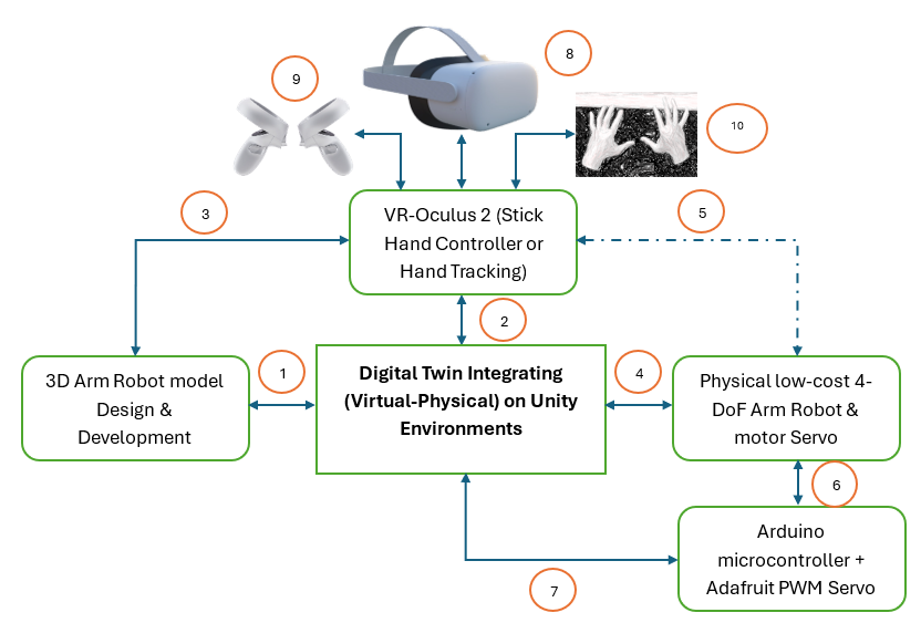
This framework proposes a configuration of low-cost components such as standard servo motors, an Arduino microcontroller, and a PWM driver [40]. The VR technology itself does not fall into the low-cost category, but it is used as an alternative immersive teleoperation technology in 3D space [40],[19]. As an integrated Unity and Oculus Quest 2 framework, it also demonstrates that VR technology can be directly utilized as a robot control interface in a feedback-less (open-loop) environment, making it relevant for preliminary testing, robotics education, and interactive simulation [26]. Figure 1 shows the RoboVR system integration framework, an implementation of the digital twin concept that links and combines parameters from the virtual and physical worlds (virtual–physical). In this case study, it integrates a virtual robot model in Unity with a low-cost physical robotic arm through VR technology control (Oculus Quest 2) [32].
The numbered items in Figure 1 are explained as follows: (1) The design and development of the 3D robot model are first carried out in Unity. This 3D model serves as a virtual representation that has a kinematic structure designed to be equivalent to the physical robot design [27]. (2) The virtual 3D model is then integrated into the Unity environment as the synchronization hub between the virtual and physical domains. Unity also acts as a bridge connecting Unity–VR and the VR input for control via stick hand controllers or hand-tracking [13]. (3) The virtual robotic arm manipulator environment and 3D objects are read and receive input from the Oculus Quest 2 VR device [19]. (4) Every user interaction in VR is translated into motion commands for the physical 4-DoF robotic arm driven by servo motors [7]. (5) The dashed line indicates that the low-cost robotic arm manipulator is not directly connected to the VR control device, but the VR control device can still move or control it directly because it has previously been connected through the bridge. (6) The motion command is forwarded to the Arduino + Adafruit PWM Servo Driver, which controls the servo rotation angles on the robot based on the instructions received from Unity via a serial protocol (UART/I²C) [12]. (7) The system sends control signals in the form of PWM values corresponding to the mapped angles from the virtual 3D model to the physical servos [8]. (8) The Oculus Quest 2 VR headset functions as an interactive–immersive display [9],[28][29], allowing users to visualize the robot’s position in 3D space in real time [1]. (9) If the input mode uses a stick controller, each button represents a discrete kinematic command (e.g., move joint +10° or –10°). (10) If the input mode uses hand-tracking, the VR’s internal cameras detect the user’s hand pose and convert it into kinematic commands. In the hand-tracking control mode, the user’s hand motion is mapped directly to the robot joint motion direction (gesture-based manipulation) with the same discrete kinematic parameters as the stick controller, interacting with the graphical ‘button-click’ interface [20].
This framework consists of three main layers: (i) the Unity simulation environment layer, which represents the 3D model of the robot and simultaneously functions as the control center; (ii) the serial communication layer (UART/I²C), which transmits instructions from Unity to the Arduino microcontroller and the PWM servo driver to actuate the physical system, and also connects to the VR device based on Oculus Quest 2 with a stick hand controller or hand-tracking to receive user input in the form of stick button clicks or gesture tracking clicks; and (iii) the physical 4-DoF robotic arm manipulator layer along with other hardware devices [13].
Figure 1. RoboVR Framework of Digital Twin integration system
Virtual Modeling and Unity Configuration Layer
The 3D robotic arm manipulator model structure is designed in the Unity environment as a (virtual) replica of its physical form. This model completes the DT concept as the component to be integrated with the physical design. Each part of the model object is identified with an embedded identity in the form of a separate control script written in C# and attached as a script object to each 3D object built in the Unity IDE. This script object is attached to detect interaction commands from the interface built as GUI buttons that trigger interaction or motion (kinematics), while simultaneously sending serial commands to the Arduino [17] to drive the servo motors’ kinematics on the physical robot [12].
Figure 2 shows the design of the 3D robotic arm manipulator model in the Unity environment. Figure 2(a) is the virtual 3D robot model constructed from five cube-shaped 3D primitives. Each object is manually designed and arranged proportionally so that it can represent the main components of the physical robot. Meanwhile, Figure 2(b) shows the hierarchical structure of the shape objects in Unity, where each shape model is a child of its parent shape. The hierarchy structure in Unity is a form of data (shape) organization in which this collection of shapes forms the robotic arm model object. When the base joint object is moved, all arm parts above it automatically move as well because of its position as the parent in the hierarchy. Conversely, rotation at the shoulder only affects the arm segment from the shoulder to the tip, without changing the base position. Meanwhile, movement at the elbow joint only affects the arm parts below it, namely the forearm segment and the wrist, so that the movement conforms to the physical structure of the robot. Thus, every movement applied to the parent object will automatically affect all of its child objects, in accordance with the transformation inheritance principle in Unity’s 3D hierarchy. Data in Table 1 presents the specification of the 3D model’s shape objects, including the direction of motion, axis of rotation, and angular movement range. These data parameters are used as the basis for constructing the script structure of each object in the virtual 3D robot model as a reference for control design.
Figure 2. Design of 3D Robotic arm manipulator Model in Unity environment, (a) Model build from scratch on Unity (b) Model build from scratch on Unity with shape object name and (c) Shape object hierarcy
Table 1. Object Specifications for a 4-DoF Robotic Arm in Unity form
Object Name | Movement Direction | Axis of Rotation / Motion | Angle Range | Primary Function |
Base | Left–Right rotation in the horizontal plane | Z-axis / Yaw | -90° to +90° | Adjusts robot's general orientation to the target |
Shoulder /Arm1 | Up–Down movement (vertical pitch motion) | Y-axis / Pitch | 0° to 90° | Controls height and global reach of the arm |
Elbow /Arm2 | Folding/Extending movement (up–down motion) | Y-axis / Pitch | 0° to 90° | Modifies the effective length of the arm |
Wrist + End Effector (claw) | Gripper movement | X-axis / Pitch | -90° to +90° | Aims the tool or gripper for manipulation |
Next, a script is created for the “Base” object as shown in Figure 3, where the script flow is presented in a flowchart. The stages in the flowchart start from initialization up to providing three functions that can later be called for kinematic motion synchronization with the physical object. First, the system initializes the parameters: the rotation step is set to 10°, the rotation axis used is the Y-axis, the motion limits are set between –90° and 90°, the current angle is set to 0°, and the initial base position is stored so it can be reused later. After the parameters are ready, there are three functions that use this setup. The RotateLeft() function will rotate the base to the left only if the current angle minus 10° is still greater than or equal to the lower limit (–90°); if this condition is met, the base rotates 10° to the left and the current angle is reduced by 10°. The RotateRight() function is the opposite: the base is rotated to the right only if the current angle plus 10° is still within the upper limit (≤ 90°); if allowed, the base rotates 10° to the right and the current angle is increased by 10°. The last function, ResetRotation(), returns the base to the initially stored physical position and also resets the current angle to 0°. The entire sequence in the flowchart ensures that the kinematic motion of the virtual 3D model of the “base” object remains within the design parameters set at the beginning, so that the base rotation stays within the –90° to 90° range, while still providing a reset function as a quick way to return it to the initial angle position.
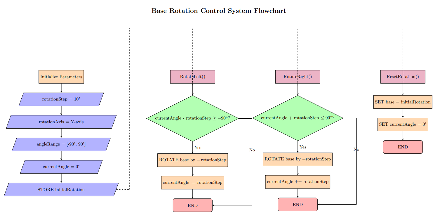
Figure 3. Flowchart ‘base’ object in Unity-C#
Communication Protocol, Interface Design, and Control Strategy Layer
The communication layer functions as middleware between the virtual simulation environment in Unity and the physical control unit based on Arduino Uno [10][11]. When the user interacts with the interface application (GUI button) previously built in Unity, every time a GUI button is pressed, the corresponding C# function is executed to generate a control instruction in the form of a text string. This instruction is sent via the serial communication protocol (UART) at a data transfer rate of 9600 bps through the USB port. The Arduino Uno, acting as the main controller, receives the data, parses the incoming command, and translates it into PWM control signals to set the rotation angle of the servo motor. Through this mechanism, every virtual action in Unity is directly mapped into motion on the 3D virtual robot model as well as on the physical robot [12],[38]. Script 1 is the essential pseudocode script illustrating how data communication between the Unity application (C#-based) and the Arduino Uno [13],[40] is carried out via a serial connection using a USB cable.
// Unity C#: send button commands to Arduino (115200, \n) using System.IO.Ports; using UnityEngine; public class RoboVRTx : MonoBehaviour { [SerializeField] string port = "COM3"; [SerializeField] int baud = 115200; SerialPort sp; void Start(){ sp = new SerialPort(port, baud){ NewLine="\n" }; try{ sp.Open(); Send("GET"); } catch { Debug.LogWarning("Serial open fail"); } } void OnDestroy(){ if(sp!=null && sp.IsOpen) sp.Close(); } void Send(string s){ if(sp!=null && sp.IsOpen) sp.WriteLine(s); } // Hook these to UI Button OnClick(): public void OpenClaw()=>Send("OPEN"); public void CloseClaw()=>Send("CLOSE"); public void BaseLeft()=>Send("LEFT"); public void BaseRight()=>Send("RIGHT"); public void ShoulderUp()=>Send("UPPER_VERTICAL_UP"); public void ShoulderDown()=>Send("UPPER_VERTICAL_DOWN"); public void ElbowUp()=>Send("TOP_VERTICAL_UP"); public void ElbowDown()=>Send("TOP_VERTICAL_DOWN"); public void ResetPose()=>Send("RESET"); public void GetStatus()=>Send("GET"); // Absolute example (call from InputField): SetBase(120) public void SetBase(int deg)=>Send($"SET_BASE:{deg}"); } |
As an explanation of the data communication pseudocode between the Unity C# model and the Arduino, this process involves opening the connection, reading and receiving requests from the Arduino, sending commands from Unity, and closing the connection. The program functions as a communication bridge between the Unity application and the Arduino hardware via the serial port. When the application is run, the system automatically opens a serial connection on COM3 at a baud rate of 9600 and starts a separate thread to continuously read data from the Arduino.
Next, the following is the pseudocode script 2 for serial communication [34] with the PWM driver on the Arduino side as a response to communication requests from Unity. The Arduino script acts as an interpreter that receives text-based commands via serial communication, processes them according to the motion logic, and then sets the servo motor position using the appropriate PWM signal. With this mechanism, every instruction triggered from the user interface in Unity—whether in the form of relative commands such as “LEFT” and “UPPER_VERTICAL_UP,” or absolute commands such as “SET_BASE:120”—will be mapped into physical motion on the 4-DoF robotic arm.
--pseudoceode Part 1--
Algorithm 1 — RoboVR Open-Loop Joint Control (Pseudocode)
Inputs: cmd ∈ {OPEN, CLOSE, LEFT, RIGHT, UPPER_VERTICAL_UP, UPPER_VERTICAL_DOWN, TOP_VERTICAL_UP, TOP_VERTICAL_DOWN, RESET, GET} ∪ {SET_<JOINT>:<θ>} State: angle[CLAW, BASE, UPPER, TOP] = [90, 90, 90, 110] minAngle = [45, 0, 0, 0] maxAngle = [90, 180, 180, 180] Parameters: Δ = {CLAW:5, BASE:10, UPPER:5, TOP:5} SERVO_FREQ = 60 Hz PWM(deg) = map(deg, 0..180 → 150..600)
Init: setup serial @115200, PCA9685 @SERVO_FREQ write all servos to angle[] print status INIT | --part 2--(continoued)
Procedure handle(cmd): if cmd == "RESET": angle ← [90, 90, 90, 110]; write all; print status; return if cmd == "GET": print status; return if cmd matches "SET_<JOINT>:<θ>": j ← JOINT; θ ← clamp(<θ>, minAngle[j], maxAngle[j]) angle[j] ← θ; write servo j; print status; return switch cmd: // relative commands case "OPEN": j←CLAW; δ←−Δ[CLAW] case "CLOSE": j←CLAW; δ←+Δ[CLAW] case "LEFT": j←BASE; δ←+Δ[BASE] case "RIGHT": j←BASE; δ←−Δ[BASE] case "UPPER_VERTICAL_UP": j←UPPER; δ←−Δ[UPPER] case "UPPER_VERTICAL_DOWN":j←UPPER; δ←+Δ[UPPER] case "TOP_VERTICAL_UP": j←TOP; δ←+Δ[TOP] case "TOP_VERTICAL_DOWN": j←TOP; δ←−Δ[TOP] default: print "ERR"; return
angle[j] ← clamp(angle[j] + δ, minAngle[j], maxAngle[j]) write servo j using PWM(angle[j]) print status OK |
In PWM-based servo control, the commanded angle is linearly converted to pulse width in the 150–600 range using the map() function on Arduino. For the base joint (0–180°), 0° is sent as PWM 150 and 180° as PWM 600, so 90° is around PWM 375. With the linear model in eq. (1):
| 
| (1) |
In the experiment, each GUI button click moves the DT object with a 10° increment. For the base joint, a 10° increment produces a change of about 25 PWM units. The servos on the shoulder, elbow, and wrist joints are limited to 90°, but still use the same PWM range, so 0° ≈ 150, 45° ≈ 300, and 90° ≈ 450; meaning each 10° on these joints adds roughly 33 units per click. This pattern allows the servo position to be controlled precisely from the given angle [27],[39]. From the dynamics side, servo motion generates torque related to the arm segment’s moment of inertia and its angular acceleration. From a dynamic perspective, torque arises due to ( ) the moment of inertia and (
 ) the angular acceleration, which can be modeled as eq. (2):
| 
| (2) |
In this open-loop system the torque is not controlled explicitly, but instead becomes a consequence of the motion. The model also assumes there is no feedback sensor, so the final servo position is assumed to follow the given PWM signal, and non-ideal factors such as friction, variable loads, or backlash are not yet included [8]. In the kinematic context, the end-effector position is calculated using forward kinematics [14] based on the joint angles in eq. (3):
| 
| (3) |
where ( ) and (
 ) are the end-effector coordinates,
  and
and  are the lengths of the first and second segments,
  is the angle at the shoulder joint, and
  is the angle at the elbow joint. The term (
 ) indicates that the orientation of the second segment depends on the orientation of the first segment [13].
Each time the GUI button is clicked, or is increased by 10°, then the ( ) position is recalculated. In the case study, if the shoulder is clicked 3 times and the elbow 2 times:
  ; which written in eq. (3) becomes: eq. (3)
  . In this way, the digital signal from the virtual environment can be traced all the way to the change in the physical end-effector position.
Interface design and Synchronized Physical-Virtual Kinematic Actions
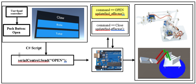
The interface design of the RoboVR framework serves as the main bridge between the user and the robot control system. Figure 4 explains the parts and communication process when, in a test scenario, pressing a GUI button in the application triggers a sequence of actions. The C# script attached to each virtual–physical robot object in Unity captures this input and sends the corresponding command to the Arduino via serial communication. On the PCA9685 port, the PWM channels on the module are mapped to the joint parts of the robot object. The rows of yellow–red pins on the driver act as PWM channels numbered “0”, “1”, “2”, “3”, and so on. Still in Figure 4, the first four channels are marked with a red box: Channel 0, connected to the base servo (base joint); Channel 1, connected to the shoulder servo; Channel 2, connected to the elbow servo; Channel 3, connected to the end-effector servo. Still in Figure 4, the Arduino microcontroller is connected to the PCA9685 and the power supply, and it is also connected via the serial port to the computer where the Unity system is installed.
| 
|
Figure 4. Mapping GUI Button Clicks to Physical and Virtual Kinematic Movements conneting with arduino and port driver channel to servo robot arm manipulator
Open-Loop Kinematic Control System
The open-loop system is the form of control implemented in the RoboVR framework. Every user action in the Unity VR environment generates a command in the form of a string (for example, “LEFT,” “UPPER_VERTICAL_UP,” “RESET”) which is sent to the Arduino Uno via serial communication. The Arduino then translates this command into a PWM (Pulse Width Modulation) signal to set the servo motor angle on each robot joint (base, shoulder, elbow, and wrist/end-effector) [13],[40]. Figure 5 illustrates the control flow in RoboVR that links user input in the virtual environment with the physical actuation of the robotic arm. The command source comes from the VR interface via hand controller or stick controller. The Arduino acts as the controller  , which receives and processes the instruction command, and produces the appropriate PWM signal to drive the servo actuators on each robot joint. The physical response of the robotic arm is represented by the joint kinematics block
  , which determines the output angles
  according to the received commands. As an open-loop control process, motion accuracy fully depends on the consistency between the virtual model and the physical realization [35].
As shown in Figure 5, we approach it with the following explanation. Figure 6 focuses on the stages of control-signal transformation that occur at the microcontroller and actuator levels. The process begins with the input given through the GUI interface, which is then mapped into a commanded angle  , i.e., the target angle to be achieved by each robot joint. This value is not sent directly to the actuator; instead, it is first converted into a PWM signal, because the servo motor responds only to pulse width in microseconds, not to degree values. The Arduino microcontroller acts as the interpreter that converts the angle instruction into a PWM signal that matches the servo’s characteristics [12]. After the signal is sent, the internal dynamics of the servo—including its internal controller, torque, response speed, and mechanical limitations determine the final output angle
  .
.
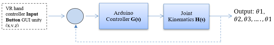
Figure 5. Robotic Arm VR Controller handling

Figure 6. Servo motor handling
Figure 6 explains that the angle is controlled by the GUI-button “click” input in eq. (4) (discretized input):
| 
| (4) |
where  is the initial angle;
  is the number of button clicks; and
  is the angle increment for each click. This incremental
  model in eq. (4) is based on the standard stepwise control logic commonly used in joint-space manipulation [13]. The following eq. (5) is used for converting the angle to PWM:
| 
| (5) |
with  , this equation ensures a consistent mapping between the PWM signal and the servo angle. For the open-loop approach, it is assumed that the servo responds ideally to the PWM signal:
| 
| (6) |
Eq. (6) represents the basic assumption of an open-loop control system, in which the actual angle  of the servo motor at time
  is considered equal to the commanded angle sent by the control system.
VR Controller
The VR controller includes the stick controller and the hand-tracking controller. Both of these control handles are native to the device. In the specific configuration for hand-tracking, the VR headset uses inside-out cameras and computer vision algorithms to directly detect the user’s hand position and orientation without a physical controller, enabling natural interaction in 3D space with the physical robot arm [18][19]. In the Unity integration, the configuration is carried out by activating the XR Hands module or the Meta XR SDK, so that every hand movement can be translated into a virtual object animation synchronized with the user’s workspace [20]. Figure 7 shows the documentation of a user testing the VR device to run a test scenario on the servo robot object. When wearing the headset, the displayed view is the 3D model of the robot object and Figure 8. The user tests the movement of the virtual robot by running the GUI-button application and clicking the buttons (see Figure 8). The initial validation carried out is to observe whether the kinematic motion of the virtual robot has followed the design that was previously defined.
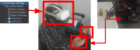
Figure 7. VR headset hand controller physical robot arm
Physical System Design Layer (Actuation Layer)
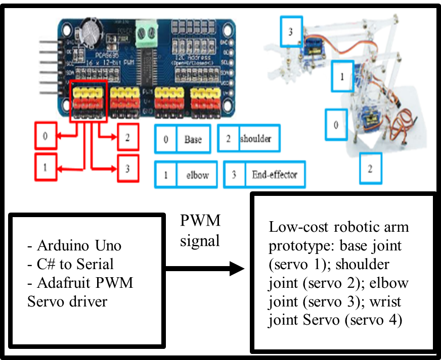
This section explains the theoretical design of angle variation that is converted into PWM by the Arduino. As mentioned in the previous subsection, the main components of this system consist of four low-cost SG-90 micro servo motors; unlike the MG996R, which has higher torque, the SG-90 micro servos were selected because the torque requirements of the low-cost 4-DoF robotic arm are already met and suitable for its dynamic aspects [40]. For the physical construction, the robotic arm used is a low-cost educational robot that is also commonly found on online marketplaces. This type of low-cost educational robot is often used to bridge theoretical kinematics and practical implementation. The arm is made of lightweight acrylic material, with a forward kinematics reach distance of about 22 cm, and the load between each link section is less than 2 gm. Table 2 presents the servo device specifications and the theoretical design of the angle–PWM mapping. Link parameters are not included in the table because the study is still focused on the kinematic operation of each joint object of the virtual and physical robot.
Table 2 serves as a summary of how many PWM counts per degree are used in the integration. The Table 2 explains the configuration of each servo used in the robotic arm, starting from the PWM channel used to its kinematic function. Servo 1 on PWM channel 0 is assigned to drive the base joint with the widest angle range, 0–180°, because this part is the main rotation axis of the arm. Servos 2, 3, and 4 are on channels 1, 2, and 3 respectively, and all of them operate in the 0–90° range because they move the “finer” joints (shoulder, elbow, and wrist). All four use SG90 micro servos with torque of around 1.8 kg·cm (±0.176 N·m), so the angle-to-PWM mapping can be standardized using the formula PWM = 150 + 2.5 × θ, except that for joints limited to 90° the formula is applied only up to θ = 90°. The last column explains the kinematic role: the base for the main rotation, the shoulder for moving the lower vertical arm, the elbow for moving the upper vertical arm, and the wrist for moving the wrist or end-effector.
Table 2. Servo specification and PWM-to-angle mapping for the robot arm joints
Joint / Servo | PWM Channel | Controlled Joint | Angle Range | Torque (SG90) | PWM mapping (deg → count) |
Servo 1 | 0 | Base joint | 0–180° | ≈ 1.8 kg·cm (≈ 0.176 N·m) | PWM = 150 + 2.5 × θ |
Servo 2 | 1 | Shoulder joint | 0–90° | ≈ 1.8 kg·cm (≈ 0.176 N·m) | PWM = 150 + 2.5 × θ (θ ≤ 90°) |
Servo 3 | 2 | Elbow joint | 0–90° | ≈ 1.8 kg·cm (≈ 0.176 N·m) | PWM = 150 + 2.5 × θ (θ ≤ 90°) |
Servo 4 | 3 | Wrist joint | 0–90° | ≈ 1.8 kg·cm (≈ 0.176 N·m) | PWM = 150 + 2.5 × θ (θ ≤ 90°) |
Note:  = angle in degrees; the value 2.5 is obtained from (600 – 150) / 180; for servos that are used only up to 90°, the same formula is applied but is limited to 90; every 1° angle change in Arduino should change the PWM value sent to the PCA9685 by about 2.5 counts.
RESULT AND DISCUSSION
The RoboVR system prototype was successfully developed as an integration framework between the virtual model in Unity and the physical 4-DoF robotic arm based on an Arduino Uno microcontroller. The 3D virtual model was designed using basic cube and cylinder shapes to represent each joint: base, shoulder, elbow, and end-effector. The object hierarchy in Unity was organized in a parent–child structure, so that every movement of a parent joint (for example, the base) automatically affected its child joints and produced motion consistent with robotic kinematics principles. The graphical interface consisted of five main control buttons—four for moving each joint and one reset button. In addition, the system was controlled via the Oculus Quest 2 VR controller. Each user interaction triggered a C# function in Unity that sent a string-based command to the Arduino through the serial port. The Arduino then translated the command into PWM signals via the PCA9685 driver to drive the SG/MG90S servos on each joint.
GUI-button Click Application in Unity and Testing
A GUI-button application was built consisting of five main buttons: four buttons were used to control the motion of each joint individually, while one button functioned as a reset button to return all joint angles to the initial (default) position. In Figure 8, when the “Rotate Left” button is pressed via the VR hand controller, the RotateLeft() function is executed to rotate the base joint, while simultaneously sending the string "LEFT" to the Arduino. Thus, the virtual object and the physical robot move simultaneously in a synchronized manner. All parts of the 3D model are arranged in a single structured hierarchy, so that motion in one component, such as the arm, automatically affects the position of the other components, including the end-effector. Testing was carried out by pressing the GUI-button clicks, both individually and sequentially, to observe whether the kinematic motion of the 3D model was correctly synchronized with the kinematics of the virtual and physical robot at the corresponding angles. The results showed that the communication system worked properly and as intended.
Figure 9 presents a series of tests on the physical robot and the 3D virtual model from various angles, along with the control interface. Subfigures (a) and (b) show top views of the physical and virtual systems that are aligned, confirming consistency in orientation and workspace reach. Subfigures (c) and (d) display rear views in both domains, helping to validate the mapping of the shoulder–elbow–wrist joints. Subfigures (e) and (f) show consistent right-side views, illustrating planar rotation at the base and visual changes in the joint angles. Subfigure (g) shows the computer–virtual setup connected to the physical robot, depicting the command and feedback flow during testing. Subfigure (h) displays the virtual control buttons—i.e., the VR/Unity button interface that triggers motion commands to the microcontroller to drive the servos on the real robot.
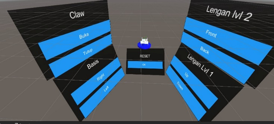
Figure 8. GUI button Interface for VR joystick or Hand Tracking controller
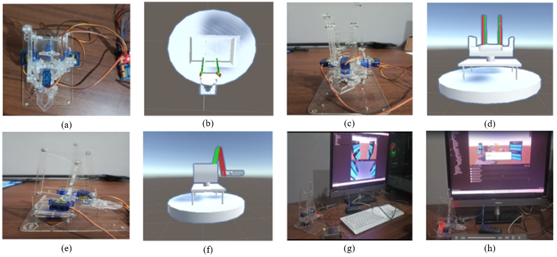
Figure 9. (a) physical top view, (b) 3d virtual top view), (c) physical back view, (d) 3d virtual back view, (e) physical right view, (f) 3d virtual right view, (g) computer-virtual with physical, (h) side-front virtual controller button view
Mean Absolute Error (MAE)
The testing was carried out by pressing the GUI button/VR controller for each joint (base, shoulder, elbow) and recording two things: (i) the MAE, namely the absolute difference between the Unity command angle and the physical servo angle at each click, calculated using eq. (6). The data were collected repeatedly for each joint to identify which motions were linear (base, elbow) and which were affected by mechanical factors (shoulder); and (ii) the latency, namely the time interval from the command click in Unity until the servo started to move (observed separately using a timer). MAE measurement in the RoboVR testing was intended to evaluate the accuracy of kinematic integration between the virtual and physical domains, as well as to measure motion synchronization in the digital twin–VR-based open-loop control system. It should be noted that the servo joint angle error was still measured conventionally using a ruler and a square, so there is a possibility of small observational errors in the angle data.
| 
| (7) |
where:  = total number of observations;
  = actual value from the physical robot;
  = value from the virtual simulation [15].
Table 3 shows the measurement results and comparison of kinematic angles between the physical and virtual robot arm based on the MAE value. The Base-Right and Base-Left joints show synchronized rotation with MAE of 0.05 and 0.02 respectively, while the shoulder and elbow joints show slight deviations due to differences in servo response, with MAE of 0.03–0.11. The end-effector shows full correspondence with MAE = 0. It should be noted that during construction/installation of the end-effector section, the servo performance appeared to be quite good. Overall, the digital twin–VR system demonstrates strong spatial and temporal synchronization accuracy between the virtual and physical models. The average response time from button press to servo movement ranges from 0.4 to 0.6 seconds, depending on the command string length and the execution speed on the Arduino side can be seen in Figure 10.
Table 3. MAE final result for the comparison of angular kinematic displacements physical-virtual
Joint |  (°) (°)
|  (°) (°)
| MAE |
Base-Right | 57 | 60 | 0.05 |
Base-Left | 39 | 40 | 0.02 |
Shoulder-Up | 29 | 30 | 0.03 |
Shoulder-Down | 9 | 10 | 0.11 |
Elbow-Up | 28 | 30 | 0.07 |
Elbow-Down | 9 | 10 | 0.11 |
End-effector Open | 45 | 45 | 0 |
End-effector Close | 45 | 45 | 0 |
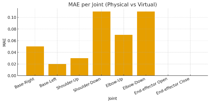
Figure 10. Comparison of angular kinematic displacements between physical and virtual robotic arms
Table 4 presents a comparison between the virtual angles (commanded from Unity/VR) and the measured physical servo angles for each controller button click, separated by joint and direction of motion. The first and second rows show the base joint to the right and to the left: each click increases or decreases the virtual angle by 10°, and the value next to it is the angle actually achieved by the servo; it can be seen that up to the 2nd click the servo value is exactly the same, but starting from the 3rd click a small difference of 1–3° appears, which becomes more noticeable near the end of the range. The next rows are for the shoulder moving up and down; here the virtual angle increases by 20° (or decreases by 20°) per click, but the servo only moves about 9–19°, indicating a scaling factor between the command and the actual motion. The last rows are for the elbow down movement, which shows the cleanest pattern because the servo angle almost follows the virtual angle at every click, only slightly smaller. This table briefly shows how each joint responds to angle commands of the same magnitude, and where the deviations occur between the expected angle and the physical angle achieved.
For Figure 11, it is a combination of six pairs of curves, each representing a comparison between the commanded angle from Unity and the actual angle achieved by the servo for each joint. The curves are grouped in the legend according to their joints to make them easier to read. In the Base joint group (legend in the upper left), there are two pairs of lines: “Base-right (Unity)” is drawn with a blue line with circle markers and compared with “Base-right (Servo)” in orange with square markers; then “Base-left (Unity)” is in green with circle markers and compared with “Base-left (Servo)” in red with square markers. The colors and markers in each pair indicate that the two lines are being compared: the one labeled Unity (circle) is the ideal target angle sent from the virtual environment, while the one labeled Servo (square) is the actual angle obtained from physical measurement. The visual gap between the two lines shows the rotation error on the base. Still in Figure 11, the second group in the legend, the Shoulder joint (bottom left), consists of “Shoulder-up (Unity)” in purple with circle markers compared to “Shoulder-up (Servo)” in brown with square markers, and “Shoulder-down (Unity)” in pink with circle markers compared to “Shoulder-down (Servo)” in gray with square markers. In this part, it can be seen that the servo lines are always closer to the horizontal axis than the Unity lines, meaning the achieved angles are smaller than the commanded ones; this indicates mechanical resistance/friction in the shoulder. The last group in the legend, the Elbow joint (bottom right), contains “Elbow-down (Unity)” in olive/yellowish-green with circle markers and “Elbow-down (Servo)” in cyan/light blue with square markers. These two lines almost overlap, so the comparison shows that the elbow is the joint whose angular response most closely follows the Unity command.
Table 4. Joint-wise virtual vs measured angle per controller click
Joint | Direction | Comparison per-times button 'click' - Degree (click/degree) |
0 | 1 | 2 | 3 | 4 | 5 | 6 | 7 | 8 | 9 |
base | right | 0 / 0° | 10 / 10° | 20 / 20° | 30 / 29° | 40 / 39° | 50 / 48° | 60 / 57° | 70 / 67° | 80 / 77° | 90 / 87° |
base | left | 0 / 0° | -10 / -10° | -20 /-20° | -30 /-29° | -40 / -39° | -50 /-48° | -60 / -57° | -70 /-67° | -80 /-76° | -90 /-86° |
shoulder | up | 0 / 0° | 20 / 9° | 40 / 19° | – | – | – | – | – | – | – |
shoulder | down | 0 / 0° | -20 / -9° | -40 /-19° | -60 /-28° | -80 / -38° | -100/-47° | – | – | – | – |
elbow | down | 0 / 0° | -10 / -9° | -20 /-19° | -30 /-28° | -40 / -39° | -50 /-48° | -60 / -57° | – | – | – |
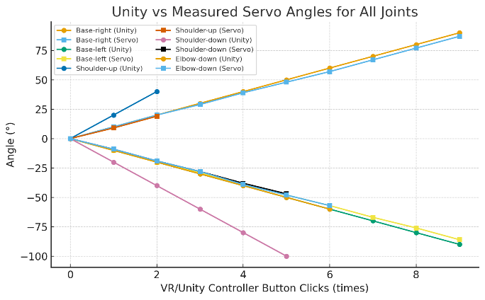
Figure 11. Unity vs measyred servo angles for all joints
Analysis of Motion Parameters per Joint
Table 5 summarizes the quality of the relationship between the commanded angle in Unity and the actual servo angle achieved for each joint. The “Number of data points (n)” column shows how many samples/clicks were taken per joint. The “Unity range” column indicates the angle span tested in Unity for example, base-right from 0 to 90°, while base-left from 0 to –90°. The “Initial conversion factor” represents the estimated initial Unity-to-servo scaling from the first step; for the base right/left the value is ≈1, meaning 10° in Unity becomes approximately 10° on the servo, whereas for the shoulder the value is ≈0.47 because 20° in Unity becomes only about 9° on the servo. “Average deviation” and “Maximum deviation” indicate how far the servo drifts from the Unity angle, on average only 1–2° and at most 3–4° on the base and 2° on the shoulder and elbow. The last column, “Linearity note,” marks that all joints are essentially linear (their angle changes are proportional to the command), with only a slight drop/increase at the ends of the range for the base. This Table 5 shows that the calibration is already good and the deviations are still within a small margin, with a clear conversion factor for each joint.
Table 5. Summary of Unity–servo angle mapping accuracy per joint
Joint | Direction | Number of data ‘click’(n) | Unity range | Initial conversion factor* | Average deviation** | Maximum deviation | Linearity note |
base | right | 10 | 0 … 90 | ≈ 1.00 (10 → 10) | 1–2° smaller | 3° | Linear, drops at the end |
base | left | 10 | 0 … –90 | ≈ 1.00 (–10 → –10) | 1–2° larger | 4° | Linear, rises at the end |
shoulder | up | 3 | 0 … 40 | ≈ 0.47 (20 → 9) | < 1° | 1° | Linear |
shoulder | down | 6 | 0 … –100 | ≈ 0.47 (–20 → –9) | 1–2° | 2° | Linear |
elbow | down | 7 | 0 … –60 | ≈ 0.96 (–10 → –9) | 1–2° | 2° | Linear |
* Initial conversion factor = rough Unity → servo scaling from the first step.; ** Average deviation = typical difference between Unity angle and physical servo angle.
Statistical Analysis of Angle Mapping
Table 6 describes how large the difference (error) is between the angle commanded in Unity and the angle actually achieved by the servo for each type of motion (joint/motion). The “Error calculated” column shows the sequence of differences computed as servo–Unity for each measurement point. From that sequence, two statistical parameters are then calculated: the mean error and the standard deviation (std dev). For the base–right motion, the mean error is –1.60° with a std dev of 1.35°, meaning the servo tends to move slightly less than the Unity angle (negative) and the error spread is small and consistent. Base–left is the opposite: the mean error is 1.8° and the std dev is 1.62°, so the servo tends to move slightly more than the command and the variation is still small. For shoulder–up and especially shoulder–down, the mean error values are much larger (–10.67° and 26.5°) and the std dev is also large; this indicates that on the shoulder joint there is a dynamic issue in the shoulder design. Friction between shoulder parts causes the servo torque not to be fully transmitted so the servo angle achieved is smaller than the commanded angle. The error here reflects mechanical limitations (friction and load) rather than an error in angle mapping, and this becomes an important note and finding in this study. Meanwhile, elbow–down has a mean error of 1.43° and a std dev of only 0.98°, so it can be said that the elbow motion is the most consistent in following the command. This Table 6 provides an overview of which joints are almost 1:1 with Unity (base and elbow) and which ones clearly operate with a different scale (shoulder).
Table 6. Summary of Unity–servo angle errors by joint/motion
Joint / Motion | Error calculated | Mean error (°) | Std dev error (°) |
base – right | servo – Unity (0, 0, 0, –1, –1, –2, –3, –3, –3, –3) | –1.60 | 1.35 |
base – left | servo – Unity (0, 0, 0, +1, +1, +2, +3, +3, +4, +4) | 1.8 | 1.62 |
shoulder – up | servo – Unity (0, –11, –21) | –10.67 | 10.5 |
shoulder – down | servo – Unity (0, 11, 21, 32, 42, 53) | 26.5 | 19.73 |
elbow – down | servo – Unity (0, 1, 1, 2, 1, 2, 3) | 1.43 | 0.98 |
This study shows that the main gap in open-loop control schemes namely the absence of sensor feedback and the potential virtual–physical motion mismatch can be narrowed using a DT–VR integration framework that is lightweight in hardware and already implemented. The proposed framework unifies three main layers: (1) a Unity-based 3D virtual environment as the digital twin that serves as the source of kinematic commands, (2) a translation/mapping layer that converts Unity angles into standardized PWM signals, and (3) a physical execution layer based on Arduino, PWM module (PCA9685), micro servos that realizes the motion on the 4-DoF robotic arm. Through this pipeline, user actions in VR (joystick / hand-tracking) can directly appear on the physical robot even though the system remains open-loop. Its key contribution is the demonstration that DT–VR integration does not always have to rely on expensive robotic platforms and closed-loop systems: with the Unity–servo calibration already presented in Table 6 and comparative plots, the system is able to maintain motion alignment on most joints, while the deviation on the shoulder can be identified as a dynamic constraint specific to its mechanism. The novelty of this research lies in applying DT–VR for low-cost teleoperation in open-loop mode while also providing calibration artifacts that can be directly reused or extended in subsequent studies.
Limitation and Future Work
This study still has limitations, such as the mechanical aspect of the shoulder section needing to be reviewed so that friction and load on the servo can be reduced. In addition, the difference in kinematic angle magnitude between the virtual model and the servo should be addressed in future improvements, making joint torque selection an option for the solution. Furthermore, the current open-loop control system and manual measurement process limit the precision and real-time adaptability of motion synchronization between the virtual and physical domains. Future research will focus on developing a closed-loop feedback control system with integrated sensors to enhance positional accuracy and stability.
CONCLUSIONS
This study produced a DT–VR integration framework capable of sending kinematic commands via serial communication across ports from Unity to a low-cost physical 4-DoF robotic arm based on Arduino–PCA9685–servo in a measurable manner under open-loop mode on a low-cost platform. VR control commands—whether through the stick controller or hand-tracking to Unity via the XR SDK plugin—were also validated. The virtual–physical integration measurements further showed that kinematic synchronization of virtual–physical angles with a latency of 0.4 to 0.6 seconds occurred best on the end-effector and the base joint, both to the right and to the left: every 10° increment in Unity was followed by the servo with only a small difference, with MAE of about 0.05 on the base-right and 0.02 on the base-left. Deviations began to appear after the 3rd button click and became larger near the end of the range, but were still in the 1–3° or at most 3–4° range, so linearity was maintained. The shoulder and elbow also followed a linear pattern, but the shoulder moved less than the 20° command in Unity, achieving only about 9–19° on the physical servo. This is reflected in the larger error on shoulder-up/down and is an important finding showing that the limitation does not lie in the PWM mapping, but in the mechanical dynamics. The elbow had the cleanest response with MAE of 0.03–0.11 and low standard deviation, while the end-effector showed full agreement with MAE = 0. The calibration data used as validation were presented in the form of tables and plots, showing the kinematic phenomena resulting from the integration between the virtual model and the physical system. This visualization shows the motion response at each joint, where some of them were identified as weak points in the kinematic structure. The framework has been equipped with calibration artifacts so that the angle deviation of each joint can be identified. This study provides guidance for building integration and validation of the integration as the next direction.
Acknowledgement
The authors would like to thank the experimental assistant team, the data collection team, and the equipment support at the Computer Engineering laboratories of Universitas Mataram and Universitas Negeri Malang.
Conflicts of Interest
The authors declare no conflict of interest.
REFERENCES
- T. Luu et al., “Enhancing real-time robot teleoperation with immersive virtual reality in industrial IoT networks,” International Journal of Advanced Manufacturing Technology, vol. 139, pp. 6233–6257, 2025, https://doi.org/10.1007/s00170-025-16236-w.
- F. Nenna et al., “The virtualization of human–robot interactions: a user-centric workload assessment,” Virtual Reality, vol. 27, pp. 553–571, 2023, https://doi.org/10.1007/s10055-022-00667-x.
- J. Audonnet, F. Bénard, and C. Marchand, “IMMERTWIN: An immersive digital twin framework for robotic teleoperation,” in Proc. IEEE Int. Conf. on Virtual Reality and Augmented Reality (VRAR), pp. 101–110, 2024, https://doi.org/10.48550/arXiv.2409.08964.
- F. P. Audonnet, J. Grizou, A. Hamilton, and G. Aragon-Camarasa, “TELESIM: A modular and plug-and-play framework for robotic arm teleoperation using a digital twin,” in Proc. 2024 IEEE Int. Conf. on Robotics and Automation (ICRA), pp. 17770–17777, 2024, https://doi.org/10.1109/ICRA57147.2024.10610935.
- J. S. Artal-Sevil, A. Acón, J. L. Montañés, and J. A. Domínguez, “Design of a low-cost robotic arm controlled by surface EMG sensors,” in Proc. 2018 XIII Technologies Applied to Electronics Teaching Conf. (TAEE), pp. 1–8, 2018, https://doi.org/10.1109/TAEE.2018.8476126.
- E. Iadanza et al., “A robotic arm for safe and accurate control of biomedical equipment during COVID-19,” Health Technology, vol. 13, pp. 285–300, 2023, https://doi.org/10.1007/s12553-022-00715-1.
- H. M. Ali, Y. Hashim, and G. A. Al-Sakkal, “Design and implementation of Arduino based robotic arm,” International Journal of Electrical and Computer Engineering (IJECE), vol. 12, no. 2, pp. 1411–1418, 2022, https://doi.org/10.11591/ijece.v12i2.pp1411-1418.
- S. Otto and R. Seifried, “Open-loop control of underactuated mechanical systems using servo-constraints: analysis and some examples,” in Lecture Notes in Applied and Computational Mechanics, pp. 81–122, 2018, https://doi.org/10.1007/11221_2018_4.
- D. Bui, W. Li, and H. Huang, “CarGameAR: An integrated AR car game authoring interface for custom built car programed on Arduino board,” In Proceedings of the 2023 7th International Conference on Graphics and Signal Processing, pp. 62-66, 2023, https://doi.org/10.48550/arXiv.2305.00084.
- P. Badoniya and J. George, “Two link planar robot manipulator mechanism analysis with MATLAB,” International Journal for Research in Applied Science & Engineering Technology (IJRASET), vol. 6, no. 7, 2018, https://doi.org/10.22214/ijraset.2018.7132.
- T. O. Hodson, “Root-mean-square error (RMSE) or mean absolute error (MAE): when to use them or not,” Geoscientific Model Development, vol. 15, pp. 5481–5487, 2022, https://doi.org/10.5194/gmd-15-5481-2022.
- N. Dunbar. Arduino Language Reference. in Arduino Software Internals. Berkeley, CA: Apress, 2020, https://doi.org/10.1007/978-1-4842-5790-6_3.
- E. Kučera, O. Haffner, and Š. Kozák, “Connection between 3D engine Unity and microcontroller Arduino: a virtual smart house,” in 2018 Cybernetics & Informatics (K&I), pp. 1–8, 2018, https://doi.org/10.1109/CYBERI.2018.8337531.
- M. Muladi, S. Sendari, and I. A. E. Zaini, “Colour-based object sorting in a wide range and dense target points using arm robot,” in Proc. 2nd Int. Conf. Vocational Education and Training (ICOVET 2018), pp. 132–138, 2019, https://doi.org/10.2991/icovet-18.2019.33.
- A. Mazumder, et al., “Towards next generation digital twin in robotics: trends, scopes, challenges, and future,” Heliyon, vol. 9, no. 2, p. e13359, 2023, https://doi.org/10.1016/j.heliyon.2023.e13359.
- E. Zio and L. Miqueles, “Digital twins in safety analysis, risk assessment and emergency management,” Reliability Engineering & System Safety, vol. 246, p. 110040, 2024, https://doi.org/10.1016/j.ress.2024.110040.
- J. K. Touckia, “Integrating the digital twin concept into the evaluation of reconfigurable manufacturing systems (RMS): literature review and research trend,” International Journal of Advanced Manufacturing Technology, vol. 126, pp. 875–889, 2023, https://doi.org/10.1007/s00170-023-10902-7.
- G. Buckingham, et al., “Hand tracking for immersive virtual reality: opportunities and challenges,” Frontiers in Virtual Reality, vol. 2, 2021, https://doi.org/10.3389/frvir.2021.728461.
- L. Guo, Z. Lu and L. Yao, "Human-Machine Interaction Sensing Technology Based on Hand Gesture Recognition: A Review," in IEEE Transactions on Human-Machine Systems, vol. 51, no. 4, pp. 300-309, 2021, https://doi.org/10.1109/THMS.2021.3086003.
- D. Borzelli, et al., “A quantitative assessment of the hand kinematic features using Oculus Quest 2,” Scientific Reports, vol. 15, no. 1, p. 8842, 2025, https://doi.org/10.1038/s41598-025-91552-5.
- D. J. Wagg, C. Burr, J. Shepherd, Z. Xuereb Conti, M. Enzer, and S. Niederer, “The philosophical foundations of digital twinning,” Data-Centric Engineering, vol. 6, 2025, https://doi.org/10.1017/dce.2025.4.
- T. C. Callari, R. Vecellio Segate, E. M. Hubbard, A. Daly, and N. Lohse, “An ethical framework for human–robot collaboration for the future people-centric manufacturing,” Technology in Society, vol. 78, 102680, 2024, https://doi.org/10.1016/j.techsoc.2024.102680.
- R. Etemad-Sajadi, A. Soussan, and T. Schöpfer, “How ethical issues raised by human–robot interaction influence intention to use,” International Journal of Social Robotics, vol. 14, no. 4, pp. 1103-1115, 2022, https://doi.org/10.1007/s12369-021-00857-8.
- H. C. Ukwuoma, G. Dusserre, G. Coatrieux, and J. Vincent, “Analysis of digital twin and its physical object: exploring the efficiency and accuracy of datasets for real-world application,” Data Science and Management, vol. 7, no. 4, pp. 361–375, 2024, https://doi.org/10.1016/j.dsm.2024.04.002.
- M. Sakhineti and S. Jayabalan, “Design and fabrication of SHRALA: social humanoid robot based on autonomous learning algorithm,” Procedia Computer Science, vol. 171, pp. 2050–2056, 2020, https://doi.org/10.1016/j.procs.2020.04.220.
- M. Eslami, M. Pirmoradian, A. Mokhtarian, and S. Baghaei, “Design and manufacture of a soft robot with dual-interaction in virtual reality,” Heliyon, vol. 9, no. 9, p. e19997, 2023, https://doi.org/10.1016/j.heliyon.2023.e19997.
- P. V. F. Zawadniak, L. Piardi, T. Brito, et al., “Micromouse 3D simulator with dynamics capability: a Unity environment approach,” SN Applied Sciences, vol. 3, p. 259, 2021, https://doi.org/10.1007/s42452-021-04239-7.
- B. Estrany, C. Marin, M. Mascaró, et al., “Multimodal human–machine interface devices in the cloud,” Journal on Multimodal User Interfaces, vol. 12, pp. 125–143, 2018, https://doi.org/10.1007/s12193-017-0253-z.
- F. D. Von Borstel, M. S. Haro, J. F. Villa-Medina, et al., “Propulsive element normal force based on acceleration measurements experienced by a subcarangiform robotic fish,” Journal of Intelligent & Robotic Systems, vol. 104, p. 73, 2022, https://doi.org/10.1007/s10846-022-01600-9.
- G. W. Wiriasto, R. Misbahuddin, A. S. Rachman, I. L. Harahap, L. S. I. Akbar, M. S. Iqbal, and M. Fikriansyah, “Study on the development of a virtual reality application for skeletal anatomy learning using rapid application development (RAD),” Jurnal Penelitian Pendidikan IPA, vol. 10, no. 8, pp. 5726–5733, 2024, https://doi.org/10.29303/jppipa.v10i8.8722.
- L. Clark, M. E. Iskandarani, and S. Riggs, “Reaching interactions in virtual reality: the effect of movement direction, hand dominance, and hemispace on the kinematic properties of inward and outward reaches,” Virtual Reality, vol. 28, p. 43, 2024, https://doi.org/10.1007/s10055-023-00930-9.
- H. Abe et al., “Combining AR and input device to control remotely a robot arm,” Human-Intelligent Systems Integration, pp. 1-14, 2025, https://doi.org/10.1007/s42454-025-00076-w.
- G. Maculotti et al., “Traceable digital twin for accurate positioning of industrial robot arms in human–robot collaborative systems,” Flexible Services and Manufacturing Journal, pp. 1-37, 2025, https://doi.org/10.1007/s10696-025-09632-7.
- R. F. Pitzalis et al., “Application of augmented reality-based digital twin approaches: a case study to industrial equipment,” International Journal of Advanced Manufacturing Technology, vol. 138, pp. 3747–3763, 2025, https://doi.org/10.1007/s00170-025-15755-w.
- I. D. Ortiz and O. A. Vivas, “Virtual reality platform for Cartesian manipulation of digital twin in a UR3 robot,” Ingeniería y Competitividad, vol. 27, no. 1, 2025, https://doi.org/10.25100/iyc.v27i1.14418.
- Y. Cen, J. Deng, Y. Chen, H. Liu, Z. Zhong, B. Fan, L. Chang, and L. Jiang, “Digital twin-empowered robotic arm control: an integrated PPO and fuzzy PID approach,” Mathematics, vol. 13, no. 2, p. 216, 2025, https://doi.org/10.3390/math13020216.
- A. K. Ali, “A comprehensive framework for integrating robotics and digital twins in façade perforation,” ARO, vol. 12, no. 1, pp. 191–202, 2024, https://doi.org/10.14500/aro.11351.
- F. Mo et al., “Digital twin-based self-learning decision-making framework for industrial robots in manufacturing,” International Journal of Advanced Manufacturing Technology, vol. 139, pp. 221–240, 2025, https://doi.org/10.1007/s00170-025-15844-w.
- J.-S. Shaw and Y.-H. Huang, “Virtual modeling of an industrial robotic arm for energy consumption estimation,” Advances in Technology and Innovation, vol. 8, no. 4, pp. 267–277, 2023, https://doi.org/10.46604/aiti.2023.11957.
- P. Chotikunnan, et al., “Enhancing MG996R servo motor performance using PSO-tuned PID and feedforward control,” International Journal of Robotics and Control Systems, vol. 5, no. 2, pp. 1120–1138, 2025, https://doi.org/10.31763/ijrcs.v5i2.1854.
- D. Sun, A. Kiselev, Q. Liao, T. Stoyanov, and A. Loutfi, “A new mixed-reality-based teleoperation system for telepresence and maneuverability enhancement,” IEEE Transactions on Human-Machine Systems, vol. 50, no. 1, pp. 55–67, 2020, https://doi.org/10.1109/THMS.2019.2960676.
AUTHOR BIOGRAPHY
Giri Wahyu Wiriasto is a graduate student in the Electrical Engineering and Informatics department at Universitas Negeri Malang, Indonesia. His research interests include robotics trajectory planning, reinforcement learning, and the integration of physical–virtual environments using VR technology. Contact: giri.wahyu.2505349@students.um.ac.id; ORCID: https://orcid.org/0000-0002-6832-0815. |
|
Siti Sendari is a senior researcher in the Electrical Engineering and Informatics department at Universitas Negeri Malang, Indonesia. Her research interests include reinforcement learning, robotics, and human–computer interaction (HCI). Contact: siti.sendari.ft@um.ac.id ORCID: https://orcid.org/0000-0002-8681-7024. |
|
Dyah Lestari is a researcher in the Electrical Engineering and Informatics department at Universitas Negeri Malang, Indonesia. Her research interests include robotics, digital image processing, and computational intelligence. Contact: dyah.lestari.ft@um.ac.id ORCID: https://orcid.org/0000-0002-8488-5146. |
|
Muhamad Syamsu Iqbal is a senior researcher in the Electrical Engineering department at Universitas Mataram, Indonesia. His research interests include Wireless Sensor Networks (WSN) and Intelligent Communication Systems. Contact: msiqbal@unram.ac.id ORCID: https://orcid.org/0000-0002-1436-2745. |
|
Norrima Mochtar is an accomplished academic and researcher in Electrical Engineering, specializing in Artificial Intelligence (AI) and Robotics. She earned her Bachelor of Engineering (B.Eng.) in Electrical Engineering from the University of Malaya in 2000. In 2002, she was awarded the prestigious Panasonic Scholarship after a rigorous national selection process, allowing her to pursue a Master of Engineering in Oita, Japan, which she completed in 2006. Her Ph.D., which she successfully completed in 2012. She is currently an Associate Professor in the Department of Electrical Engineering at the University of Malaya, Malaysia. Contact: norrimamochtar@um.edu.my ORCID: https://orcid.org/0000-0002-2839-1336. |
Giri Wahyu Wiriasto (RoboVR: A Digital Twin Based Framework for Low-Cost 4DoF Robotic Arm Control)