ISSN: 2685-9572 Buletin Ilmiah Sarjana Teknik Elektro
Vol. 8, No. 3, June 2026, pp. 746-764
Intelligent Control of High Gain Improved Zeta Converter for Hybrid Renewable Energy Management
Siddheswar Kar 1, Manish Jain 2, Murali Matcha 3
1 Research Scholar, Department of Electrical and Electronics Engineering, Mandsaur University, Mandsaur, 458001, India
2 Associate Professor, Department of Electrical and Electronics Engineering, Mandsaur University, Mandsaur, 458001, India
3 Associate Professor, Department of Electrical Engineering, Dayananda Sagar College of Engineering, Bengaluru, 560078, India
ARTICLE INFORMATION |
| ABSTRACT |
Article History: Received 23 September 2025 Revised 04 December 2025 Accepted 05 June 2026 |
| 
The appropriate way to diminish greenhouse gas emissions is the usage of Renewable Energy Sources (RES). Nevertheless, the sporadic nature of these resources has led to random characteristics in the generation and load balancing the microgrid systems. This work proposes an advanced hybrid energy management system that incorporates PV and wind systems with battery to assure continuous supply of power. The system integrates an innovative High Gain Improved Zeta Converter (HGIZC) for effective PV energy conversion, allowing high step-up voltage gain with reduced losses. The HGIZC converter uses voltage multiplier cell that enables it to attain maximum voltage efficiently with decreased component stress. A Chaotic Bacterial Foraging Optimized Proportional Integral (CBFO-PI) controller is developed to dynamically manage the converter output and sustain a stable DC bus voltage. The chaos theory is utilized in CBFO to alter the PI controller’s parameters to sustain a steady voltage. The Wind Energy Conversion System (WECS) utilizes a Doubly Fed Induction Generator (DFIG) coupled with a rectifier to extract maximum energy from wind resources. The benefit of battery is store the power produced by the hybrid energy systems and the bi-directional converter performing charging/discharging function of battery. This research is implemented in MATLAB tool, exposes the converter efficacy of 98.03% with reduced THD 1.03 %. The developed research optimizes power flow among PV, wind and battery systems, assuring stability and allowing reliable hybrid renewable energy integration, thereby efficiently alleviating the variability caused by the sporadic nature of renewable sources. |
Keywords: PV System; DFIG-WECS; HGIZC; CBFO-PI Controller and Energy Storage System |
Corresponding Author: Siddheswar Kar, Research Scholar, Department of Electrical and Electronics Engineering, Mandsaur University, Mandsaur, 458001, India. Email: suru.sidhu@gmail.com |
This work is open access under a Creative Commons Attribution-Share Alike 4.0 
|
Document Citation: S. Kar, M. Jain, and M. Matcha, “Intelligent Control of High Gain Improved Zeta Converter for Hybrid Renewable Energy Management,” Buletin Ilmiah Sarjana Teknik Elektro, vol. 8, no. 3, pp. 746-764, 2026, DOI: 10.12928/biste.v8i3.14545. |
INTRODUCTION
Carbon dioxide emissions from burning fossil fuels to meet daily energy needs are one of the primary causes of global warming [1]-[4]. Compared to single-source systems, an HRES offers a more reliable, stable and economical solution, paving the way for energy independence and a less environmental impact [5]-[9]. The International Renewable Energy Agency (IRENA) evaluates that switching to renewable energy reduce world CO2 emissions by 70% by 2050, opening the way to a more sustainable future [10]-[14]. Combining sufficient energy storage devices with RES is environmentally beneficial and offers isolated communities chances for diversification and extra income [15]-[20].
RES [21]-[25], such as wind, solar and tidal energy, are considered potential solutions to these problems. Since they not require fuel to generate electricity, wind turbines and solar cells are the most widely used renewable generation sources [26]-[29]. Their cost-to-power ratio and ease of installation have led to their exploitation in many types across the world [30]-[34]. The micro grid’s topology incorporates distributed energy resources, energy storage systems and loads. Its primary purpose is to provide electricity to areas that are disconnected from the central electric system [35]. Solar and WECS are based on weather condition and their output varies that requires the incorporation of storage systems and modern management to assure a steady power supply. In order to interact with the DC bus, the ESS and RES need the help of converters. By eliminating the fluctuations in solar panel outputs, the Boost converter is developed in [36] that consistently increases the voltage at outputs side. However, the converter has reduced voltage gain. Because the Buck-Boost converter is easy to operate and reasonably priced [37].
The SEPIC converter [38] is irregular, indicating that a big output capacitor filter is required to smooth the current. The constant output current of a Zeta converter [39] enhances load performance, in addition to its low output voltage ripple, which makes output control easier. Conversely, the Zeta converter's disadvantage is that its input current is irregular. The HGIZC converter is exploited in this research to enhance the voltage into a necessary level. The HGIZC converter overcomes the difficulties of voltage gain of existing converters. It offers a high gain with reduced voltage ripple and reduces the need for large capacitors while sustaining maximum efficiency in dynamic conditions.
Then, the performance of a PI controller is enhanced by an optimization algorithm, including Genetic Algorithm (GA) [40], PSO [41], GWO [42], ABC [43] and Ant Colony Optimization algorithm [44]. However, that approaches are time-consuming, premature convergence, low convergence rate, high computational cost and requiring careful tuning. The CBFO-PI controller addresses the difficulties of conventional algorithms by exploiting a chaotic dynamic to avert premature convergence and avoid getting in local optima. It enhances the steady operation of HGIZC converter with reduced expense and time consumption.
In terms of mechanical systems, aerodynamic design, electric generators and control theory, integration with power systems, the wind energy sector has made tremendous strides in the last ten years [45]. For the purpose of continuous power supply, the RES named WECS is exploited. Wind turbine-powered grid-integrated Doubly fed induction generators (DFIGs) are taking over the renewable energy sector because they are more durable, require less maintenance and are easier to operate than traditional generators [46][47]. Since ESS optimizes power flow, delivers power balance in power deficiencies and enhances grid dependability, it makes it easier to integrate RESs into the microgrid [48].
RESEARCH GAP
The conventional converters has difficulties in attaining high voltage gain with minimal losses and diminished current ripple, particularly under changing environmental conditions. Then, the conventional optimization algorithms are influenced from slow convergence and susceptibility to local optima. Furthermore, existing research ineffectively address the difficulty of regulating multiple RES inputs with dynamic battery storage in an energy management approach. The lack of intelligent, chaos based hybrid optimization approaches incorporated with advanced converter approach, limits the adaptability and efficacy of HRES under real time disturbances. Thus, there is a strong need for a combined solution that integrates high gain conversion, intelligent control and efficient energy flow coordination to improve grid reliability and robustness. It addresses the difficulties by developing a HGIZC converter with Chaotic Bacterial Foraging optimized PI controller improves efficacy, diminishes power losses and assures dynamic adaptability. Thus, it offers a scalable and energy management approach appropriate for next generation microgrid and standalone renewable applications. The research contribution are,
- Integrating the HGIZC converter for effectively enhancing the PV system’s voltage with efficacy of
 .
. - Developing a Chaotic Bacterial Foraging optimized PI controller for maintaining a stable output, which enhances the overall efficacy with better settling time of
 .
. - Incorporating a DFIG based wind energy system for providing additional power, which is delivered to the grid.
- PROPOSED METHODOLOGY
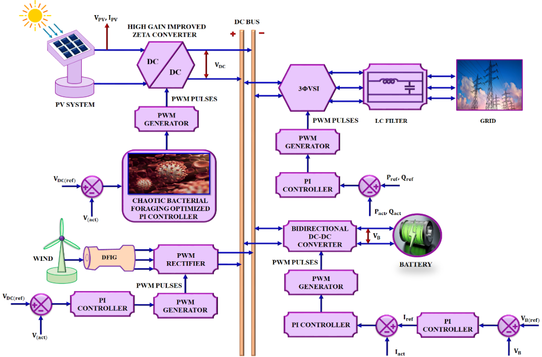
The HRES based grid system with battery is illustrated in Figure 1. At the beginning, the PV system produces the reduced voltage because of the ecological changes, which is solved by exploiting High gain improved Zeta converter that enhances the voltage into the needed level. This converter is regulated by PWM pulses produced via a PWM generator that takes its reference signal from a Chaotic Bacterial Foraging optimized PI controller, which compares actual and reference voltage to manage the developed converter effectively.
Figure 1. Proposed block diagram
This research utilizes another RES called DFIG based WECS produces the AC power, and the PWM rectifier transforms it into DC power. The output of both PV and WECS are fed into the  Voltage Source Inverter (VSI) that changes DC to AC power for grid interfacing. Then, an LC filter removes the unnecessary harmonics before send it to the grid. This inverter’s function is managed by a PWM generator and a PI controller modify its function according to the difference among actual and reference active and reactive power values. The hybrid approach enables the system to adjust to fluctuating power generation from renewable sources though sustaining a grid stability and battery management. Figure 2 shows the flowchart of developed research.
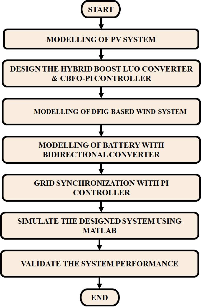
Figure 2. Flowchart of developed research
PV System
Figure 3 represents the PV system’s equivalent circuit. The PV system transforms the sunlight into electrical energy. The PV panel’s I-V characteristics exploited in this research is depicted by a single diode model. Where, parallel and series resistances are denoted by  and
and  , band gap’s energy (minimum energy of photon) is
  , solar radiation level is
  , number of cells in parallel is
  diode’s ideality factor is
  , charge of an electron is
  , , reverse saturation current is
  , Boltzmann constant is
  , photocurrent is
  , short-circuit current is
  , reference temperature is
  , surface temperature is
  , current and voltage is
  and
and  and series coupled cell is
  . The PV system’s output voltage is sometimes varied due to the changes of environment and is resolved by utilizing HGIZC converter.
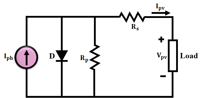
Figure 3. PV system’s equivalent circuit
High Gain Improved Zeta Converter
The high gain improved Zeta converter play a vital role in PV systems by efficiently addressing the challenges linked with low output voltages, energy conversion efficiency and stability. The HGIZC is represented in Figure 4 and it has 2 stages according to the semiconductor switch’s non-conducting conditions.
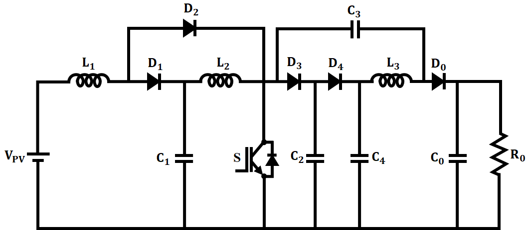
Figure 4. Circuit of HGIZC
Mode 1: The input supply  charges the inductor
  and makes a closed circuit with diode
  whereas diode
 is inactive. Capacitor
  charges
  .
.  and
and  are linked in series by the conducting state of diode
  and non-conducting state of the diode
 . Then, the closed circuit is developed by parallel connection of
  and load is fed from output capacitor
 . Subsequently,
  and
and  are in off state. The switching waveform of HGIZC is illustrated in Figure 5. By applying KVL,
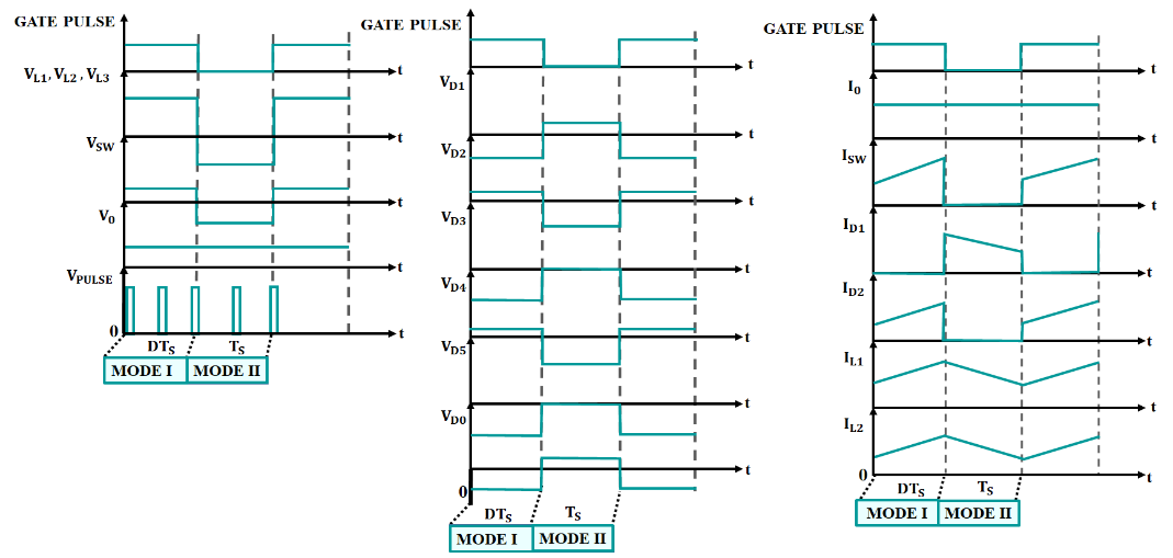
Figure 5. Waveform of developed converter
Table 1. Analysis of 2 modes
Stages | Stage 1 | Stage 2 |
Switch | ON | OFF |
Forward biased diodes | 
| and |
Reverse biased diodes | and |
|
Mode 2: During this mode, the load is discharged by input supply  along with inductors
 . Here,
  and
and  transfers into the conduction state and
  and
and  are in blocking state, as seen in Figure 6. The output voltage is same to
 .
.
The current gain is,
| 
| (11) |
The design expression of the inductors in the developed topology is,
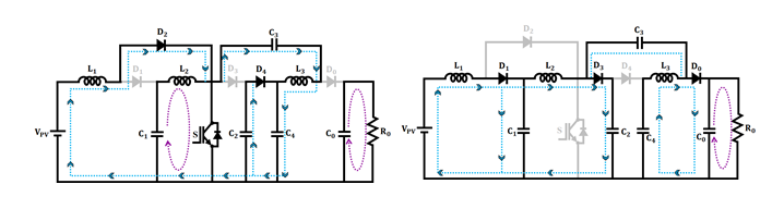
Figure 6. Stages of developed converter
The capacitor values are,
However, the voltage of developed converter is unstable and is resolved by utilizing CBFO-PI controller.
CBFO-PI Controller
The CBFO-PI controller is a sophisticated control approach exploited in PV systems to improve their performance. This optimized PI controller guarantees improved voltage stability and effective power management. The tuning of  and
and  utilizing CBFO algorithm comprises numerous phases where the chaos theory is incorporated into the BFO algorithm to enhance convergence and avoid local optima. The fitness function is,
| 
| (20) |
In initialization phase, the bacterial population, which indicates  and
and  is initiated utilizing logistic chaotic mapping to assure search space’s better coverage. The chaotic population mapping is,
| 
| (21) |
Table 2. Parameters of CBFO-PI controller
Parameters | Value |
Size of population | 50 |
Loud ness | 0.5 |
Maximum generation | 500 |
Frequency | [0 2] |
Pulse rate | 0.5 |

| [-1,1] |
Where, original population’s position is  , size of population is and corresponding chaotic population is
  . The top performing individuals are choosed to make the initial bacterial population amid the original and chaotic mapped candidates. This phase assures an effective and well distributed starting point for the search process of best and values. In chemotaxis phase, each bacterium performs swimming and tumbling and chaotic local search is incorporated to exploit the search space around the best bacterium found. The movement of bacterium is,
| 
| (22) |
| 
| (23) |
The detailed flowchart of CBFO-PI controller is shown in Figure 7. Where, random direction vector is  and bacterium’s position is
  and step size is
 . The shrinking strategy is utilized to refine and parameters in the vicinity of best solution found. If a new position gives better fitness, the bacterium remains swimming in the same direction or else it tumbles again to search a new direction. The chaotic sequence is mapped into the search space is,
| 
| (24) |
Where, upper and lower bounds for and is  . By linearly integrating the chaotic vector with current global best position, a new candidate solution is produced utilizing a shrinking strategy.
| 
| (25) |
Where, chaotic position candidate is  and global best position is
 . The shrinking contraction factor is,
| 
| (26) |
Where, maximum iteration is denoted by  and current iteration count is
  . This stage aids escape local minima early and fine tunes and values. Then, the reproduction phase is initiated after a fixed number of chemotaxis steps. The fitness of each bacterium is with its lifetime is accumulated and bacteria sorted by performance. The top 50% are duplicated and least fit 50% of population are discarded to sustain a stable population size. It aids reinforce successful parameter configurations and overwhelms the poor ones. For averting premature convergence and enable escape from local minima, an elimination dispersal operation is applied. It introduce diversity and allow the discovery of possibly unexplored, better regions for best and values. The chaotic elements enhance global search in early stages and local refinement in later stages, assuring both high accuracy and fast convergence in tuning of and values. The algorithm is concluded if it predict the ideal parameter values. To enhance the performance of overall system, another RES (WECS) is employed in this research.
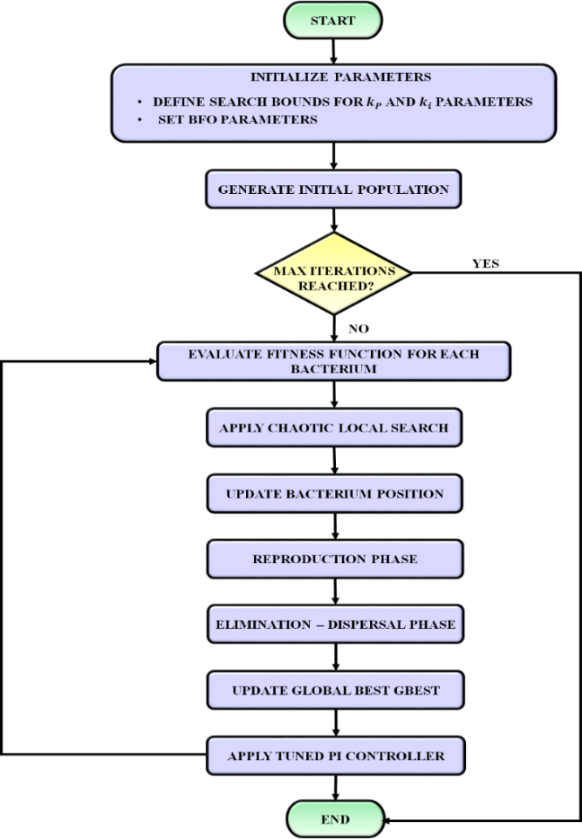
Figure 7. Flowchart of CBFO-PI controller
DFIG-WECS
The combination of stator and rotor windings makes the DFIG. The dynamic model of the DFIG is represented by the direct and inverse transformation. 2 windings, for the rotor and
 for the stator are utilized to denote the 3 windings of the stator and rotor exploiting space vector theory. The rotor and stator voltage vector is,
In the  frame,
 and
and  stand for the stator and rotor voltages. The stator and rotor currents in the frame are signified by
  and
and .
. and
and : angular velocity and phase resistances of the stator and rotor. Figure 8 represents the equivalent. The stator and rotor flux vector are,
Where the fluxes along the  axis stator are signified by
  and
and . Together with the axis rotor, the fluxes are denoted by
  and
and  .
.  is the stator and rotor’s mutual inductance,
 and
and  are the rotor and stator phase leakage inductances and
  is the generator's pole pairs. The electromagnetic torque is,
| 
| (35) |
The active and reactive power are,
Where, active and reactive power of rotor and stator is  and
and , electromagnetic torque is
 . The basic torque equation is,
| 
| (40) |
Where, speed of rotor is , rotor’s inertia is
  and load torque applied to the shaft is
 . Then, the Battery Energy Storage System (BESS) is exploited to store the excess energy from BESS that is discussed below.
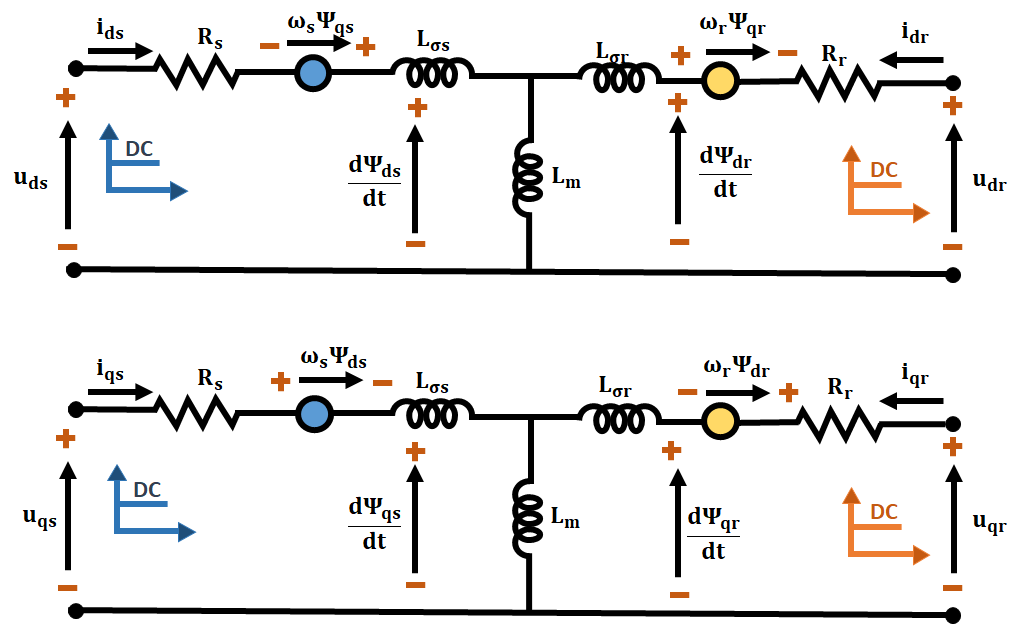
Figure 8. DFIG equivalent circuit
BESS
The BESS to reserve excess energy caused by RES and deliver it to the grid when the energy from solar and wind energy sources is not enough to fulfill load demands. The State of charge (SOC) is,
| 
| (41) |
Where, capacity of battery is  and battery current is
 . The battery functions on charging and discharging stages that is defined by their SOC limits.
| 
| (42) |
Batteries are used to store solar and wind energy during excess production and to use in times of energy scarcity. A Bidirectional Converter (BDC) is used in these applications to deliver power among 2 sources in any direction. The BDC circuit diagram is displayed in Figure 9. The bidirectional converter act as a boost converter provides the gate signal to S2 when the power from HRES is low. It act as a buck converter offers the gate signal to S1.
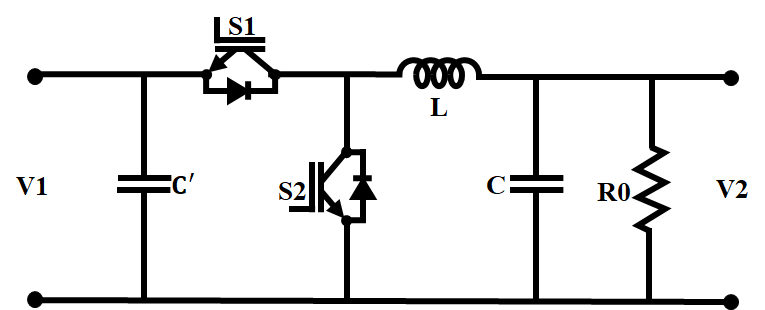
Figure 9. BDC’s circuit diagram
RESULT AND DISCUSSION
This section analyze the outcomes of hybrid renewable energy management system with HGIZC converter in MATLAB/Simulink software and comparative analysis is also included to proves its performance. Table 3 provides the parameter’s specification.
Table 3. Specification of parameters
Parameter | Specification |
PV System |
Total Power | 
|
Panel’s peak power | 
|
Voltage (Open circuit ) | 22.6V |
Maximum Peak Current | 
|
Maximum Peak Voltage | 
|
Voltage ( Short circuit) | 12V |
series connection | 5 |
parallel connection | 8 |
HGIZC Converter |

| 
|

| 
|

| 2200𝜇𝐹 |
Switching Frequency | 10 kHz |
Case 1: Persistent intensity and temperature
Figure 10 signifies the solar panel’s characteristics in persistent intensity and temperature scenario. The temperature is continued at  in the complete system. The intensity of solar is sustained at
  without distortions. Also, the voltage is settled at
  throughout the system. Subsequently, the current has suddenly decreased and is maintained at
  in the entire system. These characteristics of solar panel decides the output performance of HGIZC converter. An output waveform of HGIZC converter is illustrated in Figure 11. The voltage on output side has progressively elevated and with the help of CBSO-PI controller, it settled at
  in the entire system. Likewise, an output current has random variations and maintained at
  with little distortions.
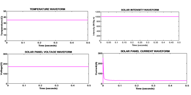
Figure 10. Characteristics of PV system
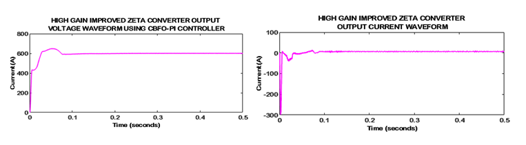
Figure 11. Output waveform of developed converter
Case 2: Varying intensity and temperature
The behaviour of solar panel in case 2 is depicted in Figure 12. Primarily, the temperature is increased and then, it sustained at without oscillations. Meanwhile, the intensity of solar panel has gradually enlarged and maintained at  in the complete system. Then, the voltage of solar panel has slow variations in an initial stage and settled at
 . Subsequently, the current of solar panel is slowly changed and is settled at
  with little distortions.
Figure 13 displays an output waveform of HGIZC converter. With the aid of CBFO-PI controller, an output voltage of HGIZC is stabilized at without distortions. Then, the output current is randomly changed and is maintained at
  with little oscillations. An output voltage waveform of DFIG is revealed in Figure 14. Here, the output voltage of DFIG is gradually enhanced and is reached a unity value.
A waveform of output voltage for PWM rectifier is presented in Figure 15. At the beginning, an output voltage is arbitrarily changed and is maintained at throughout the system.
Figure 16. represents the waveform of battery. The current of battery is varied and is settled at a small value. Meanwhile, the voltage is maintained at  without oscillations. Consequently, the SOC of battery is sustained at
  throughout the system. The voltage of grid is maintained a stable value of
  as depicted in Figure 17. Likewise, the current of grid is sustained at
  in the system. Consequently, an Inphase voltage and current of grid is settled at
  .
.
The waveform of power is demonstrated in Figure 18. The value of real power is settled at  and reactive power is maintained at
  in the entire system, sustaining voltage stability and allowing the smooth flow of real power within the electrical grid. Figure 19 displays the waveform of Total Harmonic Distortion (THD). The developed approach has the lowest THD of
  enhancing the power quality.
The comparison of efficiency for Zeta [49], Interleaved Boost [50] and developed converter is shown in Figure 20. This developed with voltage multiplier cell converter has an efficiency improvement of  denoting the better performance in energy conversion. Then, the IBC has an efficacy of 96.04%, reflects the slightly lower performance than developed converter. Also, the Zeta converter has the lowest efficiency of 90 % than other 2 approaches, emphasizes the effectiveness of the proposed technique in enhancing overall efficiency in power conversion systems.
The comparison of voltage gain for Non-isolated [51], Coupled inductor-high gain [52], High step-up [53] and HGIZC converter is represented in Figure 21. The HGIZC converter has the maximum voltage gain than other converters. Particularly beyond a duty cycle of 0.6, the developed system attains the highest voltage gain, exceeding 60 at 0.8 duty cycle, highlights the better step-up capability and scalability of the developed converter, making it highly appropriate for requiring high voltage gain applications.
Figure 22 represents an analysis of voltage stress on switch for high gain [54], high step-up [55], single switch high step-up [56] and developed converter. Here, the developed converter constantly reveals the lowest voltage stress in the entire range of duty cycles, which highlights its superior design in minimizing switching stress. In contrast, the high voltage gain converter has the highest voltage stress, particularly at lower duty cycles, which result in lowest reliability and enhanced switching losses. The Single Switch and High Step-Up converters show moderate stress levels, but they are still noticeably higher than the proposed approach. This comparison indicates that the developed converter improves the reliability and efficiency of system.
The comparative analysis of voltage stress on diode for high voltage gain [54], high step-up [55], single switch high step-up [56] and HGIZC converter is illustrated in Figure 23. The HGIZC converter has the minimum voltage stress on diode than others that indicates the performance of system is enhanced. It specifies that the developed converter is highly effective in minimizing diode stress, enhancing the converter's reliability, reducing power losses and enhancing component lifespan, specifically in high step-up applications.
The developed Chaotic Bacterial Foraging optimized PI controller attains the better settling time of than Crow Search (CS)-PI [57] and Lion Grey Wolf Optimization (LGWO)-PI [58] approaches, as exposed in Figure 24. The LGWO-PI controller has a moderate settling time of 0.05 seconds, showcasing improved behavior over traditional tuning methods. However, the CS-PI controller exhibits the highest settling time of 0.1 seconds, implying slower convergence to steady-state. It highlights that the proposed control strategy provides the most efficient transient response, which is essential in applications where fast stabilization is critical, such as RES, converters and real-time control applications. Thus, the overall system attains the maximum voltage with the presence of HGIZC converter and stable voltage with the presence of CBFO-PI controller and enables the continuous power supply to grid.
The comparison between Synchronous boost [59], Interleaved high step-up [60] and HGIZC converter is shown in Table 4. The HGIZC converter has lowest component count of 14 than existing converters, indicting the cost of HGIZC converter is reduced.
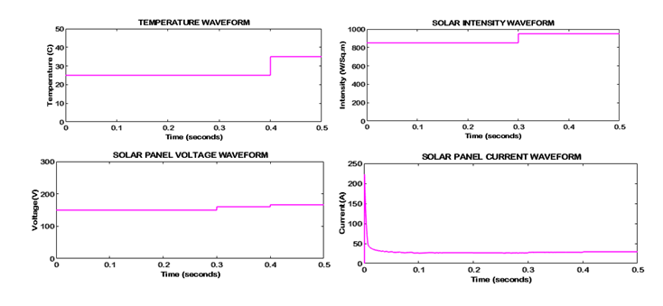
Figure 12. Behaviour of solar panel
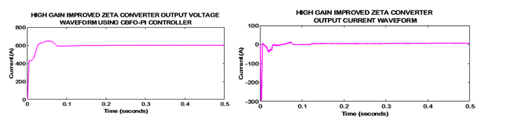
Figure 13. Output waveform of developed converter
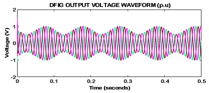
Figure 14. Output voltage waveform of DFIG
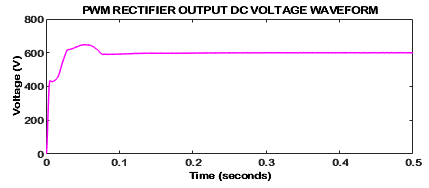
Figure 15. Output voltage waveform of PWM rectifier
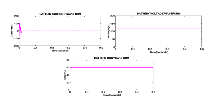
Figure 16. Waveform of battery
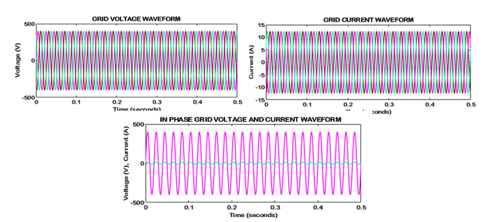
Figure 17. Waveform of grid
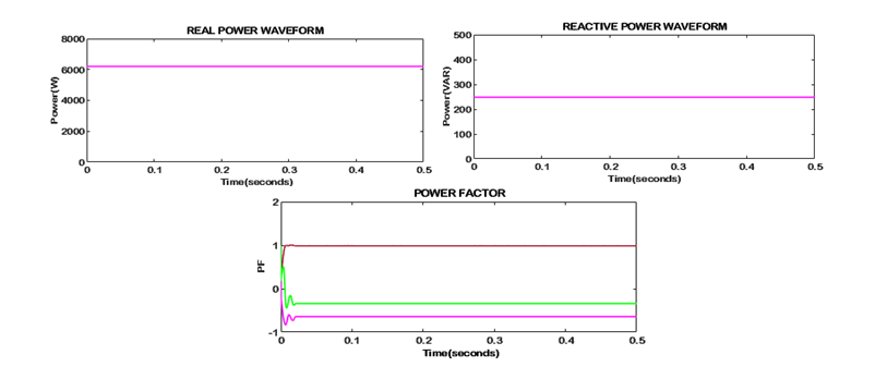
Figure 18. Waveform of power
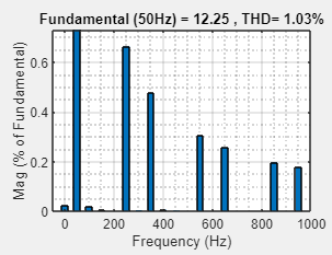
Figure 19. Waveform of THD
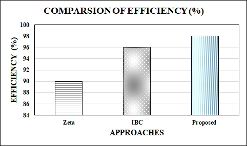
Figure 20. Comparison of efficiency
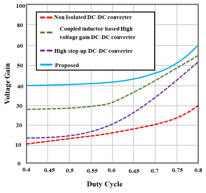
Figure 21. Comparison of voltage gain
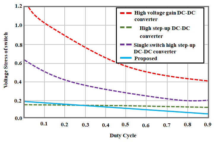
Figure 22. Analysis of voltage stress in switch
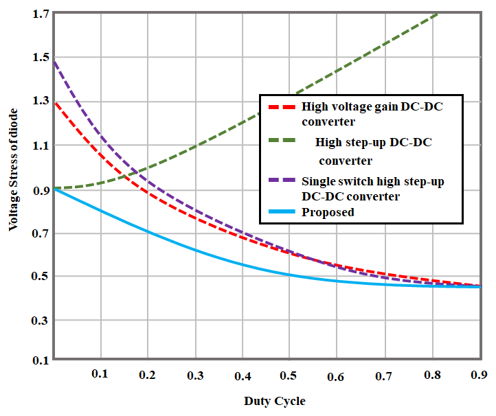
Figure 23. Analysis of voltage stress on diode
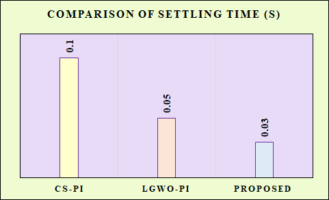
Figure 24. Comparison between PI controllers
Table 4. Comparison between converters
CONVERTERS | D/I/C/S |
Synchronous boost converter [59] | 0/6/1/12 |
Interleaved high step-up converter [60] | 10/4/4/2 |
HGIZC converter | 5/3/5/1 |
CONCLUSION
For addressing the instability caused by intermittent renewable sources, a HRES based microgrid that integrates PV and WECS is developed in this research. The developed HGIZC converter has the benefit enhancing the voltage with high voltage gain, low thermal stress and voltage stress on switch. Subsequently, the CBFO-PI controller is exploited to assure a fluctuation-less and incessant voltage supply from the converter. The battery, which is contacted with the microgrid over a battery converter, guarantees stable supply of power. Here, the outcomes of developed research is obtained from MATLAB/Simulink and efficacy of developed control method in sustaining power quality and micro grid’s strength is verified. It reveals that the developed converter contributes an efficacy of  compared to existing state-of-the-art approaches with THD of
 , reveals an effective energy storage management system with reducing emissions. The implementation of hardware-in-the-loop validation will be included in the future research. The predicted values of THD and efficiency are obtained from simulation tool and may differ in hardware implementation. To further enhance the performance of overall system, more RES and storage systems are needed.
REFERENCES
- H. T. Dinh, J. Yun, D. M. Kim, K. H. Lee and D. Kim, "A home energy management system with renewable energy and energy storage utilizing main grid and electricity selling," IEEE access, vol. 8, pp. 49436-49450, 2020, https://doi.org/10.1109/ACCESS.2020.2979189.
- A. Kechida, D. Gozim, B. Toual, M. M. Alharthi, T. F. Agajie, S. S. Ghoneim and R. N. Ghaly, "Smart control and management for a renewable energy based stand-alone hybrid system," Scientific Reports, vol. 14, no. 1, pp. 32039, 2024, https://doi.org/10.1038/s41598-024-83826-1.
- T. Al Smadi, A. Handam, K. S. Gaeid, A. Al-Smadi, Y. Al-Husban and A. smadi Khalid, "Artificial intelligent control of energy management PV system," Results in Control and Optimization, vol. 14, pp. 100343, 2024, https://doi.org/10.1016/j.rico.2023.100343.
- M. E. Shayan, G. Najafi, B. Ghobadian, S. Gorjian and M.Mazlan, "A novel approach of synchronization of the sustainable grid with an intelligent local hybrid renewable energy control," International Journal of Energy and Environmental Engineering, vol. 14, no. 1, pp. 35-46, 2023, https://doi.org/10.1007/s40095-022-00503-7.
- B. S. Sami, "Intelligent energy management for off-grid renewable hybrid system using multi-agent approach," IEEE Access, vol. 8, pp. 8681-8696, 2020, https://doi.org/10.1109/ACCESS.2019.2963584.
- M. Saadi, D. Djalel, B. Meghni, and D. Rekioua, "Intelligent Energy Management Strategy and Sizing Methodology for Hybrid Systems in Isolated Regions," Chinese Journal of Electrical Engineering, vol. 10, no. 3, pp. 50-62, 2024, https://doi.org/10.23919/CJEE.2024.000091.
- M. Talaat, M. H. Elkholy, A. Alblawi and T. Said, "Artificial intelligence applications for microgrids integration and management of hybrid renewable energy sources," Artificial Intelligence Review, vol. 56, no. 9, pp. 10557-10611, 2023, https://doi.org/10.1007/s10462-023-10410-w.
- I. E. Atawi, A. Q. Al-Shetwi, A. M. Magableh and O. H. Albalawi, "Recent advances in hybrid energy storage system integrated renewable power generation: Configuration, control, applications, and future directions," Batteries, vol. 9, no. 1, pp. 29, 2022, https://doi.org/10.3390/batteries9010029.
- M. M. Gulzar, M. Iqbal, S. Shahzad, H. A. Muqeet, M. Shahzad and M. M. Hussain, "Load frequency control (LFC) strategies in renewable energy-based hybrid power systems: A review," Energies, vol. 15, no. 10, pp. 3488, 2022, https://doi.org/10.3390/en15103488.
- H. El Hafdaoui, A. Khallaayoun, and S. AIMajeed, "Controlled Non-Dominated Sorting Genetic Algorithms for Multi-Objective Optimal Design of Standalone and Grid-Connected Renewable Energy Systems in Integrated Energy Sectors," IEEE Access, vol. 13, pp. 14658-14685, 2025, https://doi.org/10.1109/ACCESS.2025.3530084.
- K. S. Kavin, P. Subha Karuvelam, M. Devesh Raj, and M. Sivasubramanian, "A novel KSK converter with machine learning MPPT for PV applications," Electric Power Components and Systems, pp. 1-19, 2024, https://doi.org/10.1080/15325008.2024.2346806.
- K. A. Al Sumarmad, N. Sulaiman, N. I. A. Wahab and H. Hizam, "Energy management and voltage control in microgrids using artificial neural networks, PID, and fuzzy logic controllers," Energies, vol. 15, no. 1, pp. 303, 2022, https://doi.org/10.3390/en15010303.
- M. I. Mosaad, H. S. M. Ramadan, M. Aljohani, M. F. El-Naggar and S. S. Ghoneim, "Near-optimal PI controllers of STATCOM for efficient hybrid renewable power system," IEEE Access, vol. 9, pp. 34119-34130, 2021, https://doi.org/10.1109/ACCESS.2021.3058081.
- M. B. Abdelghany, A. Al-Durra and F. Gao, "A coordinated optimal operation of a grid-connected wind-solar microgrid incorporating hybrid energy storage management systems," IEEE Transactions on Sustainable Energy, vol. 15, no. 1, pp. 39-51, 2023, https://doi.org/10.1109/TSTE.2023.3263540.
- V. V. Murty, and A. Kumar, "Optimal energy management and techno-economic analysis in microgrid with hybrid renewable energy sources," Journal of Modern Power Systems and Clean Energy, vol. 8, no. 5, pp. 929-940, 2020, https://doi.org/10.35833/MPCE.2020.000273.
- M. U. Saleem, M. Shakir, M. R. Usman, M. H. T. Bajwa, N. Shabbir, P. Shams Ghahfarokhi and K. Daniel, "Integrating smart energy management system with internet of things and cloud computing for efficient demand side management in smart grids," Energies, vol. 16, no. 12, pp. 4835, 2023, https://doi.org/10.3390/en16124835.
- M. Hassan, "Machine learning optimization for hybrid electric vehicle charging in renewable microgrids," Scientific Reports, vol. 14, no. 1, pp. 13973, 2024, https://doi.org/10.1038/s41598-024-63775-5.
- Y. Boujoudar, M. Azeroual, L. Eliysaouy, F. Z. Bassine, A. J. Albarakati, A. Aljarbouh, A. Knyazkov, H. El Moussaoui and T. Lamhamdi, "Fuzzy logic-based controller of the bidirectional direct current to direct current converter in microgrid," Int. J. Elect. Computer Syst. Eng, vol. 13, no. 5, pp. 4789-4797, 2023, https://doi.org/10.11591/ijece.v13i5.pp4789-4797.
- M. Davari, W. Gao, A. Aghazadeh, F. Blaabjerg and F. L. Lewis, "An Optimal Synchronization Control Method of PLL Utilizing Adaptive Dynamic Programming to Synchronize Inverter-Based Resources With Unbalanced, Low-Inertia, and Very Weak Grids," in IEEE Transactions on Automation Science and Engineering, vol. 22, pp. 24-42, 2025, https://doi.org/10.1109/TASE.2023.3329479.
- Z. Zhao, J. Guo, X. Luo, C. S. Lai, P. Yang, L. L. Lai, P. Li, J. M. Guerrero and M. Shahidehpour, "Distributed robust model predictive control-based energy management strategy for islanded multi-microgrids considering uncertainty," IEEE Transactions on Smart Grid, vol. 13, no. 3, pp. 2107-2120, 2022, https://doi.org/10.1109/TSG.2022.3147370.
- K. S. Kavin, P. S. Karuvelam, M. Matcha, and S. Vendoti, "Improved BRBFNN-based MPPT algorithm for coupled inductor KSK converter for sustainable PV system applications," Electrical Engineering, pp. 1-23, 2025, https://doi.org/10.1007/s00202-025-02952-9.
- J. Wang, J. Zhou and W. Zhao, "Deep reinforcement learning based energy management strategy for fuel cell/battery/supercapacitor powered electric vehicle," Green Energy and Intelligent Transportation, vol. 1, no. 2, pp. 100028, 2022, https://doi.org/10.1016/j.geits.2022.100028.
- O. F. Orikpete, S. Ikemba and D. R. E. Ewim, "Integration of renewable energy technologies in smart building design for enhanced energy efficiency and self-sufficiency," The Journal of Engineering and Exact Sciences, vol. 9, no. 9, pp. 16423-01e, 2023, https://doi.org/10.18540/jcecvl9iss9pp16423-01e.
- T. Lan, K. Jermsittiparsert, T. Alrashood, S. Rezaei, M., L. Al-Ghussain and M. A. Mohamed, "An advanced machine learning based energy management of renewable microgrids considering hybrid electric vehicles’ charging demand," Energies, vol. 14, no. 3, pp. 569, 2021, https://doi.org/10.3390/en14030569.
- Y. Sahri, Y. Belkhier, S. Tamalouzt, N. Ullah, R. N. Shaw, M. S. Chowdhury and K. Techato, "Energy management system for hybrid PV/wind/battery/fuel cell in microgrid-based hydrogen and economical hybrid battery/super capacitor energy storage," Energies, vol. 14, no. 18, pp. 5722, 2021, https://doi.org/10.3390/en14185722.
- D. Mazzeo, M. S. Herdem, N. Matera, M. Bonini, J. Z. Wen, J. Nathwani and G. Oliveti, "Artificial intelligence application for the performance prediction of a clean energy community," Energy, vol. 232, pp. 120999, 2021, https://doi.org/10.1016/j.energy.2021.120999.
- J. Liu, H. Hu, S. S. Yu and H. Trinh, "Virtual power plant with renewable energy sources and energy storage systems for sustainable power grid-formation, control techniques and demand response," Energies, vol. 16, no. 9, pp. 3705, 2023, https://doi.org/10.3390/en16093705.
- J. Liu, H. Hu, S. S. Yu and H. Trinh, "Virtual power plant with renewable energy sources and energy storage systems for sustainable power grid-formation, control techniques and demand response," Energies, vol. 16, no. 9, pp. 3705, 2023, https://doi.org/10.3390/en16093705.
- A. Saxena, R. Shankar, E. F. El-Saadany, M. Kumar, O. Al Zaabi, K. Al Hosani and U. R. Muduli, "Intelligent load forecasting and renewable energy integration for enhanced grid reliability," IEEE Transactions on Industry Applications, vol. 60, no. 6, pp. 8403-8417, 2024, https://doi.org/10.1109/TIA.2024.3436471.
- M. M. Gulzar, A. Iqbal, D. Sibtain, and M. Khalid, "An innovative converterless solar PV control strategy for a grid connected hybrid PV/wind/fuel-cell system coupled with battery energy storage," IEEE Access, vol. 11, pp. 23245-23259, 2023, https://doi.org/10.1109/ACCESS.2023.3252891.
- Z. Chen, Y. Liu, Y. Zhang, Z. Lei, Z. Chen and G. Li, "A neural network-based ECMS for optimized energy management of plug-in hybrid electric vehicles," Energy, vol. 243, pp. 122727, 2022, https://doi.org/10.1016/j.energy.2021.122727.
- E. T. Sayed, A. G. Olabi, A. H. Alami, A. Radwan, A. Mdallal, A. Rezk and M. A. Abdelkareem, "Renewable energy and energy storage systems," Energies, vol. 16, no. 3, pp. 1415, 2023, https://doi.org/10.3390/en16031415.
- M. M. Gulzar, A. Iqbal, D. Sibtain and M. Khalid, "An innovative converterless solar PV control strategy for a grid connected hybrid PV/wind/fuel-cell system coupled with battery energy storage," IEEE Access, vol. 11, pp. 23245-23259, 2023, https://doi.org/10.1109/ACCESS.2023.3252891.
- M. Kermani, B. Adelmanesh, E. Shirdare, C. A. Sima, D. L. Carnì and L. Martirano, "Intelligent energy management based on SCADA system in a real Microgrid for smart building applications," Renewable Energy, vol. 171, pp. 1115-1127, 2021, https://doi.org/10.1016/j.renene.2021.03.008.
- C. Srisailam, and M. Manjula, "Optimized FOPID controller for transient stability improvement in a microgrid with energy storage," SSRG Int J Electr Electron Eng, vol. 10, no. 2, pp. 19-34, 2023, https://doi.org/10.14445/23488379/IJEEE-V10I2P103.
- A. Raj, and R. P. Praveen, "Highly efficient DC-DC boost converter implemented with improved MPPT algorithm for utility level photovoltaic applications," Ain Shams Engineering Journal, vol. 13, no. 3, pp. 101617, 2022, https://doi.org/10.1016/j.asej.2021.10.012.
- M. I. Guerra, F. M. Ugulino de Araújo, M. Dhimish, and R. G. Vieira, "Assessing maximum power point tracking intelligent techniques on a PV system with a buck–boost converter," Energies, vol. 14, no. 22, pp. 7453, 2021, https://doi.org/10.3390/en14227453.
- H. C. Mohanta, B. T. Geetha, M. S. Alzaidi, I. S. Dhanoa, P. Bhambri, U. Mamodiya, and R. Akwafo, "An Optimized PI Controller‐Based SEPIC Converter for Microgrid‐Interactive Hybrid Renewable Power Sources," Wireless Communications and Mobile Computing, vol. 2022, no. 1, pp. 6574825, 2022, https://doi.org/10.1155/2022/6574825.
- K. Joshi, V. Raut, S. Waghmare, M. Waje, and R. Patil, "Maximum power operation of a PV system employing zeta converter with modified P&O algorithm," International Journal of Engineering Trends and Technology, vol. 70, no. 7, pp. 348-354, 2022, https://doi.org/10.14445/22315381/IJETT-V70I7P236.
- M. Mavrinac, I. Lorencin, Z. Car, and M. Šercer, "Genetic algorithm-based parametrization of a pi controller for dc motor control," Tehnički glasnik, vol. 16, no. 1, pp. 16-22, 2022, https://doi.org/10.31803//tg-20201119185015.
- M. G. Abdolrasol, M. A. Hannan, S. S. Hussain, and T. S. Ustun, "Optimal PI controller based PSO optimization for PV inverter using SPWM techniques," Energy Reports, vol. 8, pp. 1003-1011, 2022, https://doi.org/10.1016/j.egyr.2021.11.180.
- M. Fodil, A. Djerioui, M. Ladjal, A. Saim, F. Berrabah, H. Mekki, S. Zeghlache, A. Houari, and M. F. Benkhoris, "Optimization of PI controller parameters by GWO algorithm for five-phase asynchronous motor," Energies, vol. 16, no. 10, pp. 4251, 2023, https://doi.org/10.3390/en16104251.
- N. K. Kumar, R. S. Gopi, R. Kuppusamy, S. Nikolovski, Y. Teekaraman, I. Vairavasundaram, and S. Venkateswarulu, "Fuzzy logic-based load frequency control in an island hybrid power system model using artificial bee colony optimization," Energies, vol. 15, no. 6, pp. 2199, 2022, https://doi.org/10.3390/en15062199.
- M. Althani, A. Maheri, "An ant colony algorithm for HRES size and configuration optimisation," In 2021 6th International Symposium on Environment-Friendly Energies and Applications (EFEA), pp. 1-6, 2021, https://doi.org/10.1109/EFEA49713.2021.9406256.
- H. Dong, M. Su, K. Liu, and W. Zou, "Mitigation strategy of subsynchronous oscillation based on fractional-order sliding mode control for VSC-MTDC systems with DFIG-based wind farm access," IEEE Access, vol. 8, pp. 209242-209250, 2020, https://doi.org/10.1109/ACCESS.2020.3038665.
- R. K. Behara, and A. K. Saha, "Deep Q-Network Reinforcement Learning Based Rotor Side Control System of A Grid Integrated DFIG Wind Energy System Under Variable Wind Speed Conditions," IEEE Access, vol. 12, pp. 184179-184205, 2024, https://doi.org/10.1109/ACCESS.2024.3511665.
- T. Cheng, J. Wu, H. Wang, and H. Zheng, "Dynamic optimization of rotor-side PI controller parameters for doubly-fed wind turbines based on improved recurrent neural networks under wind speed fluctuations," IEEE Access, vol. 11, pp. 102713-102726, 2023, https://doi.org/10.1109/ACCESS.2023.3315590.
- M. M. Gulzar, A. Iqbal, D. Sibtain, and M. Khalid, "An innovative converterless solar PV control strategy for a grid connected hybrid PV/wind/fuel-cell system coupled with battery energy storage," IEEE Access, vol. 11, pp. 23245-23259, 2023, https://doi.org/10.1109/ACCESS.2023.3252891.
- S. Saravanan, P. Usha Rani, and M. P. Thakre, "Evaluation and Improvement of a Transformerless High-Efficiency DC–DC Converter for Renewable Energy Applications Employing a Fuzzy Logic Controller," MAPAN, pp. 1-20, 2022, https://doi.org/10.20944/preprints202110.0420.v1.
- P. Balakishan, I. A. Chidambaram, and M. Manikandan, "An ANN Based MPPT for Power Monitoring in Smart Grid using Interleaved Boost Converter," Tehnički vjesnik, vol. 30, no. 2, pp. 381-389, 2023, https://doi.org/10.17559/TV-20220820194302.
- G. H. De Alcântara Bastos, L. F. Costa, F. L. Tofoli, G. V. T. Bascopé, and R. P. T. Bascopé, "Nonisolated DC–DC converters with wide conversion range for high-power applications,” IEEE Journal of Emerging and Selected Topics in Power Electronics, vol. 8, no. 1, pp. 749–760, 2020, https://doi.org/10.1109/JESTPE.2019.2892977.
- A. Mirzaee, and J. S. Moghani, "Coupled inductor-based high voltage gain DC–DC converter for renewable energy applications," IEEE Trans. Power Electron, vol. 35, no. 7, pp. 7045–7057, 2020, https://doi.org/10.1109/TPEL.2019.2956098.
- H. Tarzamni, P. Kolahian, and M. Sabahi, "High step-up DC–DC converter with efficient inductive utilization," IEEE Transactions on Industrial Electronics, vol. 68, no. 5, pp. 3831-3839, 2020, https://doi.org/10.1109/TIE.2020.2987253.
- A. Imanlou, E. Seifi Najmi, and E. Babaei, "A new high voltage gain DC‐DC converter based on active switched‐inductor technique," International Journal of Circuit Theory and Applications, vol. 52, no. 2, pp. 634-657, 2024, https://doi.org/10.1002/cta.3768.
- S. Hasanpour, Y. P. Siwakoti, A. Mostaan, and F. Blaabjerg, "New semiquadratic high step-up DC/DC converter for renewable energy applications," IEEE Transactions on Power Electronics, vol. 36, no. 1, pp. 433-446, 2020, https://doi.org/10.1109/TPEL.2020.2999402.
- A. V. Pereira, M. C. Cavalcanti, G. M. Azevedo, F Bradaschia, R. C. Neto, and M. R. Carvalho, "A novel single-switch high step-up dc–dc converter with three-winding coupled inductor," Energies, vol. 14, no. 19, pp. 6288, 2021, https://doi.org/10.3390/en14196288.
- Y. R. Sankar, and K. C. Sekhar, "Hybrid PV/fuel cell based system using integrated SEPIC-Cuk converter with crow search optimized PI controller," International Journal of Power Electronics and Drive Systems (IJPEDS), vol. 15, no. 3, pp. 1726-1738, 2024, https://doi.org/10.11591/ijpeds.v15.i3.pp1726-1738.
- J. A. Glenn, and S. Alavandar, "Hybrid optimized PI controller design for grid tied PV based electric vehicle," Intell Autom Soft Comput, vol. 36, no. 2, pp. 1523-1545, 2023, https://doi.org/10.32604/iasc.2023.033545.
- M. Rimondi, R. Mandrioli, V. Cirimele, L. K. Pittala, M. Ricco and G. Grandi, "Design of an integrated, six-phase, interleaved, synchronous DC/DCboostconverter on a fuel-cell-powered sport catamaran," Designs, vol. 6, no. 6, pp. 113, 2022, https://doi.org/10.3390/designs6060113.
- J. Tang, Z. Qi, L. Shan, W. Ye and C. Zhao, "An innovative interleaved high step-up direct current–direct current converter with switched inductor/capacitor–diode units for hydrogen fuel cell power system," International Journal of Circuit Theory and Applications, vol. 49, no. 9, pp. 3007–3030, 2021, https://doi.org/10.1002/cta.3082.
Siddheswar Kar (Intelligent Control of High Gain Improved Zeta Converter for Hybrid Renewable Energy Management)