Buletin Ilmiah Sarjana Teknik Elektro ISSN: 2685-9572
Vol. 7, No. 4, December 2025, pp. 702-714
A Hybrid PI–SOSM Control Strategy with Disturbance Observer for Enhanced Dynamic Response of IM Drives
Thanh Tinh Pham, Ngoc Thuy Pham
Department of Electrical Engineering Technology, Industrial University of Ho Chi Minh City (IUH), Ho Chi Minh,
Viet Nam
ARTICLE INFORMATION |
| ABSTRACT |
Article History: Received 13 August 2025 Revised 02 October 2025 Accepted 25 October 2025 |
| 
This paper proposes a novel hybrid field-oriented control (FOC) strategy for high-performance induction motor (IM) drives, integrating a conventional Proportional–Integral (PI) controller in the speed loop and a Super-Twisting Second-Order Sliding Mode (SOSM) controller in the current loop. The main novelty lies in combining a sliding mode disturbance observer (OB) with a hybrid PI–SOSM structure, enabling real-time estimation and compensation of unknown load torque. The estimated torque is transformed into an equivalent disturbance current, which is directly added to the torque-producing current reference, thereby achieving feedforward disturbance rejection. The novel hybrid structure achives the improved dynamic response and robustness through self-compensated torque disturbance using OB, reduced chattering in current regulation via SOSM, and maintaining PI simplicity in the outer speed loop. Extensive simulation results by MATLAB/Simulink sotfware demonstrates that the hybrid controller offers superior dynamic performance, enhanced robustness against parameter uncertainties and load disturbances, and significantly reduced chattering effects compared with conventional PI–PI FOC. |
Keywords: Induction Motor Drives; Field-Oriented Control; Super-Twisting Algorithm; Second-Order Sliding Mode; Disturbance Observer |
Corresponding Author: Ngoc Thuy Pham, Department of Electrical Engineering Technology, Industrial University of Ho Chi Minh City (IUH), Ho Chi Minh, Viet Nam. Email: ngocpham1020@gmail.com |
This work is licensed under a Creative Commons Attribution-Share Alike 4.0 
|
Document Citation: T. T. Pham and N. T. Pham, “A Hybrid PI–SOSM Control Strategy with Disturbance Observer for Enhanced Dynamic Response of IM Drives,” Buletin Ilmiah Sarjana Teknik Elektro, vol. 7, no. 4, pp. 702-714, 2025, DOI: 10.12928/biste.v7i4.14458. |
- INTRODUCTION
The three-phase induction motor (IM) has long been recognized as the workhorse of modern industry due to its simple construction, high reliability, low cost, and robust operational capabilities, even in demanding environments [1]-[3]. Over the decades, it has been the backbone of modern industries, electric vehicles, and renewable energy systems [4][5]. However, the IM is inherently a nonlinear, multi-input–multi-output (MIMO) system with parameters that vary under operating conditions, making high-performance control a significant scientific challenge [6]-[8].
To unlock the full potential of IMs, Field-Oriented Control (FOC) was developed and has become the gold standard for high-performance drives [9]-[12]. By transforming the dynamic model from the stationary αβ frame to the synchronous dq frame, FOC decouples the stator current components: the direct-axis current regulates rotor flux, while the quadrature-axis current (isq) controls electromagnetic torque. This decoupling makes the IM behave like a separately excited DC motor, enabling fast torque response and precise speed control [13]-[15]. Conventional FOC typically employs cascaded proportional–integral (PI) controllers for the speed and current loops [16][17]. Despite their simplicity and wide adoption, PI controllers show inherent limitations under modern performance demands. Firstly, PI controllers are linear and tuned for specific operating points. Their performance degrades under load variations, parameter uncertainties, and unmodeled disturbances . Secondly, indirect FOC depends heavily on accurate motor parameters, particularly the rotor time constant ( ). Rotor resistance Rr can vary by up to 100% due to thermal effects, causing slip-frequency miscalculations and inaccurate field orientation. This detuning leads to reduced performance, higher losses, and potential instability. Thirdly, the outer PI speed loop exhibits limited bandwidth, producing sluggish responses to sudden load torque changes [18]-[25]. This results in undesirable speed dips and prolonged recovery times, which are unacceptable in applications requiring high dynamic stiffness, such as CNC machines and robotics [26][27].
To address these challenges, numerous advanced control strategies have been proposed. Nonlinear techniques such as sliding mode control (SMC), backstepping, fuzzy logic, neural networks and model predictive control have been applied to replace PI controllers [28]–[43]. Among them, SMC stands out for its robustness to matched uncertainties and disturbances [44][45]. However, conventional first-order SMC suffers from severe chattering, which induces torque ripples and excites mechanical resonances [46][47]. To mitigate this, second-order sliding mode (SOSM) methods, particularly the super-twisting algorithm, have emerged as effective solutions, eliminating chattering while retaining robustness [48]–[51]. In parallel, disturbance observers (OB) have been developed to estimate and compensate for external disturbances and load torque variations [52][53]. Acting as a feedforward channel, OBs significantly enhance disturbance rejection without affecting closed-loop stability [54][55]. However, a hybrid structure combining PI, SOSM, and a disturbance observer has not been systematically investigated.
Motivated by this analysis, this paper proposes a robust hybrid control structure that combines:
(i) a PI controller for the outer speed loop to ensure zero steady-state error and straight forward tuning; (ii) SOSM controllers based on the super-twisting algorithm for the isd and isq current loops, achieving fast and precise current regulation without chattering; and (iii) a nonlinear disturbance observer that estimates lumped disturbances, including load torque and uncertainties, and feeds forward a compensatory current to the isq reference command. The main contributions of this paper are as follows:
- A composite control structure that synergistically integrates PI, SOSM, and OB, leveraging the strengths of each method to form a high-performance system.
- A detailed SOSM-based current controller that improves transient response and robustness of the inner loop while eliminating chattering.
- An effective nonlinear disturbance observer incorporated as a feedforward compensation channel, enhancing dynamic stiffness and disturbance rejection.
- Comprehensive simulations and experimental verifications, with comparative analysis against conventional schemes, demonstrating the superior performance of the proposed approach.
The remainder of this paper is organized as follows: Section II presents the mathematical model of the IM and the fundamentals of FOC. Section III describes the design of the proposed control structure. Section IV provides simulation and experimental results. Section V concludes the paper.
- MODEL OF IM DRIVES
This drive system consists of a IM supplied by a three-phase voltage source inverter (VSI). In this section, the vector space decomposition (VSD) technique has also been applied as in [2], the original three-dimensional space of IM is converted into two-dimensional spaces in the rotational reference frame (d-q). In that  ;
;  . The model motor dynamics is described by the following space vector differential equations:
| 
| (1) |
where:  : The components of stator voltage and stator current, respectively,
  : Rotor flux components;
  : Electromagnetic and load torque; d-q; D-Q: Synchronous and stationary axis reference frame quantities, respectively;
  : the angular velocity (mechanical speed),
  ;
;  : the electrical speed respectively Rotor and slip angular and synchronous angular velocity;
  : Stator and rotor inductances;
  : Mutual inductance;
  : Stator and rotor resistances;
  : the inertia of motor and load;
  : Total linkage coefficient;
  : Number of pole pairs;
  : Friction coefficient;
  : Rotor and stator time constant. The electromagnetic torque and the slip frequency can be expressed in dq reference frame:
| 
| (2) |
| 
| (3) |
- PI_STSOSM CONTROLLER AND OBSERVER DESIGN
- Speed PI Controller Design
In the outer-loop of the Field-Oriented Control (FOC) structure, a Proportional–Integral (PI) controller is adopted to regulate the rotor speed of the induction motor (IM). The PI controller generates a torque-producing current reference  based on the speed tracking error
  , where
  , are the reference and actual rotor speeds, respectively. The PI speed controller is given by:
| 
| (4) |
The mechanical dynamics of the induction motor are modeled as:
| 
| (5) |
where:  is the torque constant,
  is the mechanical time constant, is the rotor inertia, is the viscous friction coefficient. The closed-loop transfer function of the speed control loop is then derived as:
| 
| (6) |
To design the PI gains, the denominator of (9) is equated with the standard second-order system:
| 
| (7) |
Comparing the coefficients yields:
| 
| (8) |
| 
| (9) |
By selecting the desired damping ratio ζ\zeta and natural frequency ωn\omega_n, the PI parameters can be computed as:
| 
| (10) |
Typically,  is chosen to ensure a critically damped response, and is selected according to the required speed loop bandwidth. A block diagram of the speed control loop is shown in Figure 1.
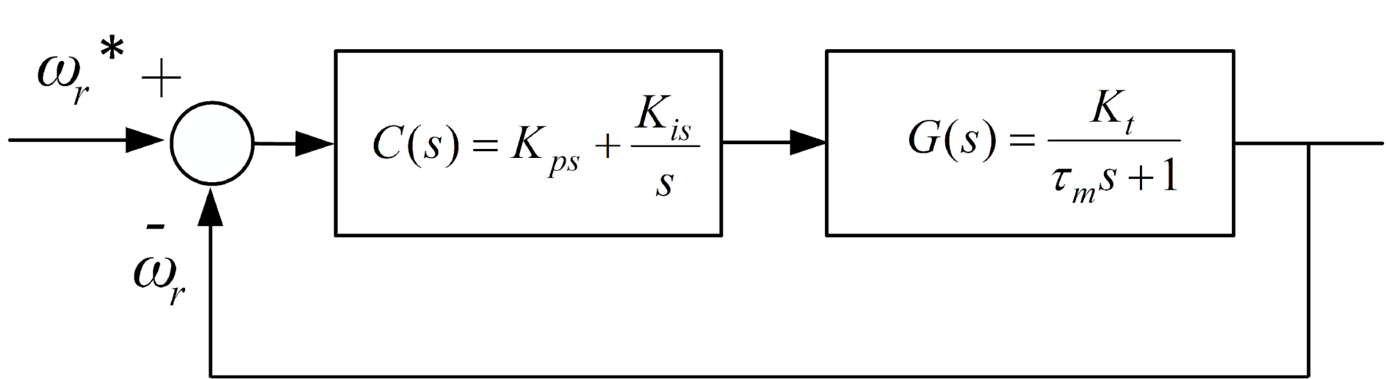
Figure 1. A block diagram of the speed control loop
- Designing NSTA_SOSM controller for the inner current loop control
The inner current loop control of FOC vector of IM drive using STA_SOSM controller. Stator current error is defined:
| 
| (11) |
The nonlinear improve slip surface according to the current components is chosen as follows:
| 
| (12) |
Where  We select the Lyapunov function:
| 
| (13) |
Differentiate both sides of equation (16) we get:
| 
| (14) |
To differentiate  , The current error differential function is chosen as follows:
| 
| (15) |
where:  and
and  are STASOSM control functions and defined:
| 
| (16) |
where:  with
with  . From Eq. (1), Eq. (14) to Eq. (16) we get
  and
and  virtual control functions:
| 
| (17) |
- Design of the Adaptive HOSM Disturbance Observer (OB)
The dynamics of the induction motor (IM) are commonly described in the synchronous rotating reference frame (d–q frame), under the field-oriented control (FOC) assumption, the electromagnetic torque  and the rotor speed ω are expressed as in Eq. (2). On the other hand, we also have:
| 
| (18) |
where: is the mechanical rotor speed, is the total moment of inertia of the motor and load, is the viscous friction coefficient,  is the external load torque. For control design, we can combine these equations. Let
  be the nominal torque constant. Equation (18) becomes:
| 
| (19) |
where:  is the q-axis stator current, which acts as the torque-producing current,
  is the number of pole pairs, ,
  are the mutual and rotor inductances, respectively,
  is the constant rotor flux linkage,
- Control Problem Formulation
The control objective is to design a controller for the q-axis current such that the rotor speed accurately tracks a desired reference speed , despite the presence of uncertainties and external disturbances.
Let us define the state variables for the speed control loop as  and
and  . The system dynamics can be expressed in a simplified state-space form suitable for controller design:
| 
| (20) |
where:  is the control input, (
 ) are the nominal system parameters,
  is the lumped disturbance, defined as:
| 
| (21) |
Here,  represents the effects of parameter variations (
 ) and unmodeled nonlinearities (e.g., friction, cogging). The core challenges are:
- To design a control law
 that is robust to the disturbance .
 - The disturbance is unknown and not directly measurable.
To address these challenges, we propose a composite control structure consisting of a main controller and a disturbance observer.
- Design of the Adaptive HOSM Disturbance Observer (OB)
This section presents the design of a novel direct adaptive higher-order sliding mode disturbance observer (OB). The observer's goal is to provide a high-precision, real-time estimation  of the lumped disturbance . The lumped disturbance is a continuously differentiable function, and its first time derivative is bounded by an unknown positive constant
  ,
,  . We design the observer to directly estimate . Let
  is an internal state variable of the observer. Its dynamics are defined as:
| 
| (22) |
where  is the estimated disturbance. A sliding variable s is defined using measurable and internal states:
| 
| (23) |
The derivative of the sliding variable s can be calculated by subtracting (22) from the time derivative of ω (which is  from Eq. (20)):
| 
| (24) |
| 
| (25) |
Let  be the disturbance estimation error. Equation (25) shows that the derivative of our computable sliding variable s is exactly equal to the estimation error
  . This elegant result forms the foundation of our direct observer.
- Adaptive super-twisting algorithm
To drive the estimation error to zero, we must first drive the sliding variable s to zero in finite time. We employ the Super-Twisting Algorithm (STA) to achieve this. The derivative of  is:
is:
| 
| (26) |
We design the law for to be an adaptive STA that counteracts the unknown perturbation  :
:
where  and
and  are the time-varying adaptive gains. From Eq. (19) and Eq. (21), the disturbance compensation current
  can be computed as:
| 
| (30) |
Accordingly, the total reference current is given by:
| 
| (31) |
- Adaptive laws and stability analysis
The key innovation is the design of the adaptive laws for  and
and  to eliminate the need for knowing the bound . We propose the "Increase-When-Needed" adaptive laws:
| 
| (32) |
| 
| (33) |
where:  is the sliding variable defined in (23),
  are positive design constants that determine the adaptation rates, ε₀ is a small positive constant defining the width of the boundary layer around the sliding surface
  .
.
It should be emphasized that the adaptive gains and are not constant values, but are dynamically updated online according to Eq. (32) and Eq. (33). In practice, at each time instant, the values of and are obtained by integrating their respective differential equations. When the sliding variable is larger than the threshold  , the gains increase proportionally to
  , which enhances the disturbance rejection capability. Conversely, when falls below , the gains decay exponentially, thus preventing unnecessarily large values and reducing chattering. This “increase-when-needed” mechanism eliminates the need for prior knowledge of the disturbance bound L, while ensuring finite-time convergence and robustness of the adaptive STA.
The stability of the complete adaptive observer system, described by Eq. (23) to Eq. (30), can be rigorously established using Lyapunov theory. The analysis shows that all error signals and adaptive gains remain Uniformly Ultimately Bounded (UUB). Consequently, the disturbance estimation error converges to a small, user-defined neighborhood of the origin within finite time. Furthermore, the estimated output , obtained through the integration in (27), provides a continuous and accurate approximation of the actual disturbance.
- RESULTS AND DISCUSS
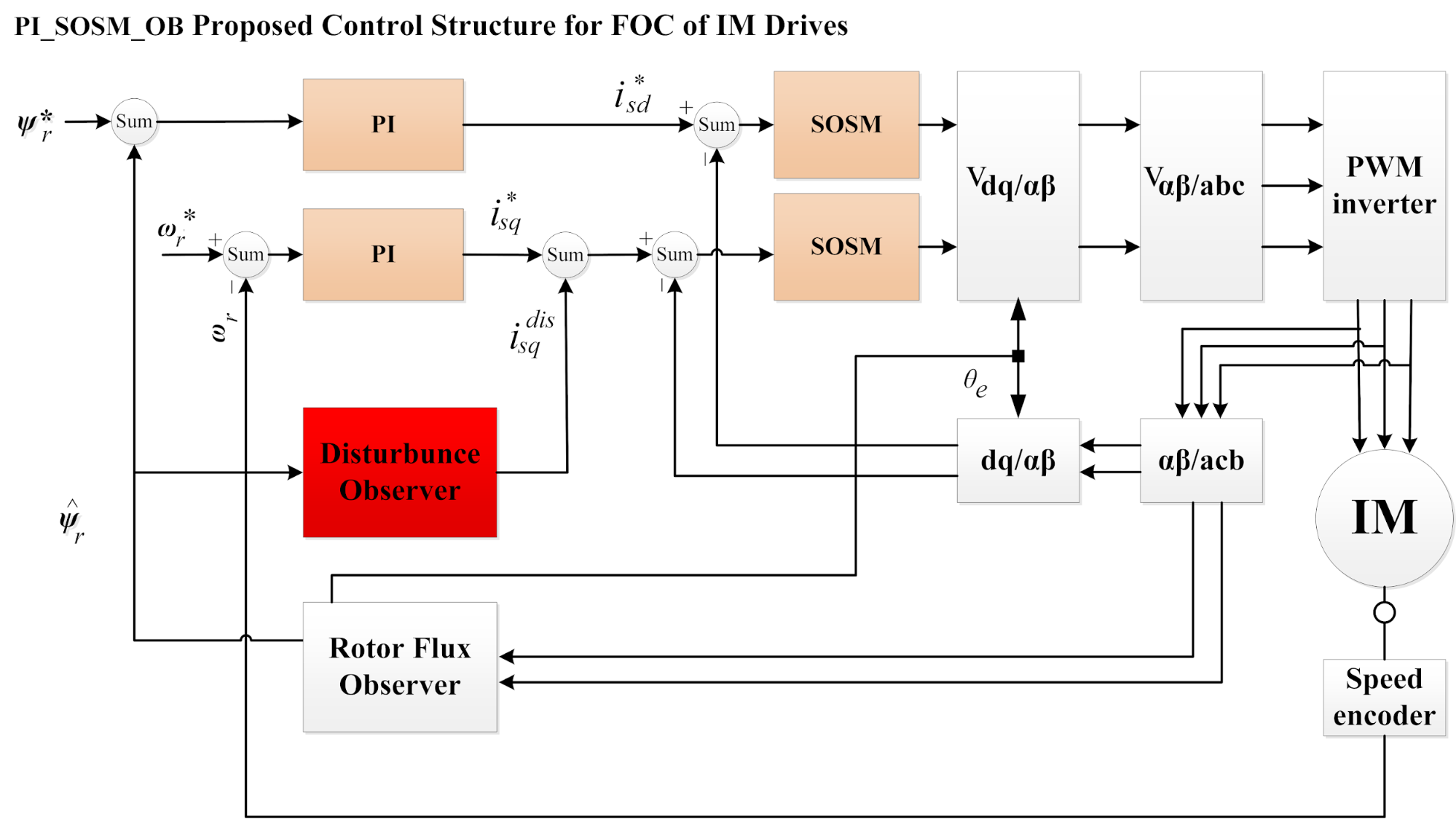
To validate the effectiveness and superiority of the proposed control strategy, comprehensive simulations are conducted in the MATLAB/Simulink environment can be seen in Figure 2. The parameters of the 1.5kW induction motor used in the simulation are: 400V, 50 Hz, 2 pole, 2950 rpm. Rs = 1.97Ω, Rr = 1.96Ω, Ls = 0.0154 H, Lr = 0.0154 H, Lm = 0.3585H, Ji = 0.00242 kg.m2.
Figure 2. The vector control of IM drive using PI SOSM OB control strategy
- Tracking Performance and Load Disturbance Rejection
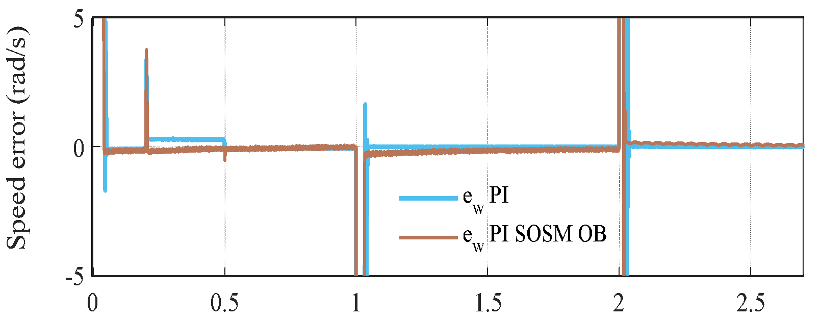
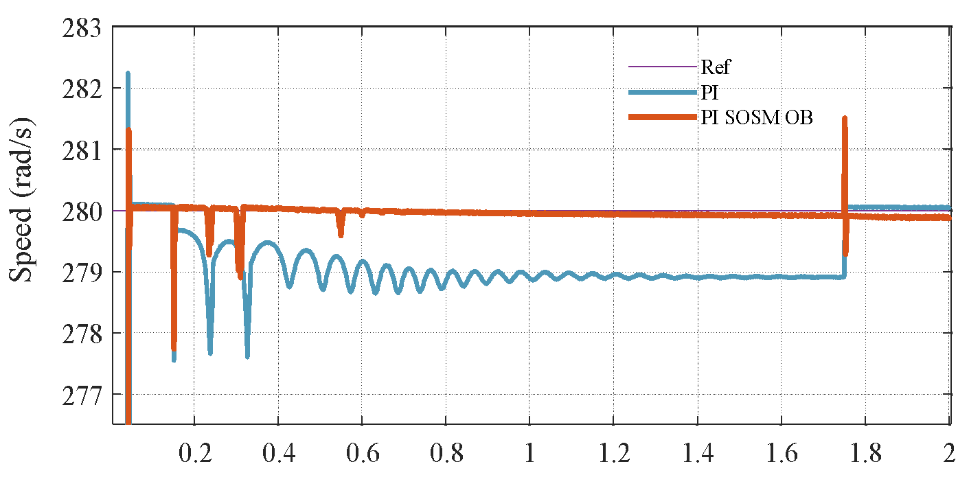
The controllers are assessed under a step load torque of  Nm, which is applied at
  s and removed at
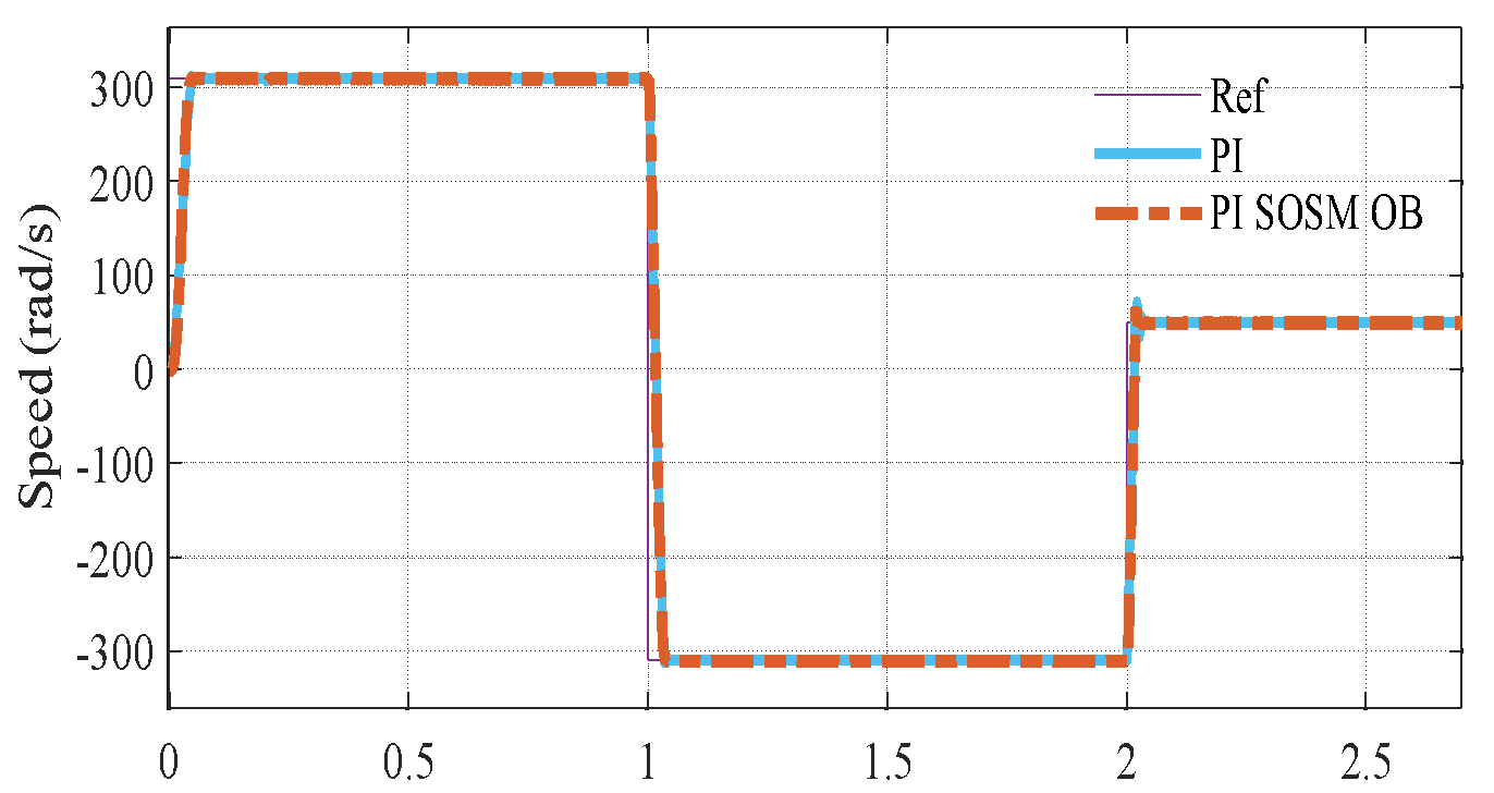
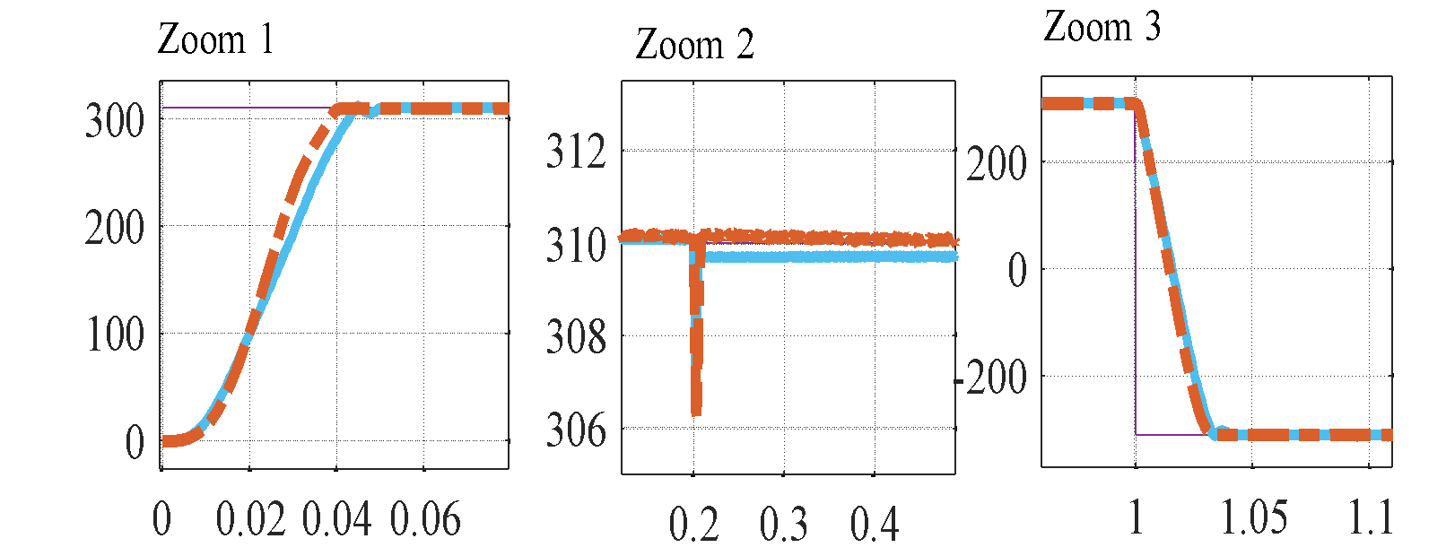
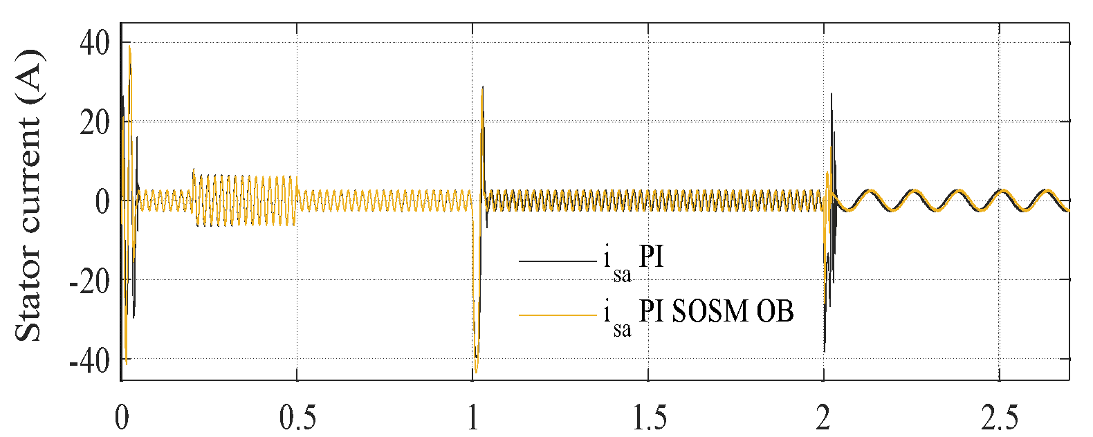
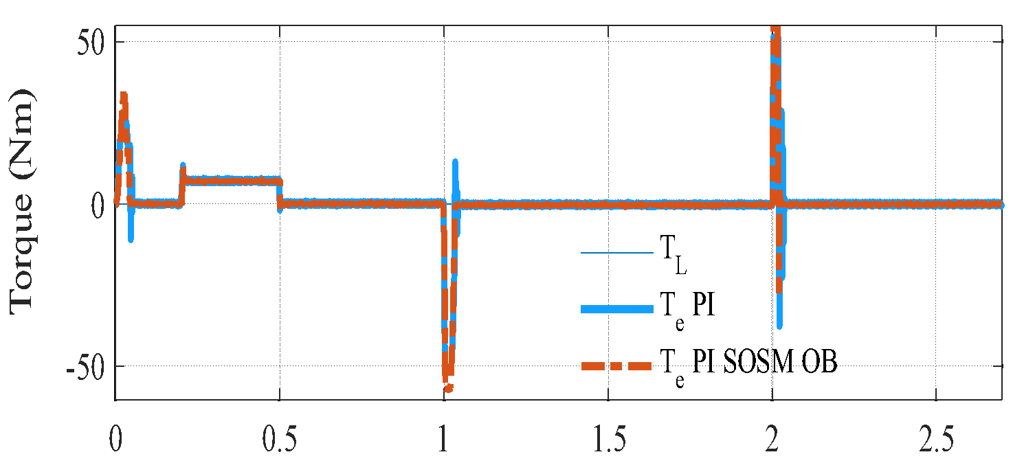
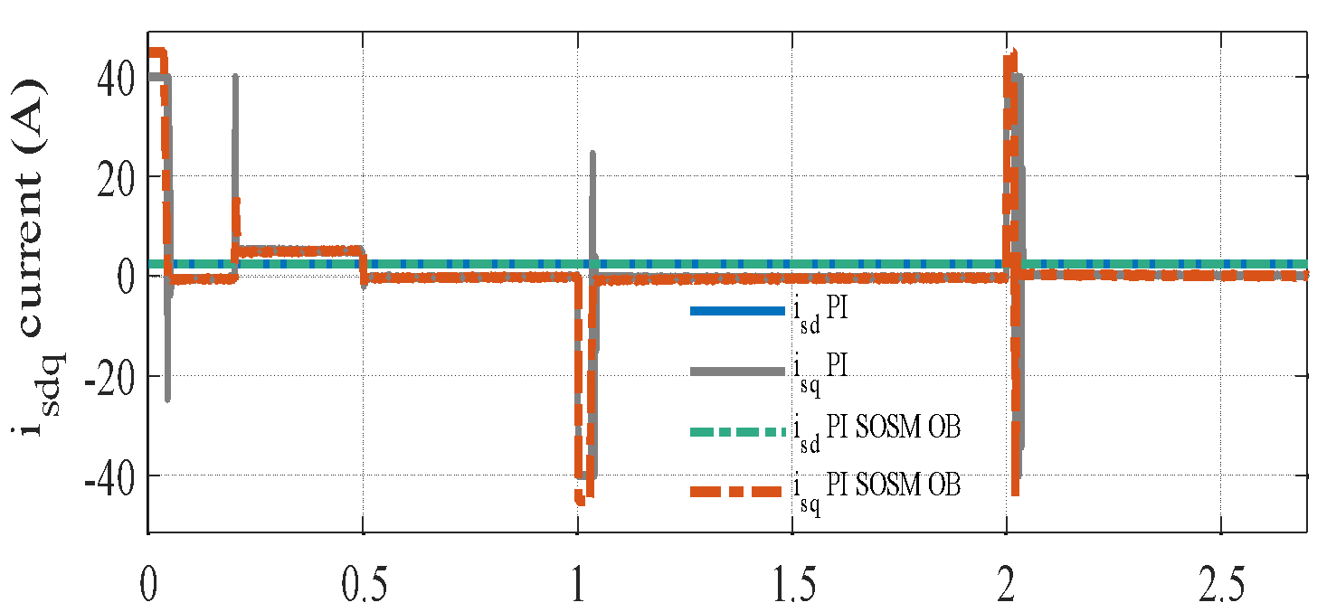
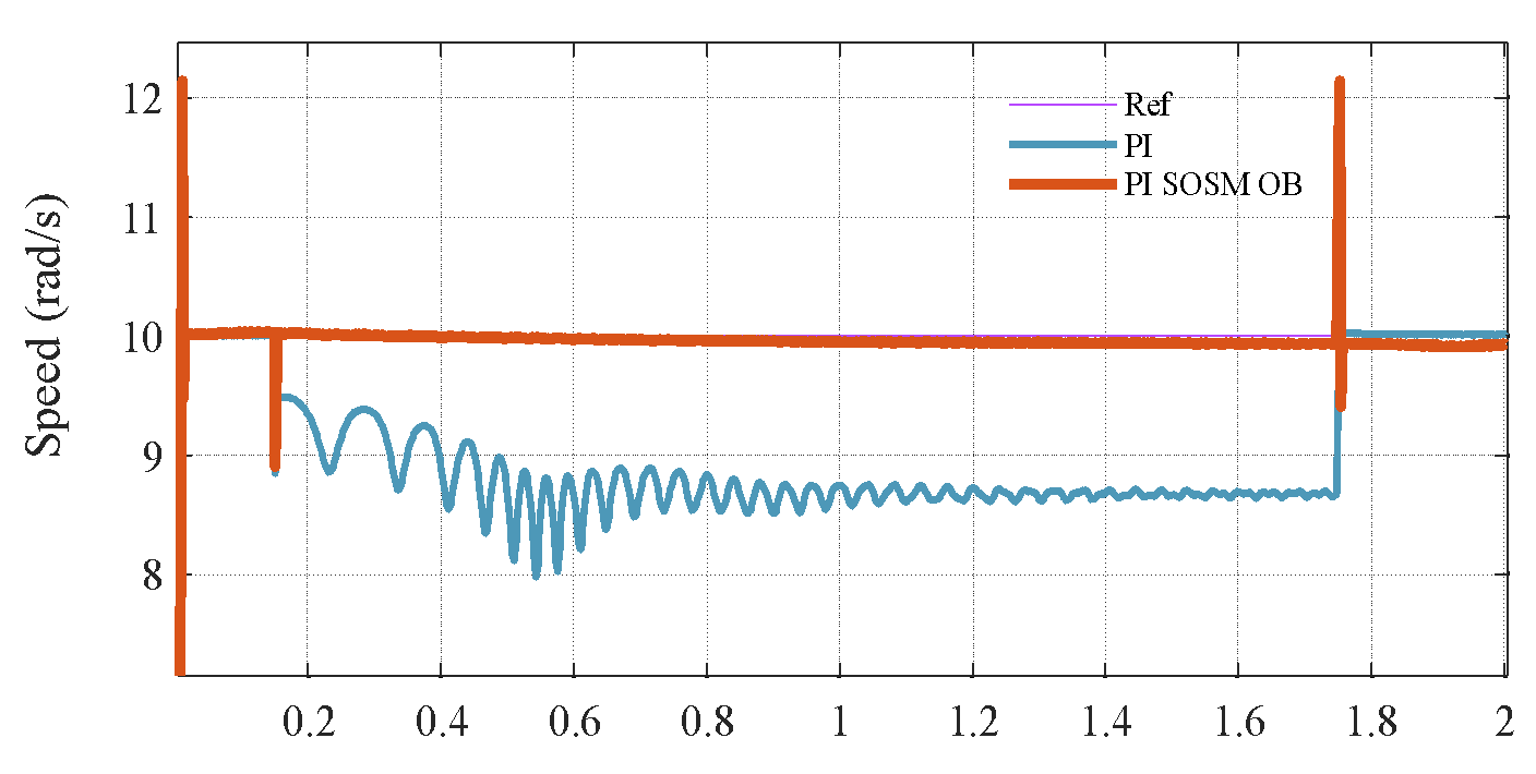
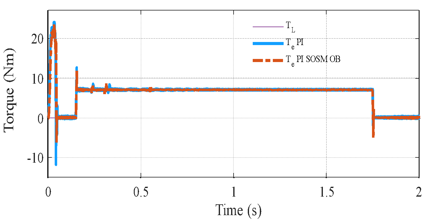
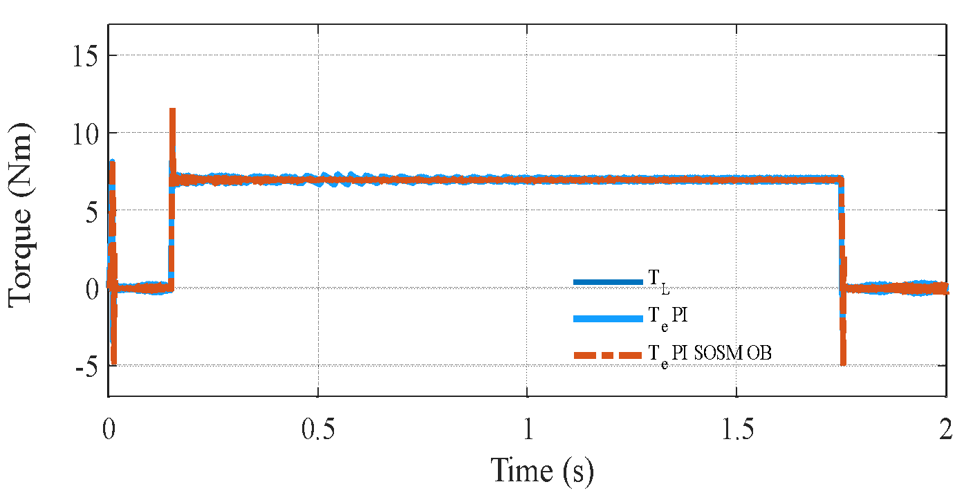
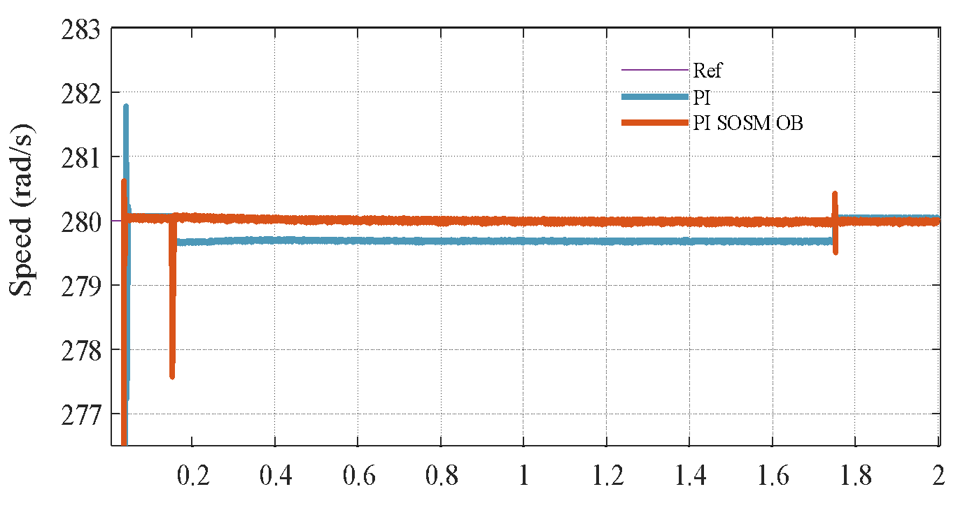
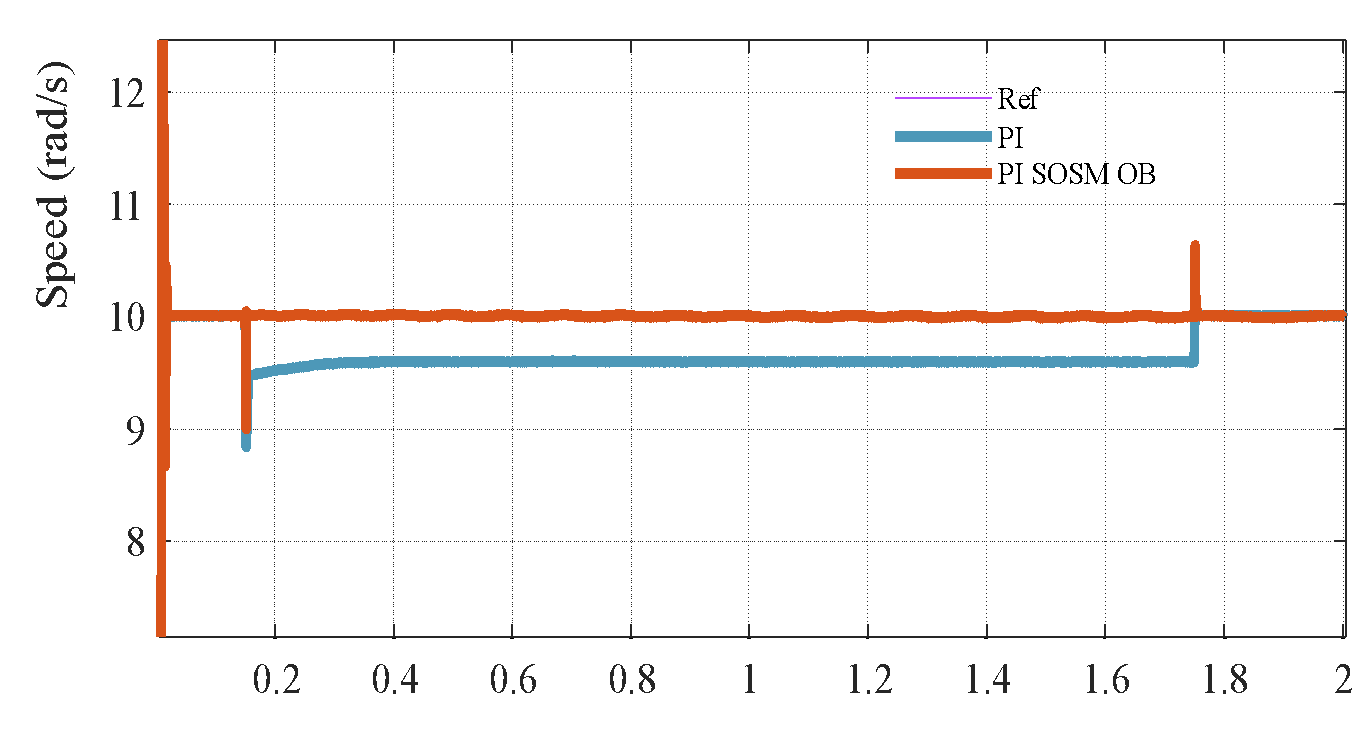
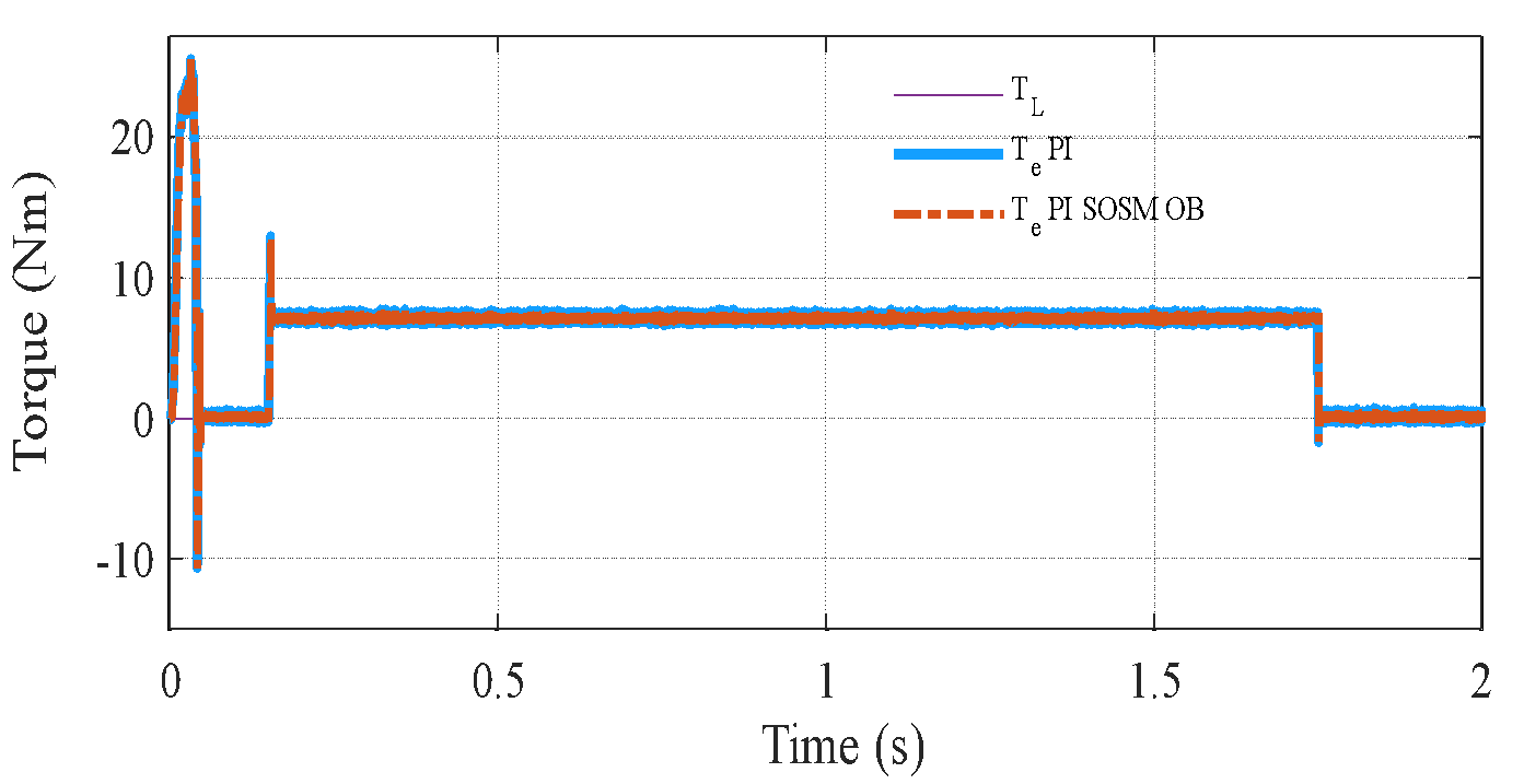
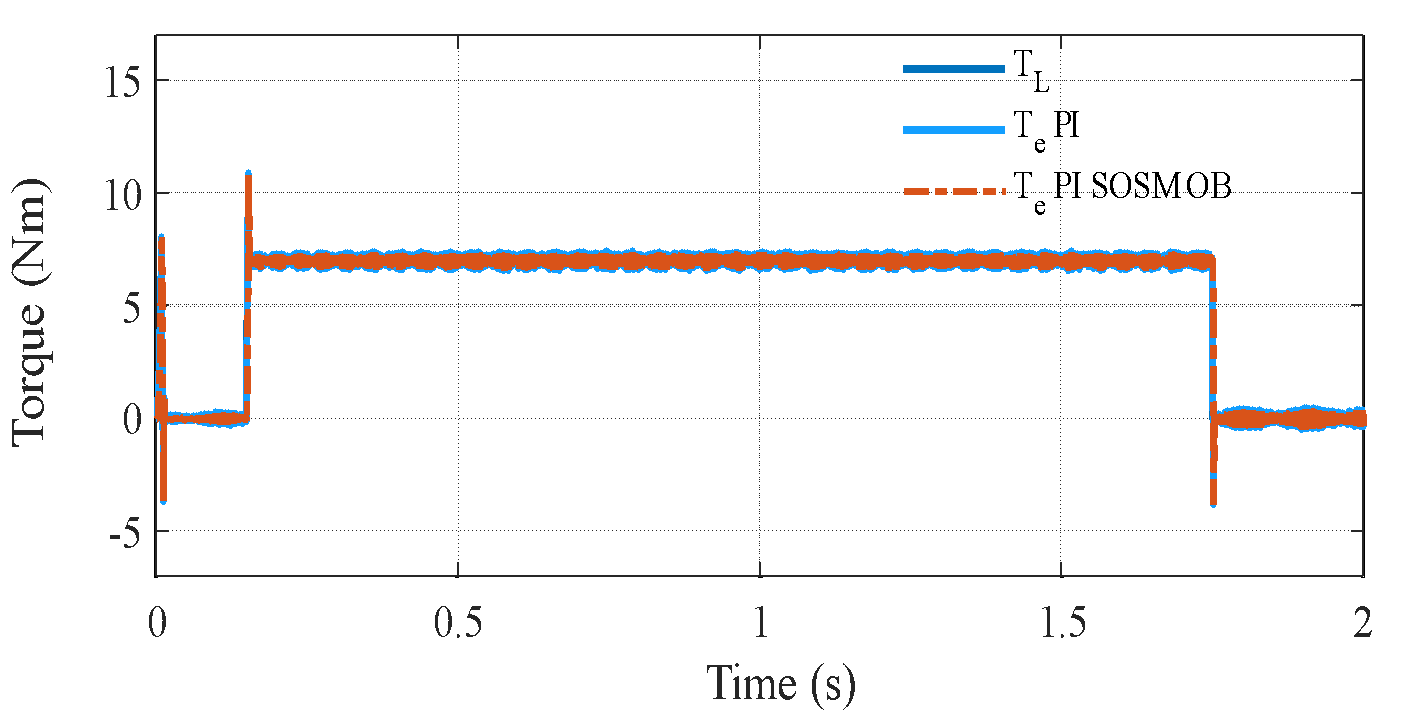
  s, while the rotor speed is regulated at a constant value of 310 rad/s throughout the experimental evaluation. Figure 3(a) to Figure 3(c) illustrate the corresponding speed tracking performance. Although both controllers successfully track the reference trajectory, their accuracy varies considerably, as evidenced by the tracking errors in Figure 3(b) and Figure 3 (c). The proposed PI–SOSM–OB control strategy demonstrates superior performance by maintaining the smallest tracking error, particularly during dynamic transients such as acceleration and speed reversal. Conversely, the conventional PI controller shows more pronounced deviations, thereby indicating reduced tracking accuracy. Figure 3(b) illustrates the disturbance rejection performance. The main advantage of the proposed method is clearly highlighted in this figure. As shown in Figure 3(b) to Figure 3(d), when a sudden load torque of 7 Nm is applied, both PI and PI–SOSM–OB control strategies experience a speed drop of about 58 rpm (19.3%), but the PI controller exhibits slower recovery and larger steady-state error. Figure 3(d) further confirms that the proposed system achieves a rapid and highly accurate torque response. . In addition, Figure 3(e) and Figure 3(f) illustrate the control effort (
 ) and the stator current (
 ) for the two strategies, revealing that the PI–SOSM–OB approach provides a more decisive and faster current response, thereby enhancing disturbance rejection capability.
|
|
a) Speed response for two controller strategy | b) Zoom speed response |
| 
|
c) Speed tracking error | d) Stator current for two controllers |
| 
|
e) Torque response | f) current for two controllers |
Figure 3. Comparative tracking and disturbance rejection and observer performance
- Robustness Test against Parameter Uncertainty
The simulation is conducted with a 100% increase in the rotor resistor ( ) of IM, while all controller parameters are kept unchanged. Figure 4 illustrates the system performance under significant parameter uncertainty. When the PI controller is tuned based on the nominal value of , its performance degrades, showing noticeable overshoot and oscillations. In contrast, the proposed control strategy preserves excellent tracking accuracy and exhibits only minimal oscillatory behavior. This robustness arises because the variation in is modeled as part of the lumped disturbance , which is effectively estimated and compensated by the PI–SOSM–OB scheme. These results confirm the superior disturbance rejection and robustness of the proposed method. To further investigate the robustness of the proposed PI–SOSM–Observer control structure, a critical test is performed under significant variation of the total moment of inertia , which represents both the motor and the mechanical load. In practical applications such as electric vehicles, industrial hoists, or robotic arms, load inertia can change dynamically due to gear shifts, variable payloads, or external couplings. Therefore, it is crucial for the control system to maintain stability and tracking performance under such conditions.
Figure 5 illustrates the system response when the total moment of inertia is doubled, while all control gains and parameters remain unchanged. This variation severely affects the mechanical time constant  and alters the system's dynamics, potentially degrading performance or even destabilizing the system if not properly handled. From Figure 5(a) and Figure 5(b), it can be clearly observed that the conventional PI controller exhibits increased overshoot, slower rise time, and extended settling time under the increased inertia. This degradation results from the fact that PI gains were tuned based on nominal , and the closed-loop poles shift due to the change in mechanical dynamics. Specifically, the mechanical subsystem responds more sluggishly, leading to poor speed tracking and larger steady-state deviations during transient events. In contrast, the proposed PI–SOSM–Observer strategy maintains excellent dynamic performance despite the change in . The system rapidly compensates for the slower mechanical dynamics through the adaptive feedforward disturbance compensation mechanism. The disturbance observer effectively treats the mismatch introduced by
  as part of the disturbance , and provides a real-time correction current that counteracts the undesired effect. The results demonstrate that the adaptive observer not only compensates for unknown load torque disturbances but also inherently addresses parametric uncertainties associated with system inertia. In addition, the SOSM current controller enhances overall robustness by guaranteeing accurate current tracking while eliminating chattering, even when the system response becomes sluggish due to increased inertia. As illustrated in Figure 5, the proposed hybrid control framework consistently maintains reliable performance under variations of the moment of inertia. This robustness is particularly valuable for practical applications operating under unpredictable load conditions, where preserving dynamic performance is crucial to ensuring both safety and efficiency.
| 
|
| 
|
a) Speed and torque response at high speed | b) Speed and torque response at high speed |
Figure 4. Speed response under variation
| 
|
| 
|
a) Speed and torque response at high speed | b) Speed and torque response at high speed |
Figure 5. Speed response under variation
- CONCLUSION
This paper has proposed a robust hybrid control strategy for induction motor drives, integrating a conventional PI controller for the speed loop, a Second-Order Sliding Mode (SOSM) current controller based on the Super-Twisting Algorithm, and a nonlinear disturbance observer for real-time disturbance compensation. The observer estimates the lumped disturbance and feeds it forward into the torque-producing current reference, thereby enhancing disturbance rejection capability. The key findings of this study are developed a novel PI–SOSM–OB hybrid control structure enhances robustness and dynamic performance while while maintaining simplicity and ease of practical implementation. This control scheme ensures effective disturbance rejection and robustness against parameter variations and chattering in current control is effectively mitigated while maintaining closed-loop stability. Limitations: The present study is restricted to simulation-based validation without experimental verification. Future Work: Future research will focus on experimental implementation, application to electric vehicle drives and multi-motor systems, and the development of fault-tolerant and adaptive extensions.
Author Contribution
All authors contributed equally to the main contributor to this paper. All authors read and approved the final paper.
Funding
This research received no external funding.
Conflicts of Interest
The authors declare no conflict of interest.
REFERENCES
- M. L. De Klerk and A. K. Saha, "A Comprehensive Review of Advanced Traction Motor Control Techniques Suitable for Electric Vehicle Applications," in IEEE Access, vol. 9, pp. 125080-125108, 2021, https://doi.org/10.1109/ACCESS.2021.3110736.
- I. Husain et al., "Electric Drive Technology Trends, Challenges, and Opportunities for Future Electric Vehicles," in Proceedings of the IEEE, vol. 109, no. 6, pp. 1039-1059, June 2021, https://doi.org/10.1109/JPROC.2020.3046112.
- Z. Yu and J. Long, “Review on advanced model predictive control technologies for high-power converters and industrial drives,” Electronics, vol. 13, no. 24, p. 4969. 2024, https://doi.org/10.3390/electronics13244969.
- J. M. Tabora et al., “Exploring the Effects of Voltage Variation and Load on the Electrical and Thermal Performance of Permanent-Magnet Synchronous Motors,” Energies, vol. 17, no. 1, p. 8, 2023, https://doi.org/10.3390/en17010008.
- B. Schiffer and L. Janson, “Foundations of safe online reinforcement learning in the linear quadratic regulator: Generalized baselines,” arXiv preprint arXiv:2410.21081, 2024, https://doi.org/10.48550/arXiv.2410.21081.
- M. Azab, A Review of Recent Trends in High-Efficiency Induction Motor Drives, Vehicles, vol. 7, no.1, p.15, 2025, https://doi.org/10.3390/vehicles7010015.
- H. J Abu-Rub, A. Iqbal, and J. Guzinski. High performance control of AC drives with Matlab/Simulink. John Wiley & Sons. 2021. https://books.google.co.id/books?hl=id&lr=&id=ndQnEAAAQBAJ.
- A El-Shahat. Induction Motors-Recent Advances, New Perspectives and Applications: Recent Advances, New Perspectives and Applications. 2023. https://books.google.co.id/books?hl=id&lr=&id=EWIHEQAAQBAJ.
- I. Djelamda and I. Bouchareb, “Field-oriented control based on adaptive neuro-fuzzy inference system for PMSM dedicated to electric vehicle,” Bulletin of Electrical Engineering and Informatics, vol. 11, no. 4, pp. 1892–1901, 2022, https://doi.org/10.11591/eei.v11i4.3818.
- N.T. Pham, “Sensorless speed control of SPIM using BS_PCH novel control structure and NNSM_SC MRAS speed observer,” J. Intell. Fuzzy Syst, vol. 39, no.3, 2020, https://doi.org/10.3233/JIFS-190540.
- A. Chantoufi et al., "Direct Torque Control-Based Backstepping Speed Controller of Doubly Fed Induction Motors in Electric Vehicles: Experimental Validation," in IEEE Access, vol. 12, pp. 139758-139772, 2024, https://doi.org/10.1109/ACCESS.2024.3462821.
- K. Rahman et al., "Field-Oriented Control of Five-Phase Induction Motor Fed From Space Vector Modulated Matrix Converter," in IEEE Access, vol. 10, pp. 17996-18007, 2022, https://doi.org/10.1109/ACCESS.2022.3142014.
- I. G. Prieto, M. J. Duran, P. Garcia-Entrambasaguas and M. Bermudez, "Field-Oriented Control of Multiphase Drives With Passive Fault Tolerance," IEEE Trans. Ind. Electron, vol. 67, no. 9, pp. 7228-7238, 2020, https://doi.org/10.1109/TIE.2019.2944056.
- N.T. Pham, "An Improved BS_NAHOSM Hybrid Control Strategy for FOC of Dual Star Induction Motor Drives", Period. Polytech. Electr. Eng. Comput. Sci., 2025. https://doi.org/10.3311/PPee.37384.
- M. Furmanik, L. Gorel, D. Konvičný, and P. Rafajdus, P. “Comparative study and overview of field-oriented control techniques for six-phase PMSMs,” Applied Sciences, vol. 11, no. 17, p. 7841, 2021, https://doi.org/10.3390/app11177841.
- I. M. Mehedi, N. Saad, M. A. Magzoub, U. M. Al-Saggaf and A. H. Milyani, "Simulation Analysis and Experimental Evaluation of Improved Field-Oriented Controlled Induction Motors Incorporating Intelligent Controllers," in IEEE Access, vol. 10, pp. 18380-18394, 2022, https://doi.org/10.1109/ACCESS.2022.3150360.
- M. M. Elkholy, M. M. Algendy, and E. A. El-Hay, “Modern Control Techniques and Operational Challenges in Permanent Magnet Synchronous Motors: A Comprehensive Review,” Automation, vol. 6, no. 4, p. 49, 2025, https://doi.org/10.3390/automation6040049.
- Q. Xue, X. Zhang, T. Teng, J. Zhang, Z. Feng, and Q. Lv, “A comprehensive review on classification, energy management strategy, and control algorithm for hybrid electric vehicles,” Energies, vol. 13, no. 20, p. 5355, 2020, https://doi.org/10.3390/en13205355.
- S. Nadweh, O. Khaddam, G. Hayek, B. Atieh, and H. H. Alhelou, “Optimization of P& PI controller parameters for variable speed drive systems using a flower pollination algorithm,” Heliyon, vol. 6, no. 8, 2020, https://doi.org/10.1016/j.heliyon.2020.e04648.
- S. Abd-Elhaleem, W. Shoeib and A. A. Sobaih, "Improved Power Management Under Uncertain Driving Conditions for Plug-In Hybrid Electric Vehicles via Intelligent Controller," in IEEE Transactions on Intelligent Transportation Systems, vol. 24, no. 12, pp. 13698-13712, Dec. 2023, https://doi.org/10.1109/TITS.2023.3308509.
- N.T. Pham, “Design of Novel STASOSM Controller for FOC Control of Dual Star Induction Motor Drives,” Int. J. Robot. Control Syst., vol. 4, no. 3, pp. 1059-1074, 2024, https://doi.org/10.31763/ijrcs.v4i3.1443.
- R. S. Kumar, et al., “A combined HT and ANN based early broken bar fault diagnosis approach for IFOC fed induction motor drive,” Alexandria Engineering Journal, vol. 66, pp. 15–30, 2023, https://doi.org/10.1016/j.aej.2022.12.010.
- G. K. Alitasb, “Integer PI, fractional PI and fractional PI data trained ANFIS speed controllers for indirect field oriented control of induction motor,” Heliyon, vol. 10, no. 18, 2024, https://doi.org/10.1016/j.heliyon.2024.e37822.
- I. M. Mehedi, N. Saad, M. A. Magzoub, U. M. Al-Saggaf and A. H. Milyani, "Simulation Analysis and Experimental Evaluation of Improved Field-Oriented Controlled Induction Motors Incorporating Intelligent Controllers," in IEEE Access, vol. 10, pp. 18380-18394, 2022, https://doi.org/10.1109/ACCESS.2022.3150360.
- N. T. Pham, “Novel Hybrid SM Strategy Based on Speed Control and Disturbances Rejection for High Performance DSIM Drives,” Journal of Robotics and Control (JRC), vol. 6, no. 2, pp. 995-1006, 2025, https://doi.org/10.18196/jrc.v6i2.24599.
- P. T. M. Sahridayan and R. Gopal,“Modeling and analysis of field-oriented control based permanent magnet synchronous motor drive system using fuzzy logic controller with speed response improvement,” Int. J. Electr. Comput. Eng. (IJECE), vol. 12, no. 6, pp. 6010–6021, 2022, https://doi.org/10.11591/ijece.v12i6.pp6010-6021.
- M. Aktas, K. Awaili, M. Ehsani, and A. Arisoy, “Direct torque control versus indirect field-oriented control of induction motors for electric vehicle applications,” Engineering Science and Technology, an International Journal, vol. 23, no. 5, pp. 1134-1143, 2020, https://doi.org/10.1016/j.jestch.2020.04.002.
- L. Wu, J. Liu, S. Vazquez and S. K. Mazumder, "Sliding Mode Control in Power Converters and Drives: A Review," in IEEE/CAA Journal of Automatica Sinica, vol. 9, no. 3, pp. 392-406, 2022, https://doi.org/10.1109/JAS.2021.1004380.
- C. A. Martínez‐Fuentes, U. Pérez‐Ventura, and L. Fridman, “Chattering analysis for Lipschitz continuous sliding‐mode controllers,” International journal of robust and nonlinear control, vol. 31, no. 9, pp. 3779-3794, 2021, https://doi.org/10.1002/rnc.5239.
- B. Zhang, X.n Tang, “High-performance state feedback controller for permanent magnet synchronous motor,” ISA Transactions, vol. 118, pp.144-158, 2021, https://doi.org/10.1016/j.isatra.2021.02.009.
- M. Kuczmann and K. Horváth, "Design of Feedback Linearization Controllers for Induction Motor Drives by using Stator Reference Frame Models," 2021 IEEE 19th International Power Electronics and Motion Control Conference (PEMC), pp. 766-773, 2021, https://doi.org/10.1109/PEMC48073.2021.9432503.
- M. Sellah, A. Kouzou, M. M. Rezaoui, R. Kennel và M. Abdelrahem, “Improved DTC-SVM based on input-output feedback linearization technique applied on DOEWIM powered by two dual indirect matrix converters,” Energies, vol. 14, no. 18, p. 5625, 2021, https://doi.org/10.3390/en14185625.
- A. Senhaji, M. Abdelouhab, A. Attar, A. Amri và J. Bouchnaif, “Input-Output feedback linearization control for SM-PMSM,” in E3S Web of Conferences, ICEGC 2023, vol. 00062, pp. 1–6, 2023, https://doi.org/10.1051/e3sconf/202346900062.
- H. Li, R. Zhang, P. Shi, Y. Mei, K. Zheng, and T. Qiu, “Sensorless control of a PMSM based on an RBF neural network-optimized ADRC and SGHCKF-STF algorithm. Measurement and Control, vol. 57, no. 3, pp. 266-279, 2024, https://doi.org/10.1177/00202940231195908.
- Y. Su et al., “Backstepping control of a bearingless induction motor based on a linear extended state observer,” Electr Eng, vol. 105, pp. 4569–4579, 2023, https://doi.org/10.1007/s00202-023-01958-5.
- L. Yi et al., “Intelligent detection of stator and rotor faults of induction motor based on improved backstepping sliding mode observer” Int. J. Dynam. Control, vol. 11, pp. 666–679, 2023, https://doi.org/10.1007/s40435-022-01010-7.
- Y. Xu, B. Huang, and Y. Sun, "Adaptive RBF neural network-based control for uncertain nonlinear systems," Automatica, vol. 158, pp. 111234, 2023. https://doi.org/10.1016/j.automatica.2023.111234.
- C. Melkia, M. Attia, R. Daouadi, and K. Rais, “Improved PMSM Speed Control Using Backstepping: Stability and Performance Analysis,” Journal Européen des Systèmes Automatisés, vol. 58, pp. 383-392, 2025, https://doi.org/10.18280/jesa.580219.
- H. Jie, G. Zheng, J. Zou, X. Xin and L. Guo, "Adaptive Decoupling Control Using Radial Basis Function Neural Network for Permanent Magnet Synchronous Motor Considering Uncertain and Time-Varying Parameters," in IEEE Access, vol. 8, pp. 112323-112332, 2020, https://doi.org/10.1109/ACCESS.2020.2993648.
- D. Brahim, M. Bendjebbar, and S. Lachtar, “Improvement of adaptive fuzzy control to adjust speed for a doubly fed induction motor drive (DFIM),” International Journal of Power Electronics and Drive System, vol. 11, no. 1, pp. 496–504, 2020, https://doi.org/10.11591/ijpeds.v11.i1.pp496-504.
- A. H. Ahmed, A. S. Yahya, and A. J. Ali, “Speed Control for Linear Induction Motor Based on Intelligent PI-Fuzzy Logic,” Journal of Robotics and Control (JRC), vol. 5, no. 5, 2024, https://doi.org/10.18196/jrc.v5i5.22203.
- Saidi, F. Naceri, L. Youb, M. Cernat, L. Guasch Pesquer, "Two Types of Fuzzy Logic Controllers for the Speed Control of the Doubly-Fed Induction Machine," Advances in Electrical and Computer Engineering, vol. 20, no. 3, pp. 65-74, 2020, https://doi.org/10.4316/AECE.2020.03008.
- W. Feng, J. Bai, and J. Zhang, “Full-order adaptive observer for interior permanent-magnet synchronous motor based on novel fast super-twisting algorithm,” Measurement and Control, vol. 56, no. 1–2, pp. 93–113, 2023, https://doi.org/10.1177/00202940221122235.
- A. Dawood, B. M. Hasaneen, and A. M. Abdel-Aziz, “Design of an efficient neural network model for detection and classification of phase loss faults for three-phase induction motor,” Neural Comput & Applic, vol. 36, pp. 5827–5845, 2024, https://doi.org/10.1007/s00521-023-09387-y.
- A. Ammar, O. Belaroussi, A. Zemmit, H. Said, and N. Belmadani, “Super-Twisting MRAS Observer-Based Non-linear Direct Flux and Torque Control for Induction Motor Drives,” Power Electron. Drives, vol. 9, no. 2, pp. 55–66, 2024, https://doi.org/10.2478/pead-2024-0024.
- A. Nurettin and N. İnanç, "High-Performance Induction Motor Speed Control Using a Robust Hybrid Controller With a Supertwisting Sliding Mode Load Disturbance Observer," in IEEE Transactions on Industrial Electronics, vol. 70, no. 8, pp. 7743-7752, 2023, https://doi.org/10.1109/TIE.2022.3222625.
- L. Qu, W. Qiao and L. Qu, "Active-Disturbance-Rejection-Based Sliding-Mode Current Control for Permanent-Magnet Synchronous Motors," in IEEE Transactions on Power Electronics, vol. 36, no. 1, pp. 751-760, 2021, https://doi.org/10.1109/TPEL.2020.3003666.
- M. Hu, H. Ahn and K. You, "Speed Tracking of SPMSM via Super-Twisting Logarithmic Fast Terminal Sliding-Mode Control," in IEEE Access, vol. 11, pp. 91904-91912, 2023, https://doi.org/10.1109/ACCESS.2023.3308156.
- W. Wang, Y. Ye, X. Chen and Y. Yuan, "Adaptive High-Order Sliding-Mode Low-speed Control With RBF Neural Network Nonlinear Disturbance Observer for PMSM Drive System," in IEEE Transactions on Power Electronics, vol. 40, no. 8, pp. 10865-10876, 2025, https://doi.org/10.1109/TPEL.2025.3559890.
- C. Wei, J. Xu, Q. Chen, C. Song and W. Qiao, "Full-Order Sliding-Mode Current Control of Permanent Magnet Synchronous Generator With Disturbance Rejection," in IEEE Journal of Emerging and Selected Topics in Industrial Electronics, vol. 4, no. 1, pp. 128-136, 2023, https://doi.org/10.1109/JESTIE.2022.3192735.
- H. Ríos, R. Franco, A. F. de Loza and D. Efimov, "A High-Order Sliding-Mode Adaptive Observer for Uncertain Nonlinear Systems," in IEEE Transactions on Automatic Control, vol. 68, no. 1, pp. 408-415, 2023, https://doi.org/10.1109/TAC.2021.3139308.
- L. Xu, S. Zhuo, J. Liu, S. Jin, Y. Huangfu and F. Gao, "Advancement of Active Disturbance Rejection Control and Its Applications in Power Electronics," in IEEE Transactions on Industry Applications, vol. 60, no. 1, pp. 1680-1694, 2024, https://doi.org/10.1109/TIA.2023.3312653.
- T. H. Nguyen, T. T. Nguyen, V. Q. Nguyen, K. M. Le, H. N. Tran and J. W. Jeon, "An Adaptive Sliding-Mode Controller With a Modified Reduced-Order Proportional Integral Observer for Speed Regulation of a Permanent Magnet Synchronous Motor," in IEEE Transactions on Industrial Electronics, vol. 69, no. 7, pp. 7181-7191, 2022, https://doi.org/10.1109/TIE.2021.3102427.
- Y. He, Z. Cao, J. Mao, K. Liang and C. Zhang, "Adaptive Super-Twisting Sliding Mode Control With Disturbance Compensation for Speed Regulation of PMSM System," in IEEE Control Systems Letters, vol. 8, pp. 3410-3415, 2024, https://doi.org/10.1109/LCSYS.2025.3541167.
- T. Wang, B. Wang, Y. Yu and D. Xu, "High-Order Sliding-Mode Observer With Adaptive Gain for Sensorless Induction Motor Drives in the Wide-Speed Range," in IEEE Transactions on Industrial Electronics, vol. 70, no. 11, pp. 11055-11066, 2023, https://doi.org/10.1109/TIE.2022.3227272.
BIOGRAPHIES OF AUTHORS

| Thanh Tinh Pham was born in 2000, in Vietnam. He received his engineer’s degree in Electrical and Electronic Engineering from Ho Chi Minh City University of Industry in 2022 and subsequently worked for the Ho Chi Minh City Oil and Gas Single-Member Limited Liability Company. In 2023, he began pursuing the Master's program at Ho Chi Minh City University of Industry. His research interests include motor drives, multiphase motors, renewable energy, embedded systems, and intelligent control. He can be contacted at email: 22734111.tinh@student.iuh.edu.vn. |
|
|

| Ngoc Thuy Pham     is a lecturer in Department of Electrical Engineering Technology, Industrial University of Ho Chi Minh City (IUH), Ho Chi Minh, Viet Nam. She received the B.Sc. and M.Sc. degrees in Electrical Engineering from Thai Nguyen University of Technology in 1994 and Ho Chi Minh City University of Technology (HCMUT) in 2009, respectively. and Ph.D. degree in control engineering and automation from TE and Electrical Engineering from Ho Chi Minh City University of Transport, in 2020. Her current research interests include power electronics, AC motor drives, intelligent control, multiphase induction motor, sensorless control of multiphase induction motor drives, embedded system. She can be contacted at email: phamthuyngoc@iuh.edu.vn. is a lecturer in Department of Electrical Engineering Technology, Industrial University of Ho Chi Minh City (IUH), Ho Chi Minh, Viet Nam. She received the B.Sc. and M.Sc. degrees in Electrical Engineering from Thai Nguyen University of Technology in 1994 and Ho Chi Minh City University of Technology (HCMUT) in 2009, respectively. and Ph.D. degree in control engineering and automation from TE and Electrical Engineering from Ho Chi Minh City University of Transport, in 2020. Her current research interests include power electronics, AC motor drives, intelligent control, multiphase induction motor, sensorless control of multiphase induction motor drives, embedded system. She can be contacted at email: phamthuyngoc@iuh.edu.vn. |
Thanh Tinh Pham (A Hybrid PI–SOSM Control Strategy with Disturbance Observer for Enhanced Dynamic Response of IM Drives)