ISSN: 2685-9572 Buletin Ilmiah Sarjana Teknik Elektro
Vol. 8, No. 2, April 2026, pp. 585-597
Design and Optimization of Circularly Polarized Dual Band Patch Antenna Using Whale Optimization Algorithm for Wireless Communications
N. Nirmal Singh 1, K. Komathy Vanitha 2, M.S. Sumi 3, Jarin Joe Rini J 4, T. Geetha 5,
Sundar Ramakrishnan 6
1 Department of Electronics and Communication Engineering, DMI college of Engineering, Chennai, India.
2 Department of Electronics and Communication Engineering, CSI College of Engineering, Ketti- 643215, The Nilgiris, India
3 Department of Electronics and Communication Engineering, Rohini College of Engineering and Technology, Kanyakumari District, 629 401, India
4 Department of Electrical and Electronics Engineering, Dhanalakshmi Srinivasan College of Engineering, Coimbatore, 641105, India
5 Department of Mechatronics Engineering, Agni College of Technology, Chennai, India
6 Department of Biomedical Engineering, Dr.N.G.P. Institute of Technology, Coimbatore, Tamil Nadu 641048, India
ARTICLE INFORMATION |
| ABSTRACT |
Article History: Received 26 July 2025 Revised 04 October 2025 Accepted 11 May 2026 |
| 
In the realm of wireless communication systems, the demand for high-performance antennas proficient of accommodating numerous frequency bands whereas sustaining circular polarization has seen substantial growth. This work presents a unique approach for addressing this need. The antenna design begins with the incorporation of a patch structure, which, when properly configured, operates at 2.4GHZ and 5 GHz that corresponds to Wi-Fi bonds while simultaneously generating circular polarization. To optimize the antenna's performance, the Whale Optimization Algorithm (WOA) is employed. The WOA is a metaheuristic optimization approach enthused by the foraging behavior of humpback whales' feeding habits, known for its capability to proficiently explore complex solution spaces and find near-optimal configurations. This research emphasizes the importance of circular polarization in various wireless communication applications, comprising RFID systems, satellite communication, and GNSS receivers, among others. The utilization of dual bands ensures flexibility in accommodating multiple wireless standards within a single device. By leveraging the WOA, the antenna's parameters, such as dimensions and feeding techniques, are fine-tuned to maximize its circular polarization and impedance matching capabilities. This study's findings show how effective the suggested strategy is, showcasing a gain and return loss of 2.6353 dBi and -4.58 dB with radiation efficiency is 79.05 % at 2.4 GHZ and 74.83 % at 5 GHZ. Performance metrics, including gain, axial ratio, and impedance bandwidth, are rigorously evaluated, highlighting the antenna's suitability for contemporary wireless systems via wireless methods. Besides antenna design, this research offers plenty of benefits, as the integration of the WOA holds promise for enhancing the performance of other complex engineering systems. |
Keywords: Circularly Polarized Dual-Band Patch Antenna; Whale Optimization Algorithm; Radio Frequency Identification (RFID) and Global Navigation Satellite System (GNSS); Satellite Communication |
Corresponding Author: N. Nirmal Singh, Department of Electronics and Communication Engineering, DMI college of Engineering, Chennai, India. Email: nnirmalsingh@gmail.com |
This work is open access under a Creative Commons Attribution-Share Alike 4.0 
|
Document Citation: N. N. Singh, K. K. Vanitha, M. S. Sumi, J. J. R. J, T. Geetha, and S. Ramakrishnan, “Design and Optimization of Circularly Polarized Dual Band Patch Antenna Using Whale Optimization Algorithm for Wireless Communications,” Buletin Ilmiah Sarjana Teknik Elektro, vol. 8, no. 2, pp. 585-597, 2026, DOI: 10.12928/biste.v8i2.14340. |
- INTRODUCTION
Due to the rapid advancements in satellite and wireless communication, there is a tremendous need for antennas that are inexpensive, weight-less, compact, and low-profile that can maintain acceptable performance over multiple frequencies. In satellite communication, circularly polarised antennas are frequently employed because they maintain a steady state connection among sending and accepting antennas despite polarisation mismatch [1]. In contrast to linearly polarised antennas, circularly polarised radiation patterns enable data transfer to take place despite how the receiving and transmitting devices are positioned. It so happens since diffraction and scattering-induced depolarization of EM waves has no negative impact in circular polarization’s reception as much as it does for linear polarisation [2]. It can also be used to avoid multipath distortion and polarisation mismatch losses. Circularly polarised antennas of many types are explored, including monopoles, wide-slot antennas and crossed-dipole antennas. These antennas' high profiles, however, limit their applicability [3]-[6]. In comparison to the antennas discussed above, dual band circularly polarised antennas are an attractive candidate due to desirable characteristics [7] and easy conformability with integrated circuits and it simultaneously obtain benefits from dual band operation, which improves separation between reception and transmission and makes optimum use of the available frequency spectrum. In a single radiating structure, dual-band antennas have a dual-resonant behaviour. Dual-band patch antennas [8] could replace the need for two separate antennas when the system needs to operate at excessively far-distanced frequencies. These antennas have the unique ability to correspond with the incoming impedance at two distinct frequencies concurrently utilizing a single feed setup.
In recent years, ideas for dual-frequency circularly polarized antennas have gained popularity. A dual-band omnidirectional circularly polarized (CP) antenna is described in the article [9]. It typically needs two vertically and horizontally polarized, orthogonal, omnidirectional linearly polarized pulses. These 2 modes need to be excited with a phase difference of 90° in order to produce CP waves. Although the impedance bandwidth is rather low, it operates over two frequency ranges, can significantly enhance the antenna's application. However, the frequency ratio between both resonating phases stays constant. To address this issue, reserved dual-band dual polarised antenna are introduced [10][11]. Dual linear polarization [12] can increase channel capacity and mitigate multipath fading. Furthermore, to sustain polarisation purity and appropriate bandwidths in 2 frequencies, a dual-band polarized antenna [13][14] necessitates cautious mode excitation. Over the years, a lot of research for compact single-feed multi-band circularly polarised antennas have been conducted. In, stacked patch antennas with dual-band operation were employed. Dual-band circular polarisation is done by using two patches that differ in size and structure. However, because to the two-layer structure, the profiles of these two antennas remain large. In [15][16], CP antennas with hybrid feed networks were examined, however the structure complexity was found to be quite significant. To sort these problems in existing approaches, dual band circularly polarized patch antenna has been introduced in this work. Analogizing with existing circular polarization antenna design [17][18], the presented antenna has best features such as dual-band radiation properties, enhanced gain, radiation efficiency, a reduced size, light weight and a simple construction.
To optimize the antenna’s performance, various swarm intelligence algorithms [19] have been implemented. The optimisation impact is weak for traditional intelligent algorithms since they cannot simultaneously optimise many parameters [20][21]. The antenna design employs a swarm intelligence optimisation technique to address this issue. The popularity of swarm intelligence-based algorithms in the optimisation sector has grown over time. The WOA [22] is a well-known meta-heuristics nature influenced swarm intelligence-based method. It is extensively adopted to resolve issues related to optimization as it is incredibly simple and has the knack of delivering the best possible results efficiently. When comparing the most well-known and widely used optimisation techniques, the WOA technique excels at optimising the parameters.
Particle Swarm Optimization [23]-[25] is prone to get locked in local minima, which causes an early convergence and a weak exploitation in the latter stage. In comparison to other heuristic methods, Ant colony and cuckoo search optimization algorithm [26][27] converge more slowly, and the exact timing of convergence is unclear. Analogizing with these optimisation techniques, WOA achieves the global or nearly global optimum more quickly [28]. However, it has premature convergence in high-dimensional spaces and sensitive to parameter tuning.
- Research Gap
The conventional antennas often have better performance but they still have limitations such as gain, efficiency and bandwidth due to their size and fixed radiation pattern. Also, they operated in a narrow frequency range that provides reduced efficacy. Hence forth, these difficulties are solved by a proposed antenna.
- Background
It provides reliability and versatility over 2 distinct frequency bands. The CP develops the antenna insensitive to receiver orientation and diminishing signal loss from polarization mismatch, which is appropriate for wireless applications. The contribution of the developed work are as: i) Designing the antenna which is fully compatible with Wi-Fi bands ii) Leveraging the WOA to optimize the antenna parameters which is highly efficient to explore complex solution spaces and find near-optimal configurations. iii) To enhance the antenna parameters such as gain, directivity and return loss over conventional designs. iv) Incorporation of WOA allows the faster convergence and better global search capability. It is organized as: Section II will describe about the design and optimization of dual band circularly polarised patch antennas; section III will examine simulation results and antenna performance. Section IV will include the paper's conclusion.
- PROPOSED WORK
The CP dual band patch antenna is designed in this present work. In this proposed system, the patch structure, which is the foundation of the antenna design, allows it to operate at two different frequency bands while simultaneously producing circular polarisation. The WOA is used to enhance the antenna's performance. The WOA offers a metaheuristic optimisation technique inspired by the feeding behaviours of humpback whales, which is renowned for its ability to quickly explore large solution areas and identify close to ideal configurations.
- Antenna Design
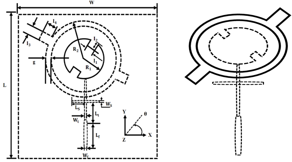
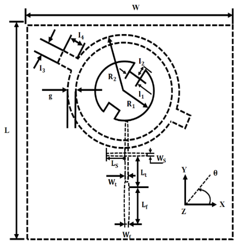
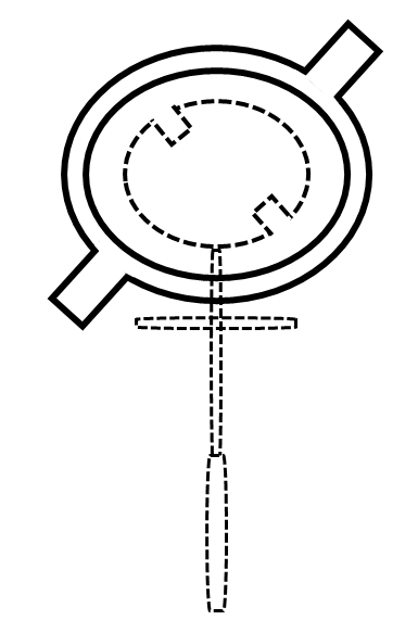
Figure 1(a) and Figure 1(b) show the schematic diagrams of the top patch’ circular patch with the ring slot of the ground plane of the provided antenna. The circular patch of the frontal top band is a kind of microstrip patch antenna that has a circular shape and is given to a coaxial cable or a microstrip line. The ring slot of the rear bottom band is a type of slot antenna that has a ring shape and is fed by a microstrip line. The patch and the slot are placed on different layers of the FR-4 substrate, which is a common material for printed circuit boards.
| 
|
(a) | (b) |
Figure 1. (a) Top patch (b) Bottom ground plane of the antenna
The patch antenna was intended to be built on FR-4 substrate where it’s dielectric constant  is 4.3 and thickness is 1.6 mm of the substrate affect the resonant frequency and the bandwidth;
  and
and  are the width and length. The radius
  and
and and the circular patch’ width is
  and the ring slot determine the radiating element’s shape and size. The larger the radius, the lower the resonant frequency. The larger the width, the broader the bandwidth. The substrate's breadth and length have an effect on the performance of antenna as well. Substrate should be large enough to avoid edge effects and radiation leakage. To create circular polarisation radiation over the upper and lower bands, two sets of notches are put into the circular patch as well as the ring slot. The resonant mode may be interrupted by these notches, which may also produce two orthogonal degenerate modes. The notches have lengths
  correspondingly. A phase shift of 90° for CP in a proposed antenna is attained by exciting 2 orthogonal modes with phase difference of 90° and identical amplitude. The circular patch in top layer and ring slot in bottom layer are electromagnetically coupled via a substrate. A coaxial feed excites a circular patch and a microstrip line offers coupling to the ring slot. By comprising an impedance matching circuit that links the radiator and the microstrip feeder, the impedance matching is improved. The branch impedance adapter is used for the higher radiator, while the quarter wavelength transformer is used for the lower radiator. Table 1 displays the antenna's precise specifications.
Table 1. Antenna’s optimized parameters
Parameter | Value (mm) |
| 120 |

| 0.5 |
| 15.0 |
| 160 |

| 23.0 |

| 3.1 |

| 2.0 |

| 23.0 |

| 29.0 |

| 12.5 |

| 3.0 |

| 6.5 |

| 2.5 |

| 9.0 |
| 2.0 |
- Design Procedure
Designing a developed antenna involves a systematic procedure to attain the preferred operating frequencies and polarization features. Firstly, the selection of a appropriate substrate with known dielectric constant  and thickness
  is crucial. The resonant frequencies for the two desired bands are determined based on the applications. For designing an antenna, some parameters such as resonant frequency, relative dielectric constant and thickness are to be known. The circular patch's radius can be calculated using,
| 
| (1) |
It relates the patch’s geometry to the desired resonant frequency.
Where
In general, the patch diameter ( ) is twice as big as the length and width. As a result, and are expressed by,
| 
| (2) |
| 
| (3) |
Both expressions (2) and (3) assures proper resonance at the target frequency and influences impedance and radiation characteristics. Resonant frequency: The resonant frequency  is calculated by using the formula given (4),
| 
| (4) |
Where, the subscript  refers to
  modes, c indicates the light’s speed in free space, denotes the dielectric constant and
  represents the wave number and is expressed by the given equation as follows,
| 
| (5) |
Where is the radius of the circular patch
| 
| (6) |
Where, the Effective dielectric constant is 
It is vital for accurate frequency estimation. For the patch antenna, the input impedance is provided by,
| 
| (7) |
It is vital for assuring proper impedance matching with the feed line.
Where,
And Effective loss tangent is given by,
| 
| (8) |
Equation (1) and equation (2) being approximations, it is determined that the suggested antenna's required properties are unsatisfactory. Hence, by leveraging the whale optimization technique, the antenna's parameters are fine-tuned to maximize its circular polarization and impedance matching capabilities.
- Whale Optimization Algorithm
The WOA is an algorithm that uses metadata draws inspiration from nature. It is based on how humpback whales hunt and interact with one another. Whales has the capacity to spot out the prey in the natural world and encircle them with precise movements. The ideal set of patch and slot characteristics that yields the lowest axial ratio and maximum gain at the intended dual bands indicates the prey in this antenna design (Figure 2). Every whale stands for a potential antenna design, which is modified as iterations go on to get closer to the arrangement that performs the best. The fitness function is,
| 
| (9) |
Where,
| 
| (10) |
The whale behavior in WOA (surrounding the prey during the optimization stage) is mathematically represented by the following equations:
| 
| (11) |
| 
| (12) |
Where G represents the current iteration,  and
and  denotes
  member of population and optimal solution present in
  dimension respectively,
  indicates the distance vector,
  are the dimension vector coefficients. An optimization problem's decision variable vector is referred to as the
  dimension. The vector coefficients are,
| 
| (13) |
| 
| (14) |
Where  represents the number belongs to [2,0] which progressively decreases in both the phases of the exploitation and exploration and
  stands for random number distributed uniformly.
The exploitation step of the optimization process is comparable to the mathematically modeled bubble-net behavior of humpback whales by WOA. This is done by fusing two different movement mechanisms: (a) circularly enclosing with a reducing radius and (b) updating location utilising a spiral trajectory. A spiral equation is used in the latter one to model humpback whales in order to imitate their helix-shaped movements. It is written as,
| 
| (15) |
Where  indicates the distant vector’s position between the and the optimal solution, constant value is represented by k and S is a random number distributed uniformly
  . As they travel in a spiraling motion and in a circle with a converging circumference in search of their prey, humpback whales simultaneously employ two different mechanisms.
| 
| (16) |
Where, b indicates  (the random value)
In addition, humpback whales hunt their target in an unpredictable manner. In the optimisation process, WOA’s exploration phase is given by:
| 
| (17) |
| 
| (18) |
where  is a member of the population chosen at random to be followed by member
  with
with 
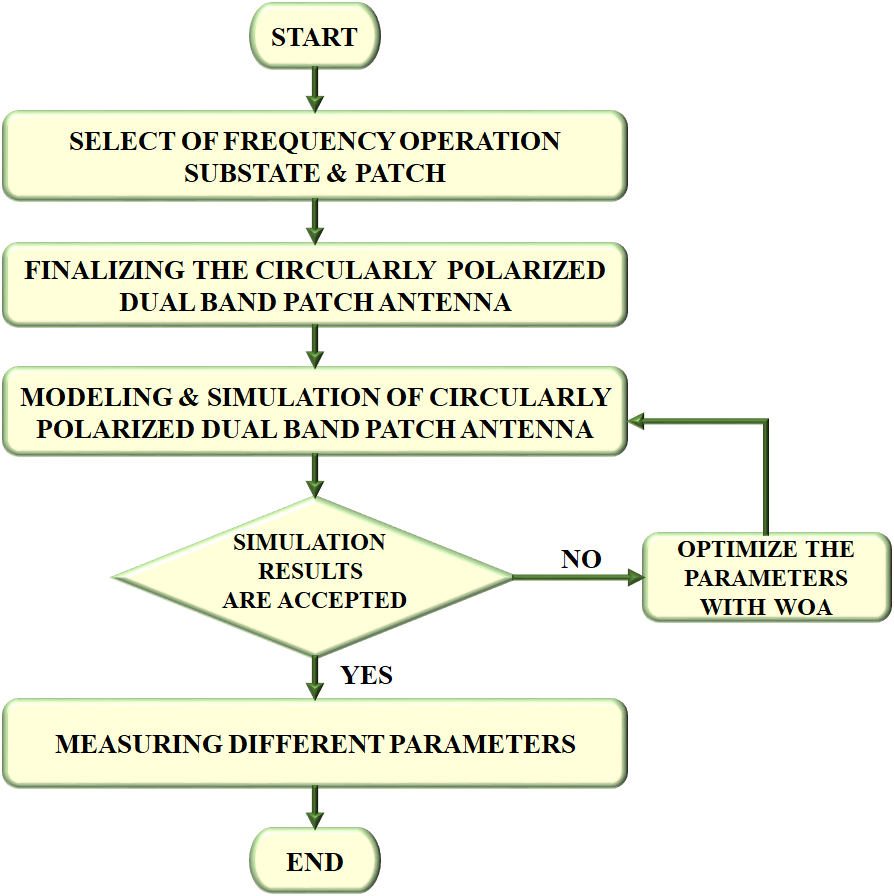
Figure 2. Flowchart of proposed antenna design
The summary of the pseudo-code will help you better understand about the functionality of WOA. The Whale optimisation method is used to distribute a collection of random responses to each population member while the initialization process. Then, for each iteration, the position and distance vectors regarding the target are generated in accordance with perhaps the best fitness values so far reached or a random search pattern. Phases of the process called exploitation and exploration are controlled by the parameter . Finally, the parameter b toggles between a spiral-tilted updating position mechanism and an encircling system with a shrinking radius. The population size is 30, total number of iterations are 50. The stopping criteria is met when maximum number of iterations are reached. Table 1 lists the ideal values of the structural factors that produce the best outcomes.
Pseudo-Code |
1. Initialization: the number of decision variables  is to be defined in the optimization problem is to be defined in the optimization problem 2. Determine the number of whales in the population  3. For each member of the population  , calculate the position vector , calculate the position vector 4. Determine the best position vector  in the population member. in the population member. 5. While  do do 6. for  do do 7. Compute  8  9.  10.  11. Calculate using equation (15) 12. Calculate  using equation (16) using equation (16) 13. else 14. Calculate  using (9) using (9) 15. Calculate using (10) 16. endif 17. else 18. Calculate using (13) 19. endif 20. end for 21. end for 22. Assign: G=G+1 23. end |
- RESULTS AND DISCUSSION
Figure 3 in this section depicts the view of a circular patch antenna. The improved results of antenna design have been simulated and presented. In this proposed system, simulation was carried out using ANSYS software HFSS for evaluating parameters like gain, return loss and efficiency. In accordance with a design framework, the proposed antenna is optimized using the WOA. The antenna's parameters are tuned to the required frequency band, which produces more favorable outcomes and high gain values.
Figure 4 depicts the return loss for 2.4GHZ and 5GHZ. Here, the return loss of -14.2 dB and -4.58 dB is attained by the 2.4GHZ and 5GHZ of proposed antenna, enhances the efficacy and signal quality. The VSWR of 2.4GHZ and 5GHZ is presented in Figure 5. The lowest VSWR of 1.478 dB and highest VSWR of 3.88 dB is attained by 2.4GHZ and 5GHZ, denoting the maximum power transfer. Figure 6 reveals the radiation efficiency for 2.4GHZ and 5GHZ bands. The radiation efficiency is 79.05 % at 2.4 GHZ and 74.83 % at 5 GHZ, indicates the antenna performance is improved.
The radiation pattern of E and H plane at 2.4GHZ is presented in Figure 7. The main lobe magnitude for these planes are 2.65 dB and 6.82 dB. Figure 8 displays the radiation pattern at 5 GHZ. The E plane and H plane has the main lobe magnitude of -8.88dB and -4.58 dB with distinct main lobe directions, thereby the better signal strength is offered. The gain plot for 2.4GHZ and 5GHZ bands is shown in Figure 9. Here, the maximum gain of 2.6353dB is attained by the 2.4GHZ than the lowest gain of 1.157dB, thereby compensate the path loss in the communication systems.
Figure 10 depicts the axial ratio plot for 2.4 and 5GHZ. The axial ratio for 2.4 and 5GHZ are 15.47dB and 2.49 dB, which is vital for measuring the purity of CP. With various algorithms, including ACO, CSA, PSO, and WOA, the convergence speed is compared. Figure 11 depicts it. It is evident from the Figure 11 that the WOA converge quickly than other methods. It can be seen from the above-mentioned graph that the WOA algorithm takes less time to execute than other algorithms like ACO and CSA, as seen in Figure 12. In terms of consumption time and convergence speed, the suggested optimizer performs better than the other methods.
In Table 2, the developed antenna is compared with other antenna design. The Table 2 clearly illustrates that the proposed work achieves superior performance. In contrast to existing circularly polarized antennas, our design features a lower profile. The developed antenna has the simple design with the better performance than other antennas. The gain of develop antennas is 2.6353dB, which is better than the gain of MIMO (2.6dB) [29] and 4 element MIMO (2.2 dB) [30] antennas, denotes the reliability of the antenna is enhanced, as seen in Figure 13.
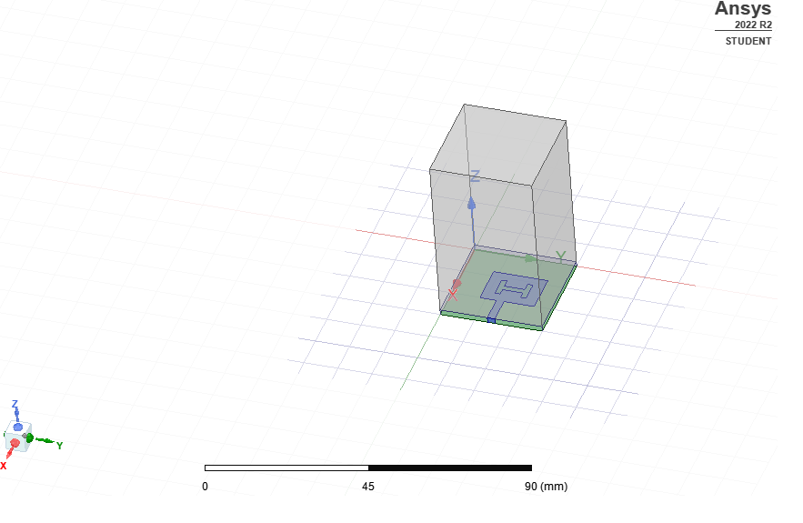
Figure 3. View of Circular patch antenna
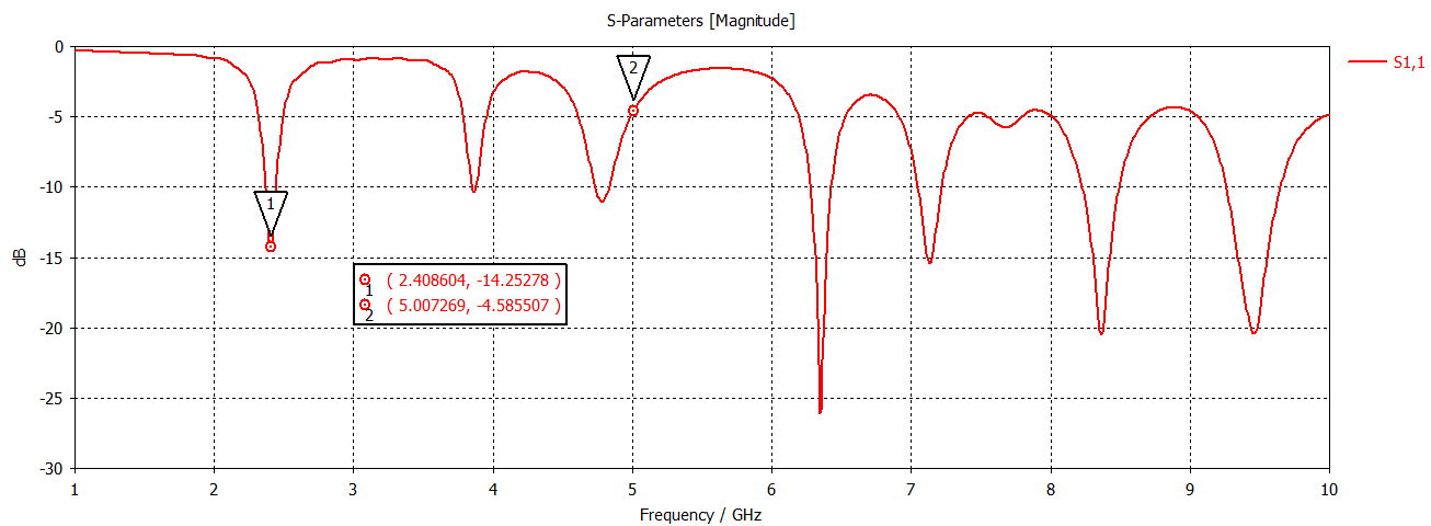
Figure 4. Return loss
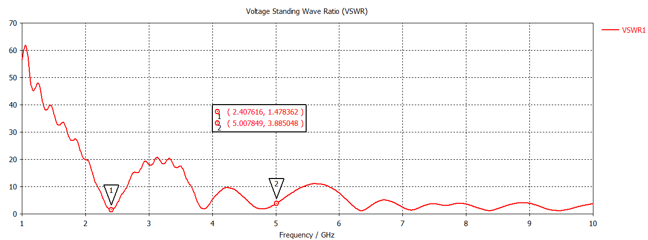
Figure 5. VSWR
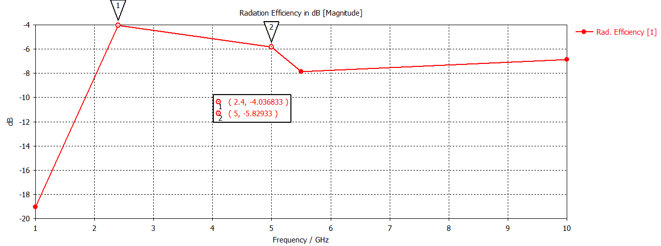
Figure 6. Radiation efficiency
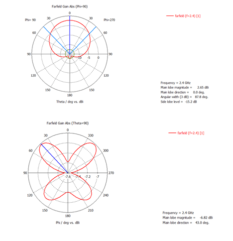
Figure 7. Radiation pattern at 2.4GHZ
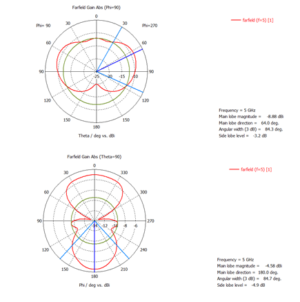
Figure 8. Radiation pattern at 5 GHZ
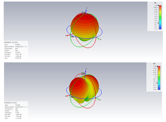
Figure 9. Gain
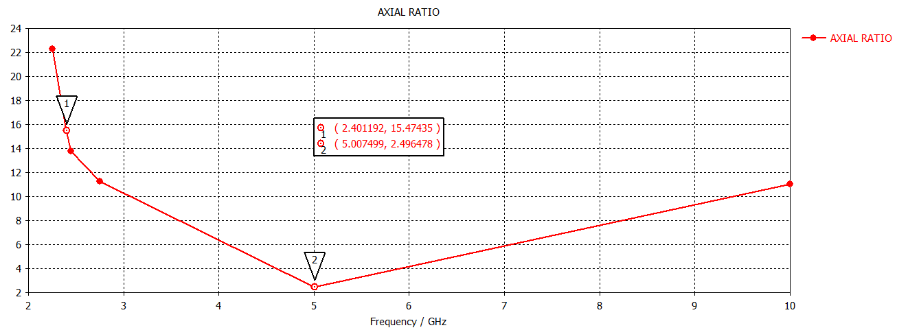
Figure 10. Axial ratio
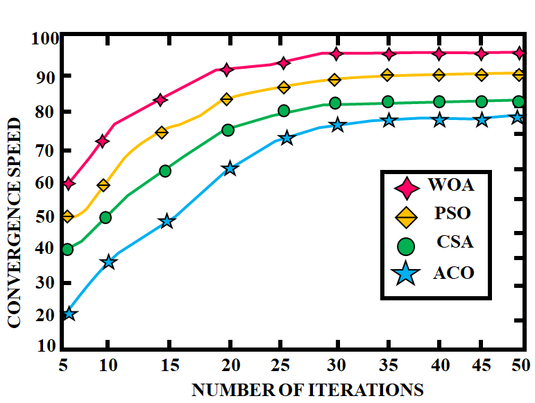
Figure 11. Comparison of Convergence speed
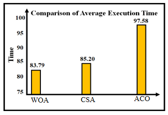
Figure 12. Analysis of average execution time
Table 2. Analysis of Antenna designs
Particulars | Ref [15] | Ref [16] | Proposed work |
Design | Complex | Simple | Simple |
Number of bands | single | Single | Dual |
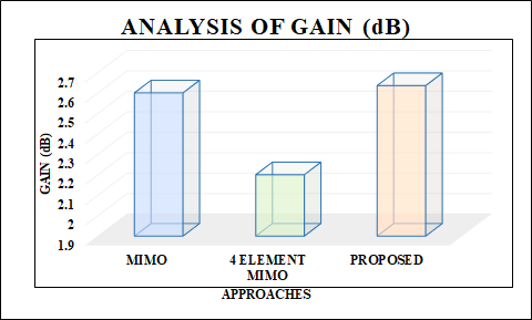
Figure 13. Analysis of gain
- CONCLUSION
This framework proposes a dual-band CP antenna with a circular patch and a ring slot as the upper and lower band radiator. By integrating each pair of notches on the two radiators, CP radiation gets generated. The suggested system was constructed, and the simulated values of various antenna parameters were explored. The antenna performs better in terms of gain, return loss, directivity, and efficiency in this setup. The circularly polarised patch antenna has 2.63 dB and 1.157 dB as gain and return loss accordingly, at 2.4 and 5 GHZ. Additionally, it reaps the advantages of having merely one layer, a simple structure, and minimal expenditure on manufacturing. Since the WOA effectively adjusted a number of the antenna's parameters to increase gain and bandwidth, it could also be used to improve other radio frequency components, such arrays or filters, where a number of interdependent factors need to be balanced. In addition to this, it achieves maximum total efficiency, and more consistent CP gain when compared to the state-of-the-art of several circular polarization antenna designs. It makes this architecture to be utilized in several applications, including RFID systems, GNSS receivers, and satellite communication. This research offers a beneficial approach since the Whale Algorithm's integration has the possible to increase system performance with efficiency of 79.05 %. Additionally, the optimized parameters are sensitive to fabrication error that shift resonant frequencies. Furthermore, the approach is need to be generalized to aid more than 2 bands allowing wider compatibility with next-generation wireless systems. Exploring the tunable or reconfigurable structure also improve its adaptability.
REFERENCE
- S. Liu, L. Yang, Q. Chen, and X. Wu, “A low‐profile broadband circularly polarized metasurface antenna aperture coupled by shorted annular‐ring slot,” International Journal of Antennas and Propagation, vol. 2022, no. 1, pp. 8517646, 2022, https://doi.org/10.1155/2022/8517646.
- G. Liu, X. Sun, X. Chen, D. Xiong, M. Li, and M.C. Tang, “A Broadband Low-Profile Dual-Linearly Polarized Dipole-Driven Metasurface Antenna,” IEEE Antennas and Wireless Propagation Letters, vol. 19, No. 8, pp. 1759-1763, 2020, https://doi.org/10.1109/LAWP.2020.3017173.
- D. Qin, B. Sun, and R. Zhang, “VHF/UHF Ultrawideband Slim Monopole Antenna with Parasitic Loadings,” IEEE Antennas and Wireless Propagation Letters, vol. 21, no. 10, pp. 2050-2054, 2022, https://doi.org/10.1109/LAWP.2022.3190015.
- C. E. Santosa, J. T. S. Sumantyo, S. Gao, and K. Ito, “Broadband circularly polarized microstrip array antenna with curved-truncation and circle-slotted parasitic,” IEEE Transactions on Antennas and Propagation, vol. 69, no. 9, pp. 5524-5533, 2021, https://doi.org/10.1109/TAP.2021.3060122.
- Z. Chen, X. Zheng, C. Song, J. Zhang, V. Volskiy, Y. Li, and G. A. E. Vandenbosch, “Enhancing circular polarization performance of low-profile patch antennas for wearables using characteristic mode analysis,” Sensors, vol. 23, no. 5, pp. 2474, 2023, https://doi.org/10.3390/s23052474.
- H. Liao, and A. Shamim, “A low-profile and high-aperture-efficiency hexagonal circularly polarized microstrip antenna array,” IEEE Antennas and Wireless Propagation Letters, vol. 21, no. 3, pp. 615-619, 2022, https://doi.org/10.1109/LAWP.2021.3139943.
- Y.H. Yang, B.H. Sun, and J.L. Guo, “A Single-Layer Wideband Circularly Polarized Antenna for Millimeter-Wave Applications,” IEEE Transactions on Antennas and Propagation, vol. 68, no. 6, pp. 4925-4929, 2020, https://doi.org/10.1109/TAP.2019.2951518.
- D. Fazal, and Q.U. Khan, “Dual-Band Dual-Polarized Patch Antenna Using Characteristic Mode Analysis,” IEEE Transactions on Antennas and Propagation, vol. 70, no.3, pp. 2271-2276, 2022, https://doi.org/10.1109/TAP.2021.3111341.
- Z. Li, Y. Zhu, H. Yang, G. Peng and X. Liu, "A Dual-Band Omnidirectional Circular Polarized Antenna Using Composite Right/Left-Handed Transmission Line With Rectangular Slits for Unmanned Aerial Vehicle Applications," in IEEE Access, vol. 8, pp. 100586-100595, 2020, https://doi.org/10.1109/ACCESS.2020.2999369.
- H. Zhai, K. Zhang, S. Yang, and D. Feng, “A Low-Profile Dual-Band Dual-Polarized Antenna with an AMC Surface for WLAN Applications,” IEEE Antennas and Wireless Propagation Letters, vol. 16, pp. 2692–2695, 2017, https://doi.org/10.1109/LAWP.2017.2741465.
- W. Wang, C. Chen, S. Wang, and W. Wu, “Switchable dual-band dual-sense circularly polarized patch antenna implemented by dual-band phase shifter of±90°,” IEEE Transactions on Antennas and Propagation, vol. 69, no. 10, pp. 6912-6917, 2021, https://doi.org/10.1109/TAP.2021.3070055.
- M. Mirmozafari, G. Zhang, S. Saeedi, and R.J. Doviak, “A Dual Linear Polarization Highly Isolated Crossed Dipole Antenna for MPAR Application,” IEEE Antennas and Wireless Propagation Letters, vol. 16, no. 3, pp. 1879-1882, 2017, https://doi.org/10.1109/LAWP.2017.2684538.
- F. Jia, S. Liao, and Q. Xue, “A Dual-Band Dual-Polarized Antenna Array Arrangement and Its Application for Base Station Antennas,” IEEE Antennas and Wireless Propagation Letters, vol. 19, no. 6, pp. 972-976, 2020, https://doi.org/10.1109/LAWP.2020.2985171.
- C. D. Bui, N. Nguyen-Trong, and T. K. Nguyen, “A planar dual-band and dual-sense circularly polarized microstrip patch leaky-wave antenna,” IEEE antennas and wireless propagation letters, vol. 19, no. 12, pp. 2162-2166, 2020, https://doi.org/10.1109/LAWP.2020.3026067.
- H. Yang, Y. Fan, and X. Liu, “A Compact Dual Band Stacked Patch Antenna with Dual Circular Polarizations for BeiDou Navigation Satellite Systems,” IEEE Antennas and Wireless Propagation Letters, vol.18, no. 7, pp. 1472-1476, 2019, https://doi.org/10.1109/LAWP.2019.2920265.
- Z. Zhao, F. Liu, J. Ren, Y. Liu, and Y. Yin, “Dual-sense circularly polarized antenna with a dual-coupled line,” IEEE Antennas and Wireless Propagation Letters, vol. 19, no. 8, pp. 1415-1419, 2020, https://doi.org/10.1109/LAWP.2020.3003943.
- L. Zhu, N. Alkhaldi, H.M. Kadry, S. Liao, and P.Y. Chen, “A Compact Hybrid-Fed Microstrip Antenna for Harmonics-Based Radar and Sensor Systems,” IEEE Antennas and Wireless Propagation Letters, vol. 17, no. 10, pp. 2444-2448, 2018, https://doi.org/10.1109/LAWP.2018.2877674.
- Z. Chen and H. Wong, “Liquid dielectric resonator antenna with circular polarization reconfigurability,” IEEE Transaction on Antennas and Propagation, vol. 66, no. 1, pp. 444–449, 2018, https://doi.org/10.1109/TAP.2017.2762005.
- U. Ullah, S. Koziel and I. B. Mabrouk, "A Simple-Topology Compact Broadband Circularly Polarized Antenna With Unidirectional Radiation Pattern," in IEEE Antennas and Wireless Propagation Letters, vol. 18, no. 12, pp. 2612-2616, 2019, https://doi.org/10.1109/LAWP.2019.2945543.
- J. Tang, G. Liu, and Q. Pan, “A Review on Representative Swarm Intelligence Algorithms for Solving Optimization Problems: Applications and Trends,” IEEE/CAA Journal of Automatica Sinica, Vol. 8, No. 10, pp. 1621-1641, 2021, https://doi.org/10.1109/JAS.2021.1004129.
- J. Gao, Y. Tian, and X. Chen, “Antenna Optimization Based on Co-Training Algorithm of Gaussian Process and Support Vector Machine,” IEEE Access, vol. 8, no. 12, pp. 211380-211390, 2020, https://doi.org/10.1109/ACCESS.2020.3039269.
- X. Wu, S. Zhang, W. Xiao and Y. Yin, "The Exploration/Exploitation Tradeoff in Whale Optimization Algorithm," in IEEE Access, vol. 7, pp. 125919-125928, 2019, https://doi.org/10.1109/ACCESS.2019.2938857.
- S. Stadler, and J. Igel, “Developing realistic FDTD GPR antenna surrogates by means of particle swarm optimization,” IEEE Transactions on Antennas and Propagation, vol. 70, no. 6, pp. 4259-4272, 2022, https://doi.org/10.1109/TAP.2022.3142335.
- R. H. Elabd, and A. J. Abdullah Al-Gburi, “Design and Optimization of a Circular Ring-Shaped UWB Fractal Antenna for Wireless Multi-Band Applications Using Particle Swarm Optimization,” Progress In Electromagnetics Research B, vol. 106, pp. 101-112, 2024, https://doi.org/10.2528/PIERB24033002.
- H. A. Malhat, A. S. Zainud-Deen, M. Rihan, and M. M. Badway, “Elements failure detection and radiation pattern correction for time-modulated linear antenna arrays using particle swarm optimization,” Wireless Personal Communications, vol. 125, no. 3, pp. 2055-2073, 2022, https://doi.org/10.1007/s11277-022-09645-7.
- J. Li, P. Xue, and W. Wang, “Pilot contamination suppression method for massive MIMO system based on ant colony optimization,” Wireless Networks, vol. 28, no. 5, pp. 1879-1888, 2022, https://doi.org/10.1007/s11276-022-02942-w.
- D. Fazal, and Q. U. Khan, “Dual-band dual-polarized patch antenna using characteristic mode analysis,” IEEE Transactions on Antennas and Propagation, vol. 70, no. 3, pp. 2271-2276, 2021, https://doi.org/10.1109/TAP.2021.3111341.
- C. Zhang, X. Fu, L.P. Ligthart, S. Peng, and M. Xie, “Synthesis of Broadside Linear Aperiodic Arrays With Sidelobe Suppression and Null Steering Using Whale Optimization Algorithm,” IEEE Antennas and Wireless Propagation Letters, vol. 17, no. 1, pp. 347-350, 2018, https://doi.org/10.1109/LAWP.2018.2789919.
- C. Essid, C. Abdelhamid, F. A. Almalki, O. Ali, and H. Sakli, “New MIMO Antenna with Filtration for the Future Multiuser Systems in Satellite Communications,” Wirel. Commun. Mob. Comput., vol. 2022, no. 1, pp. 1040333, 2022, https://doi.org/10.1155/2022/1040333.
- G. Singh, S. Kumar, B. K. Kanaujia, and V. K. Pandey, “Design and performance analysis of a frequency reconfigurable four-element multiple-input-multiple-output antenna,” AEU Int. J. Electron. Commun. vol. 146, pp. 154118, 2022, https://doi.org/10.1016/j.aeue.2022.154118.
N. Nirmal Singh (Design and Optimization of Circularly Polarized Dual Band Patch Antenna Using Whale Optimization Algorithm for Wireless Communications)