ISSN: 2685-9572 Buletin Ilmiah Sarjana Teknik Elektro
Vol. 7, No. 4, December 2025, pp. 807-822
Improving Performance and Safety in Mechanical Ventilation: A Robust Control Approach for Airway Pressure and Patient Flow
Nooralhuda Salman, Saleem K. Kadhim
Department of Control and System Engineering, University of Technology-Iraq, Baghdad 10066, Iraq
ARTICLE INFORMATION |
| ABSTRACT |
Article History: Received 16 July 2025 Revised 23 October 2025 Accepted 14 November 2025 |
| 
The mechanical ventilation system demand precise and highly responsive control for airway pressure (Paw) and the patient flow (Qpat) as system nonlinearities and time varying disturbances for example the changes in lung mechanics or patient effort it compromise patient safety and treatment efficacy. This study addresses to critical challenge of the robust regulation by comparing two advanced nonlinear control strategies which ar: the Nonlinear PID (NPID) controller and the Active Disturbance Rejection Control with Nonlinear PD structure (ADRC-NPD) controller. The research utilizes a state space model of the respiratory system that developed and simulated in the MATLAB/Simulink for rigorously test controller performance under abrupt changes in the desired pressure setpoint (Pset). The model incorporate clinically relevant lung mechanics that including fixed values for the airway resistance (Rl) and lung compliance (Cl) to represent specific patient scenario. Performance is assessed using key metrics are rise time, overshoot/undershoot, settling time and tracking error. The ADRC-NPD controller consistently demonstrated superior performance that attributed to it Extended State Observer (ESO) for real time estimation and compensation of total system disturbances. Specifically the ADRC-NPD achieved a significantly faster rise time reach to (0.174s vs. 0.38s) and minimal undershoot (-0.3025% vs. -16.573%) compared to the NPID controller that indicating exceptional tracking fidelity and stability crucial for patient well being. The findings strongly that suggest that the ADRC-NPD provides a more robust and clinically viable control solution. Future work will focus on the real-time clinical simulation and hardware in the-loop implementation to validate these results under dynamic and patient specific conditions. |
Keywords: Mechanical Ventilation; Active Disturbance Rejection Control (ADRC); Airway Pressure Control; Patient Flow Regulation; Respiratory System Dynamics |
Corresponding Author: Nooralhuda Salman, Department of Control and System Engineering, University of Technology-Iraq, Baghdad 10066, Iraq. Email: cse.23.12@grad.uotechnology.edu.iq |
This work is open access under a Creative Commons Attribution-Share Alike 4.0 
|
Document Citation: N. Salman and S. K. Kadhim, “Improving Performance and Safety in Mechanical Ventilation: A Robust Control Approach for Airway Pressure and Patient Flow,” Buletin Ilmiah Sarjana Teknik Elektro, vol. 7, no. 4, pp. 807-822, 2025, DOI: 10.12928/biste.v7i4.14283. |
INTRODUCTION
The human respiratory system is a complex network responsible for gas exchange, delivering oxygen, and removing carbon dioxide. It consists of conducting airways (nose, trachea, bronchi) that transport air and respiratory zones (alveoli) where gas exchange occurs. Proper function depends on lung compliance, airway resistance, neurological control, and chemical feedback (O₂, CO₂, pH). Diseases like asthma, COPD and ARDS can disrupt these mechanisms it often necessitating medical intervention [1]-[8]. When natural breathing fails the mechanical ventilation becomes critical that providing life support through volume controlled or pressure controlled methods. However due to the respiratory system dynamic and nonlinear nature advanced ventilation strategies are increasingly used to enhance precision and adaptability in critical care [9]-[11].
The research delves explicitly into advanced control strategies for the respiratory system which is comparing the performance of the Nonlinear Proportional-Integral-Derivative (NPID) controller and the Active Disturbance Rejection Control-Nonlinear PD (ADRC-NPD) controller [12]-[17]. The NPID is controller extends the capabilities of a classical PID controller by introducing nonlinear functions in its proportional, integral or derivative terms that allowing for more adaptive and robust performance in systems with inherent nonlinearities such like the varying resistance and compliance of the lungs [19]-[24].
The challenge in controlling the mechanical ventilation systems from a systems perspective lies in the inherent limitations of conventional PID and many classical robust control strategies when faced with the highly nonlinear and dynamically uncertain characteristics of the respiratory system. Specifically the system exhibit time varying parameters (changes in lung compliance and resistance), patient-specific variability and unmodeled dynamics (like breathing effort and leaks) that act as significant that rapidly changing total disturbances. Current control methods often rely on linear approximations or require extensive scenario-specific tuning that resulting in performance trade-offs either slow response times and significant overshoot/undershoot which can lead to the delayed patient synchronization and inefficient gas exchange or an aggressive response that risks ventilator that induced lung injury (VILI). The necessitates a control paradigm that can effectively and continuously decouple the system known dynamics from its unknown disturbances. While nonlinear PID (NPID) offers improvement over linear control, it still struggles with robustly handling these varying, external disturbances. Therefore, a critical research gap exists in utilizing and validating advanced control structures, such as the ADRC-NPD configuration, whose core innovation—the Extended State Observer (ESO) explicitly estimates and compensates for the lumped total disturbance that offering a unique capability to achieve superior tracking, faster settling times and guaranteed stability in the complex, disturbance-prone respiratory environment, a performance level not convincingly demonstrated by existing adaptive or other robust frameworks in this critical application [25]-[27].
However significant unmodeled dynamics and external disturbances can still challenge its effectiveness. The ADRC-NPD controller is incorporates the principle of active disturbance rejection [28]. To estimate the total disturbance which can be includes both external disturbances influencing the respiratory system and internal unmodeled dynamics ADRC uses an Extended State Observer (ESO) [29]-[34]. That been estimated disturbance is then actively compensated for allowing the embedded Nonlinear PD controller to act on a more predictable, linearized system. It is proactive disturbance compensation is hypothesized to provide superior control performance, leading to better regulation of airway pressure, improved patient flow characteristics, and minimized tracking errors, even in the face of complex and often unpredictable respiratory system dynamics [35]-[37].
Regarding NPID controllers research has shown their utility in overcoming some limitations of conventional linear PID controllers in systems with variable dynamics, which is highly relevant to mechanical ventilation. For instance, a study by [38] this research strived to identify the optimal control strategy that can assure maximal patient safety and efficient ventilator operation. it compared three control strategies: the conventional Proportional-Integral-Derivative (PID) control, the Nonlinear PID control, and the sliding mode control (SMC) equipped with signum function triggers.
For Active Disturbance Rejection Control (ADRC), including ADRC-NPD, its application in various complex systems, and by extension, its potential for respiratory systems, stems from its robust anti-disturbance capabilities and reduced reliance on precise models. While specific studies directly named "ADRC-NPD for respiratory system" might be emerging, the principles of ADRC have been explored for systems with similar characteristics. For instance, research on pneumatic actuators [39] and permanent magnet synchronous motors [40], which also deal with inherent nonlinearities and external disturbances, has demonstrated the effectiveness of ADRC in reducing oscillations and improving control accuracy through its Extended State Observer (ESO) that estimates and compensates for total disturbances. The core concept of ADRC, where disturbances and uncertainties are lumped together and actively rejected, makes it a highly suitable candidate for respiratory control where factors like patient effort, airway secretions, and changes in lung mechanics act as significant disturbances [41]-[43]. The integration of an ESO allows for real-time estimation of these unmeasured disturbances, enabling the controller to maintain performance even when the precise model of the patient's respiratory system is unknown or changing. The application of ADRC principles, combined with a Nonlinear PD structure, offers a promising approach to achieve robust and precise control of respiratory variables like airway pressure and patient flow, providing superior performance compared to traditional or basic nonlinear PID methods by proactively countering adverse effects. The rest of the paper is organized as follows: Section 2 details the methodology and mathematical models, including the dynamics and control of the respiratory system, nonlinear PID, and ADRC-NPD Section 3 presents the numerical results and analysis for each simulation scenario. Finally, Section 4 provides the conclusions and outlines potential future work.
METHODOLOGY
Dynamics and Control of the Respiratory System
Figure 1 presents a simplified schematic of a mechanical ventilation system that serving as the foundation for developing a mathematical model of the respiratory system and its state-space representation [44]-[48]. In this diagram the blower simulates the ventilator generating airflow ( ) at pressure (
 ) which is delivered through a hose modeled with resistance (
 ). The sensor tube measures the airway pressure (
 ) while a leak path characterized by resistance (
 ) the accounts for potential air losses (
 ). Air continues into the test lung which mimics human lung behavior using a resistive element (Rₗ) representing airway resistance and a compliance element (
 ) representing lung elasticity. The pressure and flow within the lung are denoted by
  and
and  respectively. The structured layout with clearly defined resistive and capacitive components that enables the derivation of dynamic equations needed for a state-space model which is crucial for analyzing system behavior and designing effective control strategies in the mechanical ventilation applications [49]-[55].
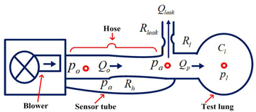
Figure 1. A Mechanical Ventilation Unit is Schematic [56]
By examining the connections between the system fluxes and the pressures a dynamical model can be constructed to capture its essential dynamics. From Figure 1 the lungs draw in air at an airflow rate of () and concurrently release a flow rate of () through a leaky hose that leaving ( ) as the remaining exhaled airflow [57].
| 
| (1) |
An electric circuit is a similar concept for the respiratory system. where resistances represent obstacles to airflow, pressures correspond to voltage and the airflow resembles electric current. Using Ohm law [58] the patient airflow can be mathematically represented with a pressure sensor measuring airway pressure ( ).
).
The control system primary goal is to ensure that the measured pressure accurately tracks the intended set point ( ), leading to the formulation of an error equation to achieve precise pressure regulation [59]:
| 
| (2) |
The conventional resistances connected to the hose can be used to indicate the blower (), patient (), and leak () flow rates, leak channel, and the patient lungs as shown below [58]-[59]:
| 
| (3) |
The blower output pressure is denoted by , the airway pressure by , the hose resistance by , the resilience of the leak by , and the lung resistance by  . Lung dynamics and lung pressure
  satisfy the following differential equation.
| 
| (4) |
where lung compliance (elastance) is denoted by  . Equation (3) is equal to current and is equal to voltage. The following expression can be obtained by substituting equation (3) into equation (4):
| 
| (5) |
The airway pressure (in Pascals) can be obtained rewrite the airway pressure equation by substituting equations (3) into equation (1). This will yield equation (6).
| 
| (6) |
The following updated equation is obtained by substituting the airway pressure expression from equation (6) into the lung dynamics equation in equation (5):
| 
| (7) |
Equation ((3), equation (6), and equation (7)) can be used to model the patient and hose system as a linear state-space system with . serving as both the input and the output.  , and Plung is the state.
| 
| (8) |
| 
| (9) |
where:
| 
| (10) |
Alternatively, it can be represented in transfer function notation as follows:
| 
| (11) |
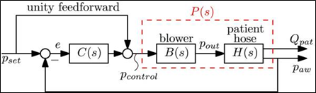
Figure 2. System of closed-loop control using a linear controller C(s) [60]
The module's output pressure, or  , is precisely controlled by the blower mechanism. As shown in Figure 2, a direct relationship between the intended pressure (
 ) and the actual output pressure () results in a perfect match (a ratio of 1). At higher frequencies, the blower's inherent inertia causes dynamic behavior that impairs performance. A second-order low-pass filter is a decent way to emulate it.
| 
| (12) |
With damping ratio  and
and  , this corresponds to a real experimental blower. Equation (12) can be expressed using state space format as
| 
| (13) |
With state  , output , and control input , and system matrices
| 
| (14) |
The general state space form of the plant  can be described as follows by combining the blower dynamics (Equation (6)) and the patient hose system dynamics (to be controlled by the feedback controller as seen in the Figure 2) [16]–[18].
The transfers function is being computed from the state-space representation, where S is the Laplace variable, and I represent the Identity matrix (with dimensions matching  (. Table 1 provides essential information about the characteristics of the simulated ventilator system. The numerical values and units of the parameters offer insights into the system behavior that including its resistance to airflow, lung compliance, leakages and dynamic response. The information is crucial for understanding the system performance and the designing effective control strategies.
Table 1. Ventilator system's parameters [61]
Name | value | Parameter |
| 0.005  | Lung resistance |
|  
| Lung’s compliance (capacitance) |
| 0.06 | Leak resistance |
| 
| Hose resistance |

| 376.8 rad/s | Natural frequency |
| 1 | damping ratio |
Nonlinear PID
The NPID utilizes a nonlinear function typically a saturation or  function on the error term to provide a small gain for small errors (avoiding oscillation) and large gain for large errors (ensuring fast response). The inherent design choice aims to balance speed and stability which is essential in a life-support system [62]. Its nonlinearity allows it to adapt to the complex and the time-varying characteristics of the respiratory mechanics [63]. A simplified mathematical representation of the respiratory system model can be given by a second-order differential equation, reflecting the compliance and resistance of the respiratory system:
| 
| (18) |
where  is the airway pressure,
  is the lung volume, C is the respiratory system compliance,
  is the respiratory system resistance,
  represents the elastic recoil pressure of the lungs (which can be the nonlinear with volume),
  is the pressure generated by the respiratory muscles, and
  is the pressure supplied by the ventilator [64]-[66].
The NPID controller aims to manipulate the ventilator pressure to achieve the desired airway pressure which is the  . The control action
  generated by a basic form of the NPID controller can be expressed as [67]-[68]:
| 
| (19) |
where  is the tracking error,
  ,
,  , and
, and  are the proportional, integral, and derivative gain parameters, respectively The key aspect of a nonlinear PID controller lies in the functions
  and
and  , which introduce nonlinearity based on the tracking error. These functions can take various forms such as saturation functions, power functions or piecewise linear functions that allowing the controller gains to effectively change depending on the magnitude or sign of the error.
The three controller parameters (, , ) were initially tuned using the Ziegler-Nichols method on the linearized plant model and that resulting values were then subjected to iterative fine tuning within the MATLAB/Simulink environment to optimize for the minimal Integral Absolute Error (IAE) and reduced the overshoot under the step response test. The final selected gain values represent the best trade off found for speed and stability can be seen in Figure 3 [69].
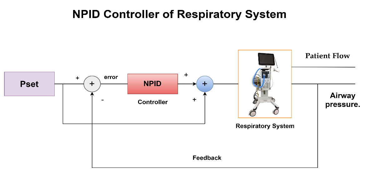
Figure 3. Control System Block Diagram With NPID Controller For Respiratory System
ADRC-NPD
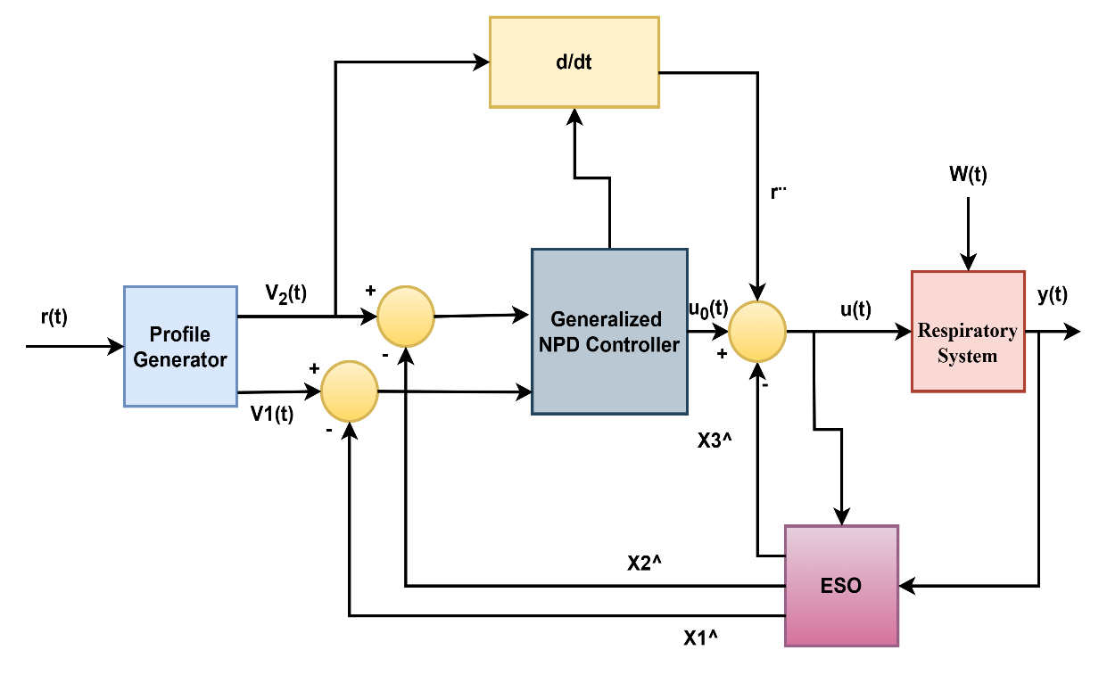
The ADRC control paradigm fundamentally differs from traditional PID-type controllers by actively estimating and compensating for unknown disturbances and internal dynamics, often called "total disturbance." Unlike a conventional Nonlinear PD (NPD) controller, which primarily reacts to the error between the setpoint and the measured output, the ADRC-NPD combines the robust disturbance rejection capabilities of ADRC with the structure of a nonlinear proportional-derivative controller. The ESO is the core component. It is a full-order observer designed to simultaneously estimate the system state (e.g., ) and the lumped total disturbance (f). The total disturbance encapsulates the internal nonlinearities, unmodeled dynamics and external variations. Integrating the ESO into the loop redefines the control problem from handling an uncertain plant to controlling a known disturbance-free linear integrator dramatically improving robustness. Figure 4 shows the structure of ADRC-NPD [70].
Figure 4. ADRC-NPD Controller Block Diagram
In an ADRC-NPD configuration, the ESO provides a real-time estimate of the total disturbance, which is fed back into the control loop. The NPD part of the controller, having this disturbance information, can then focus on achieving good tracking performance for the nominal system. The proactive disturbance rejection allows the ADRC-NPD to maintain robust performance despite significant model uncertainties, parameter variations and the external disturbances common in complex systems like the respiratory system. The "nonlinear" aspect of the PD is component might involve using nonlinear gains or functions of the error to improve transient response or handle specific operating regimes more effectively than a linear PD controller. The combination leverages the strengths of both approaches the adaptability and robustness of ADRC to handle the unknown and the fast response and simplicity of a well tuned NPD to track desired trajectories. That makes ADRC-NPD particularly well suited for systems where precise control is needed despite unpredictable changes and inherent nonlinearities.The general mathematical derivation of ADRC-NPD is provided by [71].
The provided set of equation (20) and equation (21) from source describes a tracking differentiator, a common component in ADRC used to generate smooth derivatives of a reference signal while also filtering noise. Equation (20) defines  as the derivative of
  . In the context of a tracking differentiator, if is tracking a signal, then would be its estimated first derivative.
| 
| (20) |
That is a nonlinear dynamics equation for the second state . Here, r represents the reference signal that is trying to track. The term  introduces an intense, discontinuous control action based on the sign of the error between and the reference
  . The term
  provides damping proportional to the square of , helping to smooth the derivative estimation and prevent chattering.
The parameters  are suitable design specifications, where
  , and
, and  .
.
In this research, equation (21) can be modified by making some an assumption as:
| 
| (24) |
| 
| (25) |
It enhances trajectory tracking performance and is better than the conventional nonlinear tracking differentiator equation (21). For (ADRC-NPD), equation (3) and equation (10) can be written after adding nonlinear function as:
| 
| (26) |
Where  is defines the primary tracking error
  as the difference between the reference signal r and the estimated state
  .
.  is defined as a second error
  as the difference between the derivative of the reference signal
  (likely from the tracking differentiator) and the estimated derivative of the state
  .
.  is the core nonlinear PD control law. It uses nonlinear functions (given by Eq. (27)) for errors and . and are the proportional and derivative gains.
  is the final control output
  . Here,
  ˙ represents the estimate of the ESO's total disturbance, subtracted from the nominal control action
  .
.  is an estimated control gain. This subtraction is the essence of active disturbance rejection. The NPD state error feedback law (using a nonlinear function ) processes the error between the TD output and the ESO's state estimates. The gains (,) were selected based on the desired control bandwidth (
 ) to ensure the closed-loop system dynamics meet the desired transient performance specifications (rise time, settling time).
| 
| (27) |
RESULTS
The results will focus on the comparison between ADRC-NPD and previous studies [38] that depend on the NPID controller. The current study (ADRC-NPD) will be in a blue line, and the previous study will be in a red line. Figure 5 illustrates the first scenario's airway pressure ( ) response, comparing the ADRC-NPD and NPID controllers. The graph shows the desired setpoint () in yellow, the NPID controller's response in red, and the ADRC-NPD controller's response in blue. Initially, both controllers start at zero mbar. At approximately 3 seconds, the setpoint abruptly changes to 20 mbar. The ADRC-NPD controller quickly rises reach to 19.6849 mbar at 3.174 seconds and it reaches 19.9395 mbar at 3.36 seconds that closely tracking the 20 mbar references. In contrast the NPID controller reacts slower that reaching 16.6854 mbar at 3.194 seconds and 186459 mbar at 338 seconds that showing a significant undershoot and sluggish response. Physically the suggests the ADRC-NPD controller active disturbance rejection capability allows it to handle the sudden change in the desired pressure more effectively. The ADRC estimates and compensates for system uncertainties and disturbances that leading to a faster and more accurate response. The NPID controller lacking the disturbance rejection, struggles to adapt rapidly that resulting in the observed delay and undershoot.
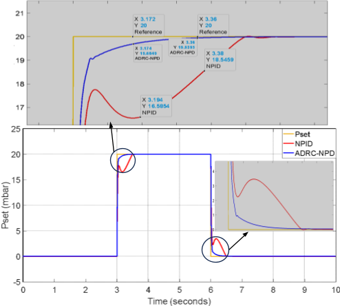
Figure 5. Response of Airway Pressure () in the Initial Situation
Table 2 shown the comparison of the ADRC-NPD and NPID controller Performance in Paw. The ADRC-NPD controller outperforms the NPID controller in the all three metrics. In terms of rise time the ADRC-NPD is much more quicker. The ADRC-NPD also demonstrates minimal overshoot while the NPID has a significant undershoot and a sluggish approach to the setpoint. The settling time is significantly shorter for the ADRC-NPD controller that indicating a faster and more stable response. The active disturbance rejection capabilities of the ADRC-NPD which allow it to react swiftly and precisely to variations in the desired pressure are responsible for its exceptional performance.
Table 2. Comparison of ADRC-NPD and NPID Controller Performance (Paw - First Scenario).
Parameter | ADRC-NPD | NPID |
Rise Time (s) | 0.174 | 0.38 |
Overshoot (%) | -0.3025 | -16.573 |
Settling Time (s) | 3.36 | 3.38 |
The patient flow () response in the first scenario is shown in the Figure 6 which is compares the NPID and ADRC-NPD controllers. Figure 6 shows the flow rate over time in the milliliters per a minute. Initially both controllers maintain a flow rate of approximately zero. At around 3 seconds there a significant change in the flow corresponding to the change in setpoint observed in Figure 6. The NPID controller exhibits a sharp spike that reaching nearly  mL/min followed by a rapid decrease and then a sustained flow around
  mL/min for a period before dropping again close to
  around 6 seconds. The ADRC-NPD controller shows a much more controlled response with a smaller peak around
  mL/min and a quicker settling back to near zero flow for both after the initial change and the change back to zero.
Physically the significant spike and prolonged deviation in the NPID controller response indicate a less stable and less efficient management of the flow dynamics. The NPID controller overreact to the pressure change and that causing a surge in flow and a slower return to the baseline. The ADRC-NPD controller is smoother response suggests better control over the airflow such likely due to its ability to the compensate for the system dynamic changes and disturbances also it providing a more stable and physiologically reasonable flow pattern. The ADRC-NPD controller manages the patient flow more effectively than the NPID controller that minimizing drastic fluctuations and ensuring a more stable response to the changes in desired airway pressure.
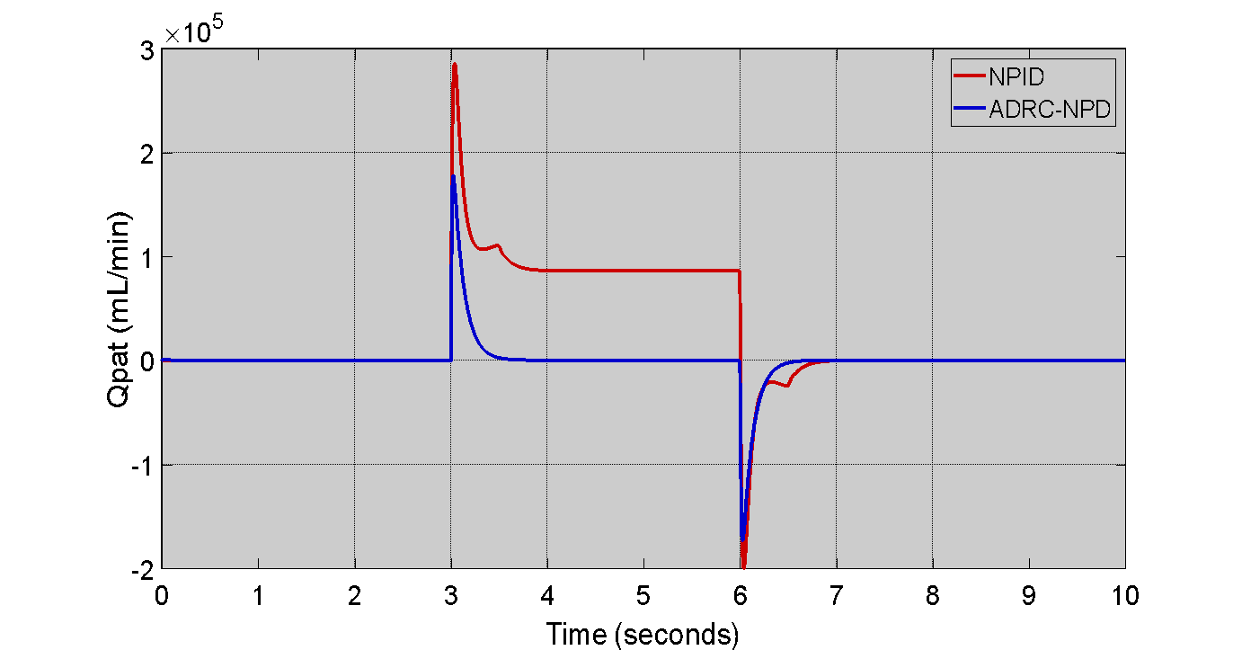
Figure 6. Patient Flow () Response in the First Scenario
Comparing the NPID and ADRC-NPD controllers. Figure 7 shows the airway pressure () tracking error for the first scenario. Initially, both controllers exhibit minimal error close to zero. Up to around 3 seconds the error remains to negligible. At the approximately reach to 3 seconds when the setpoint changes a significant error develops for the NPID controller. The NPID error is plunges to nearly to -0.8 which indicating a substantial deviation from the desired pressure and it remains at the level for a considerable period. The ADRC-NPD controller also shows a dip in error but it is much smaller only around -0.2, and quickly recovers to near zero. Physically the demonstrates the superior tracking capability of the ADRC-NPD controller. The NPID controller inability to precisely follow the intended pressure changes is indicated by the large mistake in its response that reflecting its sluggishness and undershooting as seen in Figure 7. The ADRC-NPD controller with its active disturbance rejection maintains a much smaller tracking error that indicating that it can more precisely control the airway pressure and adhere to the setpoint changes. The highlights the ADRC-NPD effectiveness in the minimizing deviations from the intended pressure profile. The accuracy of the ADRC-NPD controller in regulating the airway pressure is demonstrated by its noticeably superior tracking performance and reduced tracking mistakes as compared to the NPID controller.
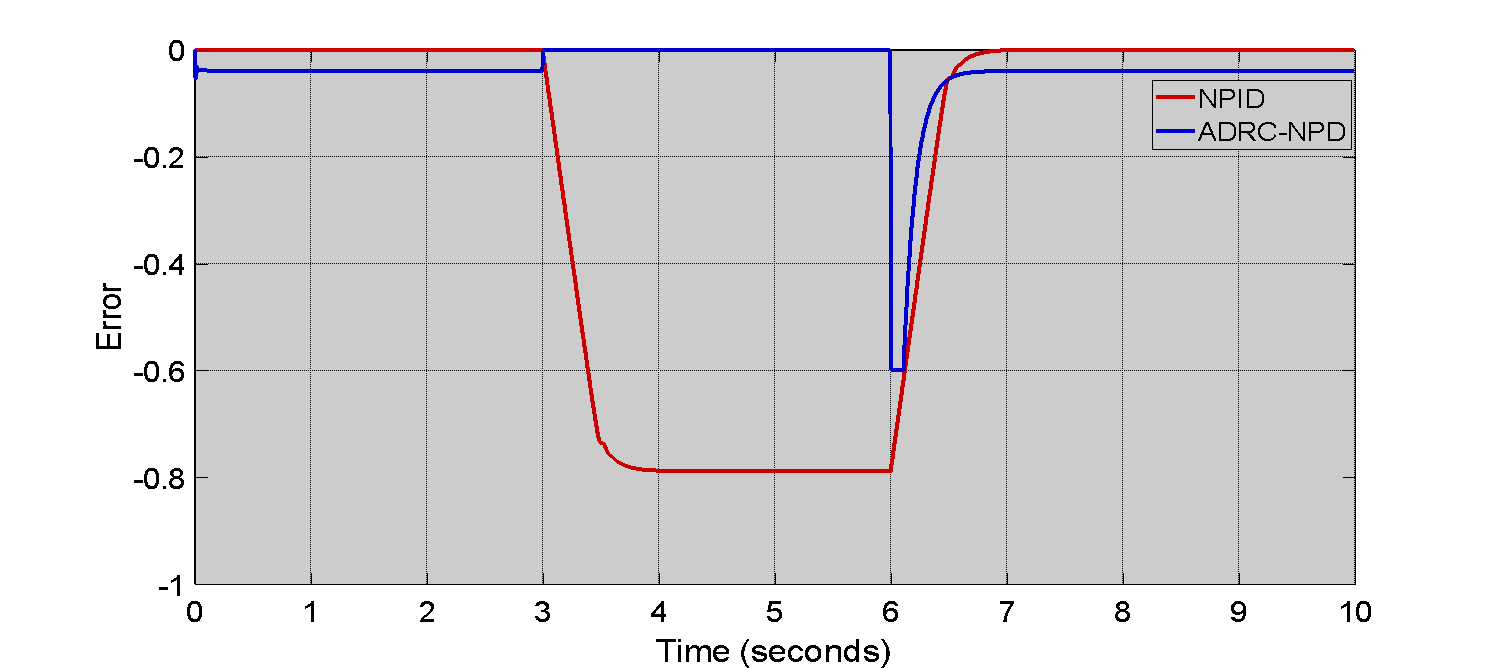
Figure 7. Tracking Error of Airway Pressure () in First Scenario
Figure 8 illustrates the second scenario airway pressure () response that focusing solely on the ADRC-NPD controller. Figure 8 shows the desired setpoint () in red and the actual airway pressure response of the ADRC-NPD controller in blue color. Initially both the setpoint and the controller response start at zero mbar and increase linearly reach to 20 mbar over the first 2 seconds. The ADRC-NPD controller tracks the setpoint which very closely during this ramp up phase. At approximately reach to 12 seconds, the setpoint abruptly drops back down to 0 mbar. The ADRC-NPD controller follows this drop though the a slight delay and a small deviation before it settles back to 0 mbar as highlighted in the inset zoom view. The inset shows that at 12.588 seconds the ADRC-NPD response is 11.088 mbar while at 12.876 seconds the response is 85.0757 mbar. Physically the close tracking during the ramp up indicates the ADRC-NPD controller ability to accurately follow gradual changes in the desired pressure. The slight delay and deviation observed during the abrupt drop suggest that even with its disturbance rejection capabilities the a brief period where the controller adjusts to the sudden change in dynamics. However the controller quickly recovers and stabilizes that demonstrating its effectiveness in managing airway pressure.
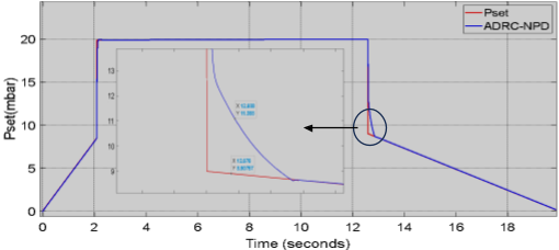
Figure 8. Airway Pressure () Response in Second Scenario
Table 3 clearly illustrates the superior performance of the ADRC-NPD controller in terms of tracking error in the first scenario, as depicted in Figure 8. The most significant difference is in the peak negative error are: the ADRC-NPD controller shows a peak negative error of approximately to -0.2 which is substantially smaller than the NPID controller peak negative error of approximately to -0.8. That indicates that the ADRC-NPD controller maintains the airway pressure much closer to the desired setpoint even during transient changes.
Table 3. Comparison of ADRC-NPD and NPID Controllers - Tracking Error
Parameter | ADRC-NPD | NPID |
Peak Negative Error | -0.2 | -0.8 |
Settling Time (s) | 3.2 | 6.0 |
Figure 9 shows the patient flow () response for the second scenario specifically in the ADRC-NPD controller. Initially the flow rate is close to the zero. Around 2 seconds ther a positive spike in flow that reaching approximately to  mL/min. The spike corresponds to the initial ramp up of the airway pressure observed in Figure 9. After the spike the flow settles back to near zero. The flow remains close to the zero until around 12 seconds. The negative spike it dropping to approximately to
  mL/min. The negative spike aligns with the abrupt drop in airway pressure seen in Figure 9. Following this spike the flow returns to near zero again. The initial positive flow spike physically represents the air delivered to the patient lungs as the pressure increases. The subsequent settling to near zero indicates that the flow stabilizes once the desired pressure reached and maintained. The negative flow spike at 12 seconds signifie the exhalation or air flow out of the lungs as the pressure decreases. The ADRC-NPD controller modulate the airflow to achieve the desired pressure changes.
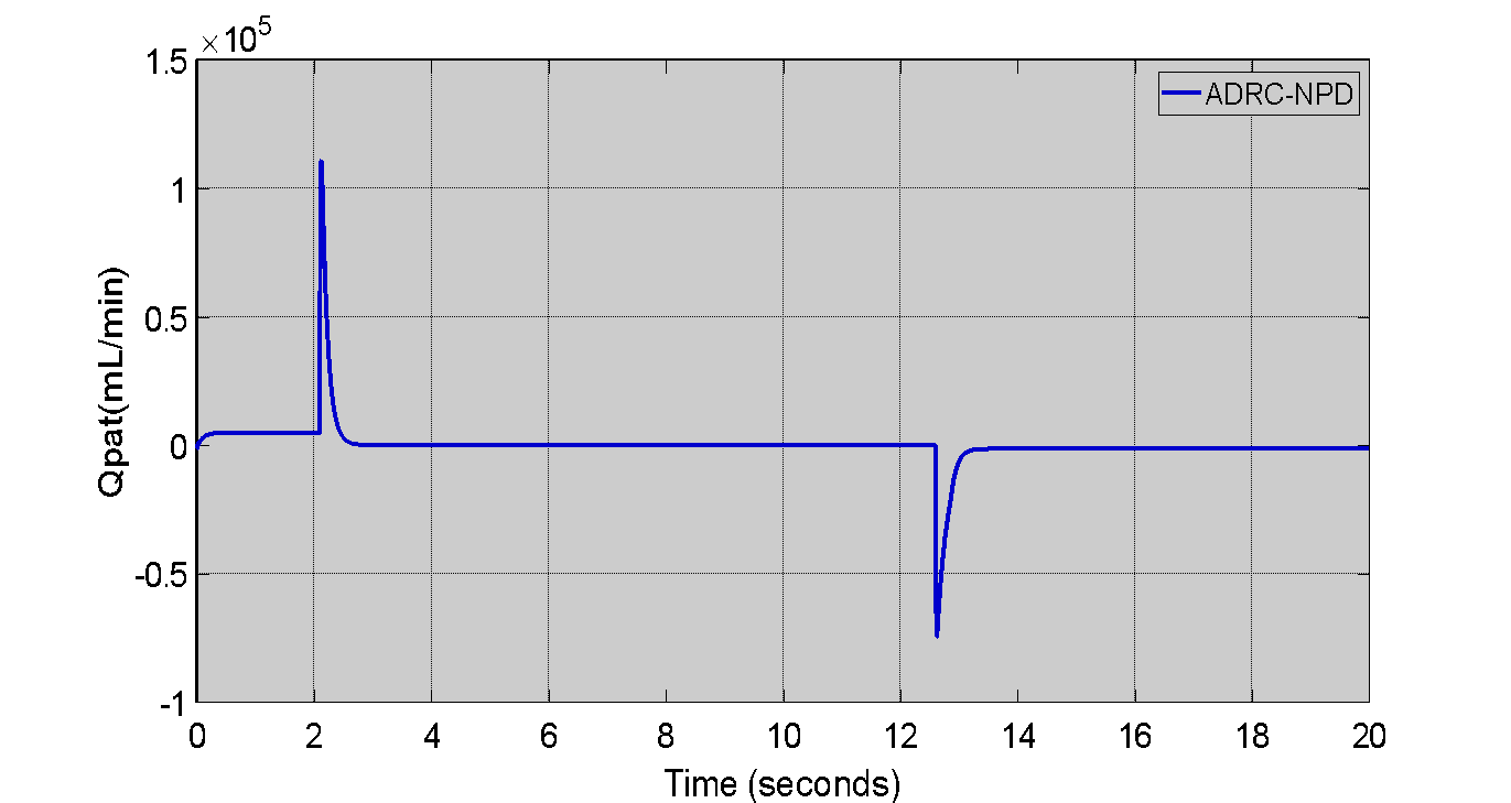
Figure 9. Patient Flow () Response in Second Scenario
The airway pressure () tracking error for the ADRC-NPD controller in the second case as shown in Figure 10. Initially the tracking error is close to zero that indicating that the ADRC-NPD controller accurately follows the desired pressure. As observed in Figure 10 a minor negative error spike around 2 seconds that dropping to approximately to -0.05. The corresponds to the initial ramp-up of pressure. That is another larger negative error spike at around 12 seconds that reaching approximately to -0.6. The larger spike aligns with the abrupt drop in desired pressure in Figure 10. After each spike the error quickly returns to near zero. Physically the small error during the ramp up and the larger error during the abrupt drop reflects the controller adjustment to changing in the pressure demands. Even though the ADRC-NPD controller minimizes error the transient spikes indicate that instantaneous perfect tracking is challenging especially during sudden changes. The rapid return to near zero error demonstrates the controller ability to correct deviations and maintain accurate pressure control quickly.
While the ADRC-NPD controller demonstrates superior performance in the simulated respiratory system its advanced structure introduces specific practical challenges. The primary drawback is increased computational complexity. Unlike the three-term NPID controller the ADRC-NPD requires the simultaneous operation of the Tracking Differentiator (TD) and the (ESO) which adds several integration and state estimation calculations to every control cycle. That increased computational load demands faster processing capabilities which can be a significant constraint for low cost or embedded systems typically used in portable or bedside ventilators potentially leading to real-time implementation challenges and higher hardware costs. A second major drawback is its higher sensitivity to the parameter tuning. The performance of the ADRC-NPD is critically dependent on the tuning of the ESO bandwidth ( ) and the control law bandwidth (
 ). A poorly tuned that can lead to an inaccurate or slow disturbance estimate negating the benefit of the ADRC and causing performance degradation or conversely an overly high can amplify measurement noise. Achieving the necessary separation principle (where is much faster than
  ) requires meticulous and specialized tuning procedures that are more complex and less intuitive than the iterative tuning applied to traditional PID or NPID controllers that presenting a steeper learning curve for practical application engineers.
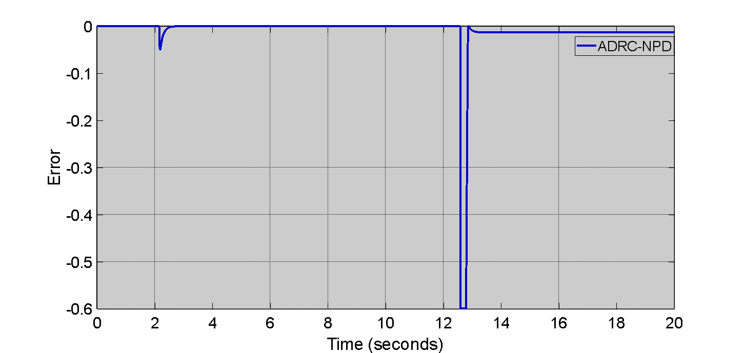
Figure 10. Tracking Error Of Airway Pressure () In Second Scenario
CONCLUSION
The study successfully demonstrated the superior performance of the (ADRC-NPD) controller compared to the NPID controller for regulating and in the MATLAB/Simulink simulation of the respiratory system. The results are unequivocally show that the ADRC-NPD achieves a significantly faster more precise tracking response characterized by a superior rise time and minimal undershoot. That robust performance is directly attributable to the ESO which effectively estimates and cancels the total lumped disturbance that including system nonlinearities which leading to high stability even during abrupt setpoint changes. However the current findings are based solely on a simplified state-space model and cannot be directly extrapolated to the clinical outcomes. The claims regarding enhanced of patient safety, synchronization and reduced risk of respiratory trauma remain speculative as the simulation does not incorporate critical physiological factors such as spontaneous patient breathing effort, variable lung mechanics or the intricate biological mechanisms of the ventilator-induced lung injury (VILI).
The implementation of the ADRC-NPD introduces notable the limitations that must be addressed before clinical viability can be established. The control structure entails increased computational complexity compared to NPI posing challenges for real-time deployment on cost-sensitive, embedded ventilator hardware. The performance is also highly sensitive to the specialized tuning of the ESO bandwidth (). The critical dependence means that factors inherent to real-world deployment such as sensor noise, actuator constraints and sampling delays that could significantly degrade the accuracy of the disturbance estimation and undermine the theoretical benefits. The ADRC-NPD controller presents theoretically compelling and numerically superior robust control solution for mechanical ventilation. Future work is essential to bridge the gap between simulation and the clinical reality. The must involve hardware in the loop implementation to validate computational feasibility and testing against complex the dynamic physiological models that incorporate patient variability that providing the necessary evidence to support its claims as a next generation solution for safer and more effective critical care.
Future work will focus on three critical areas. First we plan to enhance the system model by incorporating time varying lung mechanics (compliance and resistance) spontaneous patient breathing efforts (muscle pressure) and clinically relevant disturbances such as leakage effects and measurement noise. That will be achieved by moving to a higher-order multi-compartment physiological model to test the ADRC-NPD robustness under dynamic patient-specific uncertainty. Second we will undertake a comprehensive real-time validation study via hardware in the loop (HIL) simulation. That involves deploying the ADRC-NPD algorithm onto an embedded control platform (a high-speed microcontroller or Field Programmable Gate Array) and connecting it to a physical or high fidelity pneumatic lung simulator. The step is crucial for assessing computational latency that tuning sensitivity to hardware constraints and stability under non-ideal, asynchronous sampling conditions. Third the research will expand its scope to include multivariable control objectives specifically focusing on the simultaneous regulation of pressure and volume or flow and the design of an AdaptiveADRC variant. The adaptive approach would allow the controller critical gains particularly the ESO bandwidth to be automatically adjusted based on estimated patient parameters thereby simplifying the initial tuning process and ensuring robust performance across diverse clinical scenarios without manual recalibration.
REFERENCES
- A. K. Abbas and S. K. Kadhim, “Eliminating Chattering in Prosthetic Fingers Using Classic Synergetic Control,” Journal Européen des Systèmes Automatisés, vol. 58, no. 1, 2025, https://doi.org/10.18280/jesa.580109.
- D. S. Shanan and S. K. Kadhim, “Comparative Analysis of Airflow Regulation in Ventilator Systems Using Various Control Strategies,” Journal Europeen des Systemes Automatises, vol. 56, no. 5, pp. 811–821, 2023, https://doi.org/10.18280/jesa.560512.
- D. Sheltag and S. K. Kadhim, “Enhancing Artificial Ventilator Systems: A Comparative Analysis of Traditional and Nonlinear PID Controllers,” Mathematical Modelling of Engineering Problems, vol. 11, no. 3, pp. 599–610, 2024, https://doi.org/10.18280/mmep.110303.
- A. El-Hadj, M. Kezrane, H. Ahmad, H. Ameur, S. Z. B. Abd Rahim, A. Younsi,and H. Abu-Zinadah, “Design and simulation of mechanical ventilator,” Chaos Solitons Fractals, vol. 150, p. 111169, 2021, https://doi.org/10.1016/j.chaos.2021.111169.
- M. Pavone, E. Verrillo, A. Onofri, S. Caggiano, and R. Cutrera, “Ventilators and Ventilatory Modalities,” Front Pediatr, vol. 8, 2020, https://doi.org/10.3389/fped.2020.00500.
- M. E. A. Abdelrahim, H. Saeed, H. S. Harb, and Y. M. Madney, “Types of Mechanical Ventilation,” in Essentials of Aerosol Therapy in Critically ill Patients, pp. 27–43, 2021, https://doi.org/10.1007/978-3-030-85026-5_2.
- C. R. Rackley, “Monitoring During Mechanical Ventilation,” Respir Care, vol. 65, no. 6, pp. 832–846, 2020, https://doi.org/10.4187/respcare.07812.
- J. M. Walter, T. C. Corbridge, and B. D. Singer, “Invasive Mechanical Ventilation,” South Med J, vol. 111, no. 12, pp. 746–753, 2018, https://doi.org/10.14423/SMJ.0000000000000905.
- A. S. Tran, H. Q. Thinh Ngo, V. K. Dong, and A. H. Vo, “Design, Control, Modeling, and Simulation of Mechanical Ventilator for Respiratory Support,” Math Probl Eng, vol. 2021, pp. 1–15, 2021, https://doi.org/10.1155/2021/2499804.
- D. Chiumello, M. Gotti, M. Guanziroli, P. Formenti, M. Umbrello, I. Pasticci, , and M.Busana, “Bedside calculation of mechanical power during volume- and pressure-controlled mechanical ventilation,” Crit Care, vol. 24, no. 1, p. 417, 2020, https://doi.org/10.1186/s13054-020-03116-w.
- D. Chiumello et al., “Bedside calculation of mechanical power during volume- and pressure-controlled mechanical ventilation,” Crit Care, vol. 24, no. 1, p. 417, 2020, https://doi.org/10.1186/s13054-020-03116-w.
- I. A. Saidin, M. N. Maslan, L. Abdullah, F. Yakub, and A. N. Chairat, “Performance Analysis of Conditional Integrator in NPID Controller as Cutting Force Compensator for Machine Tools Application,” In Symposium on Intelligent Manufacturing and Mechatronics, pp. 79-85, 2021, https://doi.org/10.1007/978-981-16-8954-3_8.
- X. Ming, H. Zhang, H. Hu, T. Wang, and S. Ren, “Gas Proportional Mixing Module Based on Parallel Active Disturbance Rejection Control for Mechanical Ventilation,” in 2024 8th International Conference on Automation, Control and Robots (ICACR), pp. 108–112, 2024, https://doi.org/10.1109/ICACR62205.2024.11053716.
- J. Arcos-Legarda and A. Tovar, “Mechatronic Design and Active Disturbance Rejection Control of a Bag Valve-Based Mechanical Ventilator,” J Med Device, vol. 15, no. 3, 2021, https://doi.org/10.1115/1.4051064.
- D. I. R. Almeida et al., “Modeling and control of an invasive mechanical ventilation system using the active disturbances rejection control structure,” ISA Trans, vol. 129, pp. 345–354, 2022, https://doi.org/10.1016/j.isatra.2021.12.021.
- J. Arcos-Legarda and A. Tovar, “Mechatronic Design and Active Disturbance Rejection Control of a Bag Valve-Based Mechanical Ventilator,” J Med Device, vol. 15, no. 3, 2021, https://doi.org/10.1115/1.4051064.
- C. R. Rackley, “Monitoring During Mechanical Ventilation,” Respir Care, vol. 65, no. 6, pp. 832–846, 2020, https://doi.org/10.4187/respcare.07812.
- A. Abdurrakhman, T. Soehartanto, H. S. Hadi, M. B. Toriki, B. L. Widjiantoro, and B. Sampurno, “Design of Output Power Control System Based on Mass Flow Rate Comparison of Air-Fuel Ratio (AFR) on Dual Fuel Generator Set by Using PID Control Method,” International Journal of Technology, vol. 11, no. 3, p. 574, 2020, https://doi.org/10.14716/ijtech.v11i3.2710.
- S. Zelenika et al., “Energy Harvesting Technologies for Structural Health Monitoring of Airplane Components—A Review,” Sensors, vol. 20, no. 22, p. 6685, 2020, https://doi.org/10.3390/s20226685.
- A. Abdurrakhman, T. Soehartanto, H. S. Hadi, M. B. Toriki, B. L. Widjiantoro, and B. Sampurno, “Design of Output Power Control System Based on Mass Flow Rate Comparison of Air-Fuel Ratio (AFR) on Dual Fuel Generator Set by Using PID Control Method,” International Journal of Technology, vol. 11, no. 3, p. 574, 2020, https://doi.org/10.14716/ijtech.v11i3.2710.
- G. Rausa, M. Calabrese, R. Velazquez, C. Del-Valle-Soto, R. De Fazio, and P. Visconti, “Mechanical, Thermal, and Environmental Energy Harvesting Solutions in Fully Electric and Hybrid Vehicles: Innovative Approaches and Commercial Systems,” Energies (Basel), vol. 18, no. 8, p. 1970, 2025, https://doi.org/10.3390/en18081970.
- D. S. Shanan and S. K. Kadhim, “Comparative Analysis of Airflow Regulation in Ventilator Systems Using Various Control Strategies,” Journal Européen des Systèmes Automatisés, vol. 56, no. 5, pp. 811–821, 2023, https://doi.org/10.18280/jesa.560512.
- G. Li, H. Sun, Y. Ye, L. Chen, W. Zhang, S. Yu, and L. Fan, “Clinical utility of nanopore-targeted sequencing for diagnosing and treating pulmonary infectious diseases from bronchoalveolar lavage fluid,” Front Cell Infect Microbiol, vol. 15, 2025, https://doi.org/10.3389/fcimb.2025.1469440.
- H. Jin, J. Song, W. Lan, and Z. Gao, “On the characteristics of ADRC: a PID interpretation,” Science China. Information Sciences, vol. 63, no. 10, p. 209201, 2020, https://doi.org/10.1007/s11432-018-9647-6.
- P. Chen and Y. Luo, “A Two-Degree-of-Freedom Controller Design Satisfying Separation Principle with Fractional-Order PD and Generalized ESO,” IEEE/ASME Transactions on Mechatronics, vol. 27, no. 1, pp. 137–148, 2022, https://doi.org/10.1109/TMECH.2021.3059160.
- J. Michalski, M. Mrotek, D. Pazderski, P. Kozierski, and M. Retinger, “Improving Performance of ADRC Control Systems Affected by Measurement Noise Using Kalman Filter-Tuned Extended State Observer,” Electronics (Basel), vol. 13, no. 24, p. 4916, 2024, https://doi.org/10.3390/electronics13244916.
- X. Hua, D. Huang, and S. Guo, “Extended State Observer Based on ADRC of Linear System with Incipient Fault,” Int J Control Autom Syst, vol. 18, no. 6, pp. 1425–1434, 2020, https://doi.org/10.1007/s12555-019-0052-2.
- G. Tang, W. Xue, H. Peng, Z. Yang, and Y. Zhao, “Parallel Multiple Extended State Observers Based ADRC With Application to High-Speed Precision Motion Stage,” IEEE Transactions on Industrial Electronics, vol. 71, no. 8, pp. 9639–9648, 2024, https://doi.org/10.1109/TIE.2023.3323744.
- W. Liu and G. Wu, “Automatic clutch control using ADRC with continuous adaptive extended state observer,” International Journal of Robust and Nonlinear Control, vol. 35, no. 1, pp. 82–101, 2025, https://doi.org/10.1002/rnc.7641.
- Z. Zhang, J. Cheng, and Y. Guo, “PD-Based Optimal ADRC with Improved Linear Extended State Observer,” Entropy, vol. 23, no. 7, p. 888, 2021, https://doi.org/10.3390/e23070888.
- D. S. Shanan and S. K. Kadhim, “Comparative Analysis of Airflow Regulation in Ventilator Systems Using Various Control Strategies,” Journal Europeen des Systemes Automatises, vol. 56, no. 5, pp. 811–821, 2023, https://doi.org/10.18280/jesa.560512.
- Q. Wei, Z. Wu, Y. Zhou, D. Ke, and D. Zhang, “Active Disturbance-Rejection Controller (ADRC)-Based Torque Control for a Pneumatic Rotary Actuator with Positional Interference,” Actuators, vol. 13, no. 2, p. 66, 2024, https://doi.org/10.3390/act13020066.
- P. Gao, X. Su, Z. Pan, M. Xiao, W. Zhang, and R. Liu, “Active Disturbance Rejection Control for Speed Control of PMSM Based on Auxiliary Model and Supervisory RBF,” Applied Sciences, vol. 12, no. 21, p. 10880, 2022, https://doi.org/10.3390/app122110880.
- M. A. N. Abed, D. S. Shanan, and Z. H. H. Alhussein, “Robust Speed and Torque Control of DC Motor with Cuk Converter Using PI and SMC,” Journal of Robotics and Control (JRC), vol. 6, no. 3, pp. 1216–1226, 2025, https://doi.org/10.18196/jrc.v6i3.25756.
- M. A. Najm Abed, A. Abdul Razzaq Altahir, A. O. Hanfesh, and A. A. Ahmed, “Performance Evaluation of PMSM and BLDC Motors in Different Operating Scenarios Based Slide Mode Control,” in 2024 4th International Conference on Electrical Machines and Drives, ICEMD 2024, pp. 1-7, 2024, https://doi.org/10.1109/ICEMD64575.2024.10963593.
- M. Albaker Najm Abed, A. Abdul Razzaq Altahir, and A. Ahmed Abdulhadi Ahmed, “A Review of Hybrid Electric Vehicle Configurations: Advances and Challenges,” vol. 04, no. 03, 2024, https://doi.org/10.63463/kjes1155.
- T. R. Frieden and C. T. Lee, “Identifying and Interrupting Superspreading Events—Implications for Control of Severe Acute Respiratory Syndrome Coronavirus 2,” Emerg Infect Dis, vol. 26, no. 6, pp. 1059–1066, 2020, https://doi.org/10.3201/eid2606.200495.
- S. Sanche, Y. T. Lin, C. Xu, E. Romero-Severson, N. Hengartner, and R. Ke, “High Contagiousness and Rapid Spread of Severe Acute Respiratory Syndrome Coronavirus 2,” Emerg Infect Dis, vol. 26, no. 7, pp. 1470–1477, 2020, https://doi.org/10.3201/eid2607.200282.
- Y. Zhang et al., “New understanding of the damage of SARS-CoV-2 infection outside the respiratory system,” Biomedicine & Pharmacotherapy, vol. 127, p. 110195, 2020, https://doi.org/10.1016/j.biopha.2020.110195.
- O. S. Omelchenko et al., “Preparation of athletes in cyclic sports taking into account the functional state of the external respiratory system and cardiovascular system,” Pedagogy of Physical Culture and Sports, vol. 24, no. 2, pp. 93–99, 2020, https://doi.org/10.15561/26649837.2020.0207.
- C. F. Bennett, P. Latorre-Muro, and P. Puigserver, “Mechanisms of mitochondrial respiratory adaptation,” Nat Rev Mol Cell Biol, vol. 23, no. 12, pp. 817–835, 2022, https://doi.org/10.1038/s41580-022-00506-6.
- M. E. Sadiq, A. J. Humaidi, S. K. Kadhim, A. Al Mhdawi, A. Alkhayyat, and I. K. Ibraheem, “Optimal Sliding Mode Control of Single Arm PAM-Actuated Manipulator,” in 2021 IEEE 11th International Conference on System Engineering and Technology (ICSET), pp. 84–89, 2021, https://doi.org/10.1109/ICSET53708.2021.9612539.
- A. S. Ahmed and S. K. Kadhim, “Non-Leaner Control on the Pneumatic Artificial Muscles: A Comparative Study Between Adaptive Backstepping and Conventional Backstepping Algorithms,” Mathematical Modelling of Engineering Problems, vol. 10, no. 2, pp. 653–662, 2023, https://doi.org/10.18280/mmep.100236.
- A. El-Hadj et al., “Design and simulation of mechanical ventilators,” Chaos Solitons Fractals, vol. 150, p. 111169, 2021, https://doi.org/10.1016/j.chaos.2021.111169.
- M. Jaber, L. Hamawy, M. Hajj-Hassan, M. A. Ali, and A. Kassem, “MATLAB/Simulink Mathematical Model for Lung and Ventilator,” in 2020 32nd International Conference on Microelectronics (ICM), pp. 1–5, 2020, https://doi.org/10.1109/ICM50269.2020.9331820.
- A. S. Tran, H. Q. Thinh Ngo, V. K. Dong, and A. H. Vo, “Design, Control, Modeling, and Simulation of Mechanical Ventilator for Respiratory Support,” Math Probl Eng, vol. 2021, pp. 1–15, 2021, https://doi.org/10.1155/2021/2499804.
- P. Tamburrano, F. Sciatti, E. Distaso, L. Di Lorenzo, and R. Amirante, “Validation of a Simulink Model for Simulating the Two Typical Controlled Ventilation Modes of Intensive Care Units Mechanical Ventilators,” Applied Sciences, vol. 12, no. 4, p. 2057, 2022, https://doi.org/10.3390/app12042057.
- J. Giri, N. Kshirsagar, and A. Wanjari, “Design and simulation of AI-based low-cost mechanical ventilator: An approach,” Mater Today Proc, vol. 47, pp. 5886–5891, 2021, https://doi.org/10.1016/j.matpr.2021.04.369.
- D. Sheltag and S. K. Kadhim, “Enhancing Artificial Ventilator Systems: A Comparative Analysis of Traditional and Nonlinear PID Controllers,” Mathematical Modelling of Engineering Problems, vol. 11, no. 3, pp. 599–610, 2024, https://doi.org/10.18280/mmep.110303.
- I. M. Mehedi, H. S. M. Shah, U. M. Al-Saggaf, R. Mansouri, and M. Bettayeb, “Fuzzy PID Control for Respiratory Systems,” J Healthc Eng, vol. 2021, 2021, https://doi.org/10.1155/2021/7118711.
- M. Borrello, "Modeling and control of systems for critical care ventilation," Proceedings of the 2005, American Control Conference, 2005., pp. 2166-2180 vol. 3, 2005, https://doi.org/10.1109/ACC.2005.1470291.
- D. P. Redmond, K. T. Kim, S. E. Morton, S. L. Howe, Y. S. Chiew, and J. G. Chase, “A Variable Resistance Respiratory Mechanics Model,” in IFAC-PapersOnLine, pp. 6660–6665, 2017, https://doi.org/10.1016/j.ifacol.2017.08.1533.
- I. M. Mehedi, H. S. M. Shah, U. M. Al-Saggaf, R. Mansouri, and M. Bettayeb, “Fuzzy PID Control for Respiratory Systems,” J Healthc Eng, vol. 2021, pp. 1–6, Jun. 2021, https://doi.org/10.1155/2021/7118711.
- M. A. N. Abed, Z. S. Al Hakeem, M. S. Yasir, and A. O. Hanfesh, “Boosting Energy for Building-Integrated Photovoltaic Cells using Novel Boost Converter with Voltage Multiplier Cell and ANN-MPPT”, J Robot Control (JRC), vol. 6, no. 5, pp. 2212–2227, 2025, https://doi.org/10.18196/jrc.v6i5.26854.
- N. Ullah and A. S. Mohammad, “Cascaded robust control of mechanical ventilator using fractional order sliding mode control,” Mathematical Biosciences and Engineering, vol. 19, no. 2, pp. 1332–1354, 2022, https://doi.org/10.3934/mbe.2022061.
- B. Hunnekens, S. Kamps, and N. Van De Wouw, “Variable-Gain Control for Respiratory Systems,” IEEE Transactions on Control Systems Technology, vol. 28, no. 1, pp. 163–171, 2020, https://doi.org/10.1109/TCST.2018.2871002.
- D. Sheltag and S. K. Kadhim, “Enhancing Artificial Ventilator Systems: A Comparative Analysis of Traditional and Nonlinear PID Controllers,” Mathematical Modelling of Engineering Problems, vol. 11, no. 3, pp. 599–610, 2024, https://doi.org/10.18280/mmep.110303.
- I. M. Mehedi, H. S. M. Shah, U. M. Al-Saggaf, R. Mansouri, and M. Bettayeb, “Fuzzy PID Control for Respiratory Systems,” J Healthc Eng, vol. 2021, pp. 1–6, 2021, https://doi.org/10.1155/2021/7118711.
- N. Ullah and A. Mohammad, “Cascaded robust control of mechanical ventilator using fractional order sliding mode control,” Mathematical Biosciences and Engineering, vol. 19, no. 2, pp. 1332–1354, 2021, https://doi.org/10.3934/mbe.2022061.
- L. T. Rasheed, N. Q. Yousif, and S. Al-Wais, “Performance of the Optimal Nonlinear PID Controller for Position Control of Antenna Azimuth Position System,” Mathematical Modelling of Engineering Problems, vol. 10, no. 1, pp. 366–375, 2023, https://doi.org/10.18280/MMEP.100143.
- A. A. Najm and I. K. Ibraheem, “Nonlinear PID controller design for a 6-DOF UAV quadrotor system,” Engineering Science and Technology, an International Journal, vol. 22, no. 4, pp. 1087–1097, 2019, https://doi.org/10.1016/j.jestch.2019.02.005.
- B. Hunnekens, S. Kamps, and N. Van De Wouw, “Variable-Gain Control for Respiratory Systems,” IEEE Transactions on Control Systems Technology, vol. 28, no. 1, pp. 163–171, 2020, https://doi.org/10.1109/TCST.2018.2871002.
- N. A. Alawad; A. J. Humaidi; A. S. Alaraji, “Sliding mode-based active disturbance rejection control of assistive exoskeleton device for rehabilitation of disabled lower limbs,” Anais da Academia Brasileira de Ciências, vol. 95, no. 2, p. e20220680, 2023, https://doi.org/10.1590/0001-3765202320220680.
- H. Sun and D. Jiang, “Vibration suppression of magnetic bearing system based on active disturbance rejection control with generalized integrator extend state observer,” in 2020 IEEE 1st China International Youth Conference on Electrical Engineering, CIYCEE 2020, pp. 1-2, 2020. https://doi.org/10.1109/CIYCEE49808.2020.9332769.
Nooralhuda Salman (Improving Performance and Safety in Mechanical Ventilation: A Robust Control Approach for Airway Pressure and Patient Flow)