ISSN: 2685-9572 Buletin Ilmiah Sarjana Teknik Elektro
Vol. 8, No. 1, February 2026, pp. 51-63
Implementation of an Automatic Controlled Power Factor Correction System Utilizing Low-Cost Modules
Anees Abu Sneineh 1, Wael A. Salah 1, Alfian Ma'arif 2
1 Department of Electrical Engineering, College of Engineering and Technology, Palestine Technical University - Kadoorie, P.O.Box: 7, Yafa Street, Tulkarm, Palestine
2 Electrical Engineering Department, Industrial Technology Faculty, Universitas Ahmad Dahlan, Yogyakarta, Indonesia
ARTICLE INFORMATION |
| ABSTRACT |
Article History: Received 08 July 2025 Revised 29 December 2025 Accepted 10 January 2026 |
| 
This paper presents the design and implementation of a PIC microcontroller-based power factor correction system using a stepped capacitor bank and low-cost analog measurement modules. The proposed design aimed to address the low power factor issue caused by inductive loads that intern increases the current, losses, and apparent power demand. The developed PIC-based controller integrated analog conditioning circuits for voltage, current, and phase-angle measurement. The proposed system acquires analog signals from a voltage transformer, a current transformer–op-amp module, and an AD8302-based phase detector, computes real, reactive, and apparent power in real time, and automatically connects or disconnects capacitor-bank steps to maintain the power factor within a predefined band (0.92–0.98). Experimental results on a 4 kW inductive load array indicated that the measurement error of the analog voltage module was approximately 1.32%, while the analog current module exhibited an error of around 3.02% in comparison to digital measuring instruments. Additionally, there was an improvement in the power factor from 0.865 to 0.935, with by a reduction in load current of approximately 7% and a decrease in load reactive power of about 35%. The proposed design confirms satisfactory operation for automatic capacitor-bank control in power factor correction applications. |
Keywords: Power Factor Correction; PIC Microcontroller; Capacitor Bank; Signal Conditioning; Automatic Control; Analog Module |
Corresponding Author: Wael A. Salah, Department of Electrical Engineering, College of Engineering and Technology, Palestine Technical University - Kadoorie, P.O.Box: 7, Yafa Street, Tulkarm, Palestine. Email: wael.salah@ptuk.edu.ps |
This work is open access under a Creative Commons Attribution-Share Alike 4.0 
|
Document Citation: A. A. Sneineh, W. A. Salah, and A. Ma'arif, “Implementation of an Automatic Controlled Power Factor Correction System Utilizing Low-Cost Modules,” Buletin Ilmiah Sarjana Teknik Elektro, vol. 8, no. 1, pp. 51-63, 2026, DOI: 10.12928/biste.v8i1.14215. |
- INTRODUCTION
With today's increasing demand for electrical power, it has become imperative that electrical power systems provide as much apparent power as possible to supply all loads connected to the electrical grid with minimal losses and without the need for additional new generators. Adding new generators requires increasing the capacity of transmission and distribution networks in order to accommodate the increased current in the grid. There is a growing trend towards highly efficient and high-quality energy systems, especially when using multiple energy sources, both conventional and renewable, in response to the steady increase in energy demand. The increasing trend towards hybrid energy systems is also aimed at addressing energy supply shortages, particularly in areas experiencing energy supply problems. Energy quality is a crucial consideration; therefore, improving the power factor (PF) directly impacts energy quality, the cost of energy systems, and the efficiency of power transmission and distribution systems, as a low power factor can cause numerous problems for these systems.
The solution to these challenges lies in improve the power factor, which has many advantages that enable the necessary power to be provided to the loads without increasing the capacity of the electrical networks and generators. Power factor is a very important element in electrical power systems, therefore improving this factor is very important because when the power factor correction occurs it will lead to increasing the efficiency of the electrical power system and reducing energy losses [1]-[3].
Power factor correction (PFC) is important to reduce power losses and thus reduce the peak apparent power demand (kVA) consumed by the customer, leading to increased system efficiency [4]-[7]. It also reduces the customer’s electricity bill, as customers are billed not only according to the actual power, they consume but also according to the apparent power level that the grid needs to provide to them. In addition to voltage stability, extending the life of electrical grid components and enhancing the overall reliability of the power grid. Furthermore, there is also an environmental benefit due to the reduced use of natural resources to produce electricity as a result of using electricity more efficiently.
In reaction to climate change and the rising carbon emissions that are a direct result of the usage of traditional energy sources, the globe is increasingly relying on a variety of different forms of renewable energy sources [8]-[13]. It is necessary to have a grid that is able to accommodate the various types of energy sources and the ever-changing quantities of those sources in order to accomplish this shift [14][15]. Improving the power factor is crucial for enhancing the efficiency and stability of electrical grids, especially in power systems powered by renewable energy sources. This is because it has become a key focus as modern electrical systems increasingly seek clean and sustainable energy sources [16].
Power factor (PF) is the ratio of real power to apparent power. It shows the phase of the voltage waveform with the phase of the current waveform. It also shows the relationship between real power and reactive power, and is a measure of how efficiently electrical energy is being used. Electrical power consists of two orthogonal components, real power (P, kW) and reactive power (Q, kVAR) [17]. When the P and Q vectors are added together, they form the apparent power (S, kVA), which represents the power triangle.
An ideal electrical power system operates with a unity power factor (PF=1). Power factor values slightly below 1, often greater than 0.9, have proven satisfactory because they balance efficiency with load characteristics in practice. Electricity companies may set standards requiring network users, particularly factories, to maintain a power factor above 0.92, and customers who cause it to fall below this level are penalized due to increased losses and capacity requirements [18][19]. This is in accordance with the IEEE 1036 standard for the application of shunt power capacitors, which provides guidance for applying capacitors to improve the power factor to achieve a high power factor of approximately 0.95 [20]. After applying power factor correction technique, the reactive power decreased which leads to apparent power decreased, and so that the current decreased accordingly. The adoption of PFC reducing the phase difference between current and voltage as in Figure 1. The lagging current, which is the case practically, after applying PFC technique the phase angle between the current and voltage becomes zero ideally.
The industrial and commercial electrical loads typically exhibit both resistive and reactive elements. The resistive part consumes real power to produce work (energy) in the form of motion or heat. The reactive power is not consumed in the resistance but supports the electromagnetic field generated in the reactance that is important for operating inductive loads such as motors and transformers. The current passing through the reactive impedance does not dissipate real power, but this current will be transmitted through the distribution lines and will dissipate real power through other resistors in the system such as cables, switches and bus-bars, causing additional losses and voltage drops. Power factor correction mitigates these undesired effects by reducing the circulating reactive current. There are several prevalent methods for PFC, including synchronous condensers, static VAR compensators (SVCs), active power factor correction filters, and capacitor banks.
Synchronous condensers are grid connected synchronous motors that operate under over-excited and no-load conditions to generate reactive power for the power system to correct the power factor. If this motor is operated with an armature current that lags the voltage (lagging PF), now if the field current of this motor increases, the armature current will be in phase with the voltage. If the field current continues to increase, the armature current will lead the voltage (leading PF). When the field current of a synchronous motor is high causing the motor current to lead its voltage, it is called an over-excited synchronous motor. Connecting such a leading power factor load to the grid will regulate voltage and improve grid stability [21]-[24]. The advantages of this method are the ability to adjust the reactive power output to suit rapid load changes, as well as the ability to provide a significant improvement in power factor, particularly in big industrial plants. However, the disadvantages of this method are the expensive cost of synchronous motors. In addition to the high cost of frequent maintenance, these motors require specialized expertise to maintain best performance. Furthermore, the large size of these motors requires a large area for installation.
Static VAR compensators are power electronic devices used in electrical power systems to quickly compensate for reactive power. They stabilize voltage and correct power factor by the employment of thyristor-controlled inductors and capacitors. The SVC system controller continuously checks the reactive power, when the power factor becomes lagging due to increased inductive loads; it connects the thyristor-switched capacitors to the grid system. This provides capacitive reactive power, which reduces the phase difference between voltage and current while improving the system efficiency. Similarly, when the power factor becomes leading, it connects the thyristor-controlled inductors to the grid system, providing inductive reactive power [25]-[29]. The advantage of SVCs method is the quick response to changes and fluctuations in loads. In addition, it helps in maintaining the stability of the voltage in the system and preventing sudden surges and drops in voltage. Moreover, it reduces transmission losses by improving the power factor. However, the disadvantages of this method are the high cost of setting up and installing the SVCs system. In addition, the high complexity of these systems requires skilled personnel for operation and maintenance.
The active power factor correction filter is a power electronics device that adjusts the current waveform to match the voltage waveform by use of a boost converter. In order to eliminate harmonic distortion, lower inductive reactive power, and correct the power factor, the controller continually checks the grid system's voltage-current phase angle and modifies the converter's duty cycle in real time. This will lead to a more efficient use of electrical energy and less losses because the power grid system will only have fundamental harmonic current and voltage in the form of a sine wave [30]-[33]. The advantages of this method are that it corrects the power factor and at the same time eliminates harmful harmonic currents, which improves the stability of the grid system. In addition, by continuously monitoring the system load conditions in real time, it leads to a more accurate result of the power factor correction. However, the disadvantages of this method are its high cost, which makes it unsuitable for small industrial units. In addition, its configuration and setup require specialized expertise and may involve complex designs to fit into existing systems.
Using capacitor banks a study proposed a three-stage automatic power factor correction system using an optimization-based algorithm to select the optimal capacitor configuration to achieve a specific power factor. The system aims to improve system stability within acceptable operating limits [34]. Capacitor banks are the most effective method for power factor correction. The capacitors compensate and balance the reactive power consumed by inductive loads, reducing the apparent power required from the electrical grid, reducing current, and correcting the power factor. In this study, automatic capacitor banks with microcontroller will be introduced. The microcontroller determines in real time the number of capacitors should be connected to the grid system based on the actual reactive power demand. This ensures that the power factor remains within the required range even when the load varies and results in more accurate compensation.
Improving the power factor advantage in mitigation of the transmission lines power losses which in return improve the overall system efficiency. From the economic point of view as the voltage drop decreased the transmission cable cross section decreased thus reducing the installation costs. In addition, the capacity of transformers and generators lowered. Also, it advantages as well in remove any potential penalties related to low power factor that accordingly lowering the power bills [35]-[38].
The purpose of this study is to design, implement, and experimentally validate an automatic capacitor-bank PFC system controlled by a low-cost PIC16F877A microcontroller. The proposed design employs integrated analog signal-conditioning modules based on a voltage transformer, current transformer with an op-amp interface, and an AD8302 phase detector to provide the microcontroller with a scaled analog representation of the grid quantities. Using these measurements, the controller calculates the required reactive power and subsequently adds or removes a number of capacitors based on the results in order to keep PF within a required level. This ensures better electrical grid performance by improving power factor and providing precise reactive power.
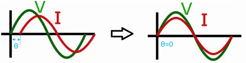
Figure 1. Reducing the phase difference between current and voltage
- HARDWARE IMPLEMENTATION
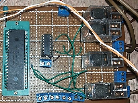
In this section, the implementation details on measurement devices used to capture the power parameters need to realize the power factor correction system will be demonstrated alongside with system PIC microcontroller.
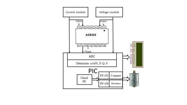
- PIC16F877A Microcontroller
One of the most popular microcontrollers is the PIC16F877A which is widely used due to its flexibility and low power consumption. It has 368 bytes of RAM and 3.5 kB of flash memory, 33 input/output pins, eight of which are analog-to-digital converters (ADCs), as shown in Figure 2. It has high timing precision because of its three timers [39]-[42]. It is used in this research to control the system and to convert the analog values of voltages and currents collected from modules into digital values, which are then combined with phase angle for power factor correction. The PIC microcontroller device is programmed using C++ language.

Figure 2. Integrated circuit for PIC16F877A microcontroller
- Analog Voltage Module
The voltage module is used to measure load voltage and is connected to the microcontroller as an analog input. Figure 3 shows the design of the voltage circuit module, which consists of a 220/10V voltage transformer, a LED indicator, and a variable resistor that acts as a voltage divider. Its main function is to provide the appropriate input voltage to the PIC microcontroller. The voltage module is connected to pin 2 as an analog input of the PIC microcontroller. Whereas pins RA0 to RA5 (pins 2 to 7) and RE0 and RE1 (pins 9 and 10) are analog-to-digital converter pins and are used as analog inputs.
Figure 3. Analog voltage module
- Analog Current Module
The current module is used to measure load current and is connected to the microcontroller as an analog input. The current circuit module is shown as in Figure 4. This module consists of a LED indicator, a resistance that measures current proportional to voltage, and a 100A/30mA current transformer. Its main function is to reduce the current to suit PIC microcontroller input limits. The LM741 Op-Amp amplifies the weak current signal supplied by the current transformer as a dual stage of the inverter amplifier. The overall gain is adjusted so that the maximum expected load current corresponds to a voltage within the ADC input range. Although the LM741 is a general-purpose op-amp, it was selected for the prototype because of its availability and cost. The current module is connected to pin 3 as an analog input of the PIC microcontroller
Figure 4. Analog current module
- Phase Detector Module
The phase detector module uses the AD8302 integrated circuit, as shown in Figure 5. This integrated circuit provides improved sensitivity and accuracy for calculating the phase angle ( ) between voltage and current. This module produces a proportional analog voltage of 10mV/degree after comparing two input voltages (one from the voltage module and the other from the current module). The PIC microcontroller converts this voltage to a digital value using an analog-to-digital converter. The phase detector module is connected to pin 4 as an analog input of the PIC microcontroller.
Figure 5. Phase detector module with AD8302 IC
- Opto-Isolation Module
This module is used as the input for the phase detector module, supplying it with a regulated constant voltage of 5V to protect the AD8302 integrated circuit against voltage fluctuations, especially over-voltages. The optical isolation module consists of two PC817 optocouplers with appropriate resistors, as shown in Figure 6. The PC817 is a single-chip package that includes a phototransistor and a LED. The LED generates infrared light when an electrical signal is applied to it, and the phototransistor absorbs this light to produce a 5V electrical output. This provides good protection for sensitive integrated circuits from noise or overvoltage by electrically isolating the inputs and outputs [43]-[45].
Figure 6. Opto-isolation module
- Output Units
- LCD LM016L is used to display current, voltage, phase angle and PF values. It is connected to (Pin 19 - Pin 22 and Pin 27 - Pin 30) of the PIC microcontroller outputs.
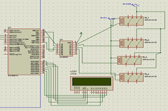
- Relay output unit that is an electromagnetic switch with three terminals. One terminal is connected to the 12V supply from the ULN2003A, and the other terminal is connected to ground, as shown in Figure 7. It is activated when a 5V signal is received from the PIC output. The third terminal is connected to a contactor. The ULN2003A connects to one of the PIC outputs (pins 33, 34, 37, and 40), which provides 5V to activate the relay. The ULN2003A is utilized to connect the relay to the microcontroller since the relay requires more current than the microcontroller's output. An internal diode is used to protect the ULN2003A from sparks generated by the relay.
- Contactor output units are used as a second stage to connect and disconnect three-phase delta-connected capacitors that receive activation signals from relay output units.
- Capacitor bank unit that is a three-phase capacitor bank connected in delta connection is used to adjust the reactive power compensated into the grid according to the required value for power factor correction. The microcontroller connects and disconnects the capacitor bank using contactors.
| 
|
Figure 7. Relay output units
- Power Supply
The XL4016 Buck converter is used to power the microcontroller, current and voltage modules, and output relay units. The voltage and current requirements for the microcontroller are approximately 5V 10mA, while the analog current module requires 12V 5mA, the phase detector module requires 5V 3mA, the opto-isolator module requires 5V 20mA, and the relay units requires 12V. The Buck converter changes the voltage from 220V to 12V DC, and then the regulator circuit steps it down to 5V DC. This converter boasts a high efficiency of up to 95%, which helps avoid overheating by lowering the amount of heat produced. Its dual heat sink design ensures that the system stays cool and functional for longer periods of time by extending battery life and reducing heat loss. Additionally, long-term dependability and steady performance are built into its design [46].
- METHODOLOGY
Figure 8 shows a flowchart of a PFC system that illustrates the detailed steps taken by the system controller to achieve a correction process for any power factor. The microcontroller initializes the peripherals, sets up timers, and configures the analog-to-digital converters. After the peripherals are initialized, the current and voltage modules capture the current and voltage as analog values using current and voltage transformers. The AD8302 phase detector checks zero-crossing points and compares the phase difference between voltage and current. The built-in phase detector within the AD8302 generates a DC analog voltage at the output terminal of approximately 10 mV per degree of phase difference. The PIC microcontroller reads the voltage, current, and phase difference via the analog input, then converts them to digital voltage, current, and phase angle using an ADC. It then calculates the apparent power, real power, reactive power, and power factor. Where, the apparent power S is ( ), VA. The real power P is (
 ), W. The reactive power Q is (
 ), VAR. While the power factor PF is (
 ).
).
The most important operation here is checking the power factor value, which is the cosine of the phase angle ( ). If the power factor value is between 0.92 and 0.98, the controller continues to monitor the system without taking any action. If the power factor value is less than 0.92, the system connects the first unit of the capacitor bank, rereads the inputs, and calculates the power factor. As long as the power factor value remains below 0.92, the controller continues to add another capacitor bank unit and re-evaluate. If the power factor value increases above 0.98, the microcontroller disconnects the final capacitor bank unit connected in the final step.
To avoid large fluctuations resulting from the speed of disconnecting and connecting the capacitors, a time delay of 5 seconds was added before any disconnection or connection operation was performed. The LCD displays both the read values ( ) and calculated values (
 ) sequentially, one value at a time, and the user can switch between them by pressing a push button. This continuous loop process improves power efficiency and guarantees real-time power factor correction monitoring.
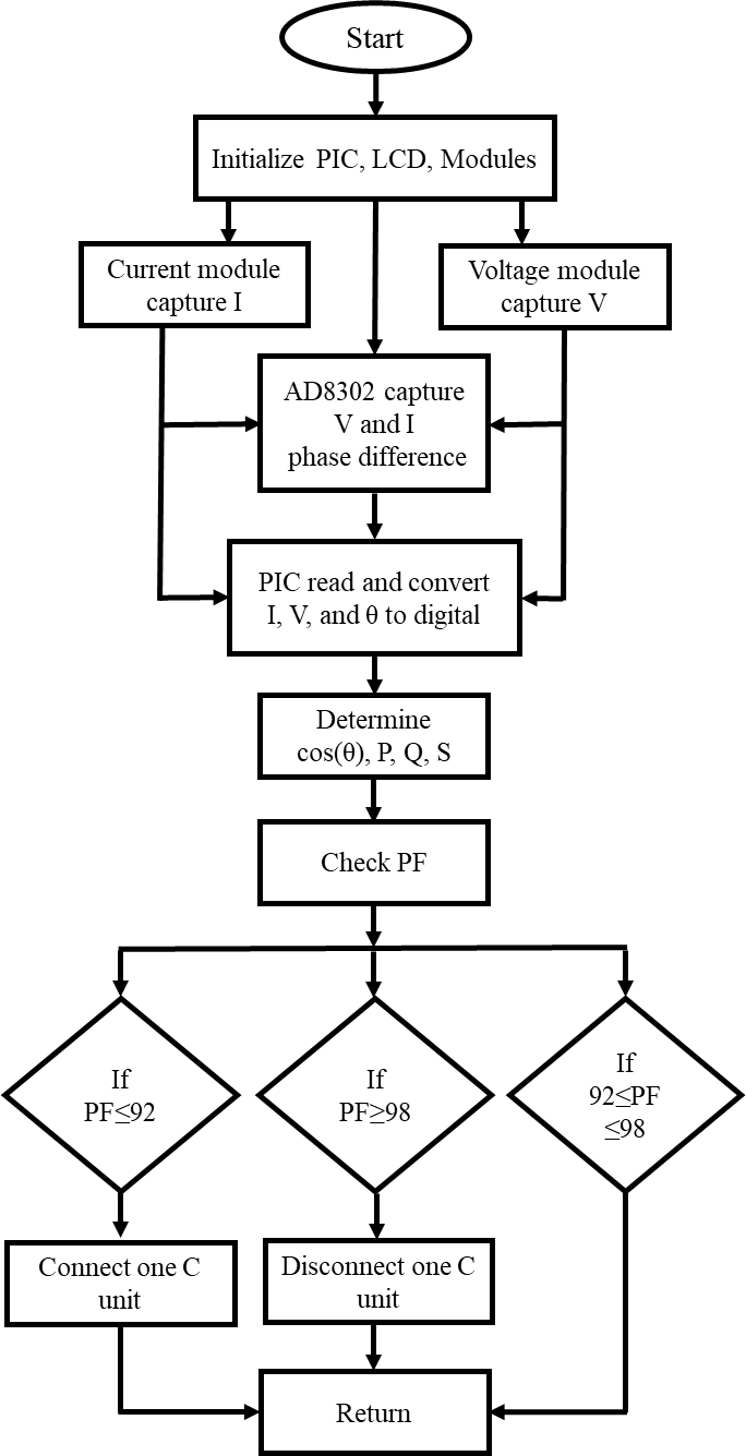
Figure 8. Flowchart of the proposed system
- RESULTS AND DISCUSSION
To verify the system's effectiveness, several experiments were conducted on each module individually. The effectiveness of the voltage module was first tested. Multiple readings of the load voltage values were taken using a voltmeter and an analog voltage module through PIC microcontroller. The results are shown in Figure 9. These experiments revealed that the percentage error of the voltage module's readings compared to the voltmeter readings was 1.32%.
The effectiveness of the analog current module was then tested. Multiple readings of the load current values were taken using an ammeter and an analogue current module through PIC microcontroller, and the results were shown in Figure 10. These experiments revealed that the percentage error of the current module's readings compared to the ammeter readings was 3.02%.
The effectiveness of reading input values from analog input modules, calculating power types and power factor results was then tested. In this test, there are four inductive loads, all rated at 1kW and 220V. The first has a power factor of 0.92, the second 0.88, the third 0.85, and the fourth 0.82. It was found that the measured and calculated values using the proposed system for the loads individually were as shown in Table 1.
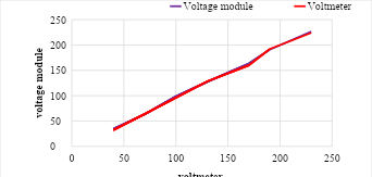
Figure 9. Voltage measurement using a voltmeter versus analog voltage module
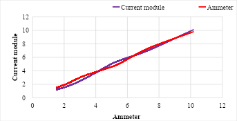
Figure 10. Current measurement using an Ammeter versus analog current module
Table 1. The measured and calculated values by the proposed system for the loads used
Load | V (V) | I (A) | θ (degree) | S (VA) | P (W) | Q (VAR) | PF |
1 | 222 | 4.72 | 23.07 | 1086 | 1000 | 425 | 0.92 |
2 | 221 | 4.93 | 28.36 | 1136 | 1000 | 539 | 0.88 |
3 | 223 | 5.1 | 31.79 | 1176 | 1000 | 619 | 0.85 |
4 | 222 | 5.3 | 34.91 | 1219 | 1000 | 698 | 0.82 |
The effectiveness of the power factor correction was then tested on the four combined inductive loads mentioned, and the measured and calculated values are shown in Table 2. The power factor before the controller added any capacitors was 0.865. Now the controller added the first unit of capacitors, so the power factor became 0.884. Thus, the controller continued adding units of capacitors until the power factor reached 0.935. The load current was reduced by 7% from 19.9A to 18.5A, while the load reactive power of was decrease by 35% from 23.1kVAR to 15.1kVAR.
The experimental results show that the power factor correction for this system ranges between 0.92 and 0.98. If the power factor falls below this limit, a capacitor is added; if the power factor rises over that limit, the last added capacitor unit is disconnected. Therefore, while many studies have focused on calculating reactive power and capacitor values, this study simplifies the process without overcorrection. Table 3 compares the proposed power factor correction system with earlier methods documented in the literature, all of them involve capacitor bank technology.
Table 2. The measured and calculated values during the power factor correction process
Loads + Capacitors | V (V) | I (A) | (degree) | S (VA) | P (W) | Q (VAR) | PF |
4 loads | 224 | 19.9 | 29.9 | 4619 | 4000 | 2310 | 0.865 |
4 loads +1C | 222 | 19.5 | 27.8 | 4522 | 4000 | 2110 | 0.884 |
4 loads +2C | 221 | 19.2 | 25.5 | 4432 | 4000 | 1910 | 0.902 |
4 loads +3C | 223 | 18.9 | 23.1 | 4350 | 4000 | 1710 | 0.919 |
4 loads +4C | 222 | 18.5 | 20.6 | 4275 | 4000 | 1510 | 0.935 |
Table 3. Comparison of the proposed system with other PFC systems using capacitor bank technology.
Ref | Controller and Technique | Strengths | Limitations |
[38] | Arduino uses the Emonlib library to precisely monitoring power, calculating power parameters from voltage and current sensors, and then automatically switching capacitor banks via relays based on the required KVAR value. | Combines PFC and monitoring for high-precision power evaluation using the Emonlib library. | PFC is affected by distortions, in addition to some complexities in programming. |
[47] | Using Arduino and zero detecting circuits for single and three-phase loads. | Modified voltage and current detection circuits for improved accuracy. | The effects of overcorrection and ways to avoid them were not discussed. |
[48] | Arduino controls TRIACs to connect and disconnect capacitors | TRIACs makes the switching process faster than relays | Inflexible because it does not take into account changes in real-time load |
[49] | Controller are not specified. Thyristors control capacitors with high response time | Suitable for varying loads due to the fast response time provided by thyristors | Using thyristors is expensive compared to relays. Requires specialized expertise for installation and maintenance. Overcorrection is not considered to avoid a leading power factor |
[50] | Combining a PI controller with a termination algorithm achieves high accuracy through a closed-loop control algorithm with precise reactive compensation capacitor connect/disconnect. | The PI controller ensures that the power factor remains stable, and the termination algorithm prevents overcorrection by precisely adjusting the number of capacitors. | Fine tuning of the PI controller parameters is required and becomes complex to implement. |
[51] | The 8051 microcontroller uses a detailed algorithm to measure the phase difference between current and voltage and then switch the appropriate capacitors for PFC. | Provides detailed calculations for capacitors and tables for selecting them based on the target current and power factor. | The microcontroller is outmoded, basic, and responds slowly. Additionally, it lacks flexibility. |
[52] | MATLAB Simulink uses an automatic control algorithm to correct the power factor by switching capacitor banks. | Reduces the probability of overcorrection by separating the capacitors into multiple stages. | MATLAB/Simulink experience required for implementation |
Proposed system | PIC microprocessor connects and disconnects capacitors using relays and contactors, and it measures and corrects power factor using analog current, voltage, and phase detector modules. | Analog modules are used. Furthermore, no overcorrection occurs. The proposed system evaluates the PF, and if it falls below 0.92, it connects the capacitors. If it exceeds 0.98, it disconnects the final stage of capacitors. | Slower response than TRIACs, suitable for small scale applications |
- CONCLUSIONS
The power factor correction system for capacitor bank technology is designed based on a PIC microcontroller, where load measurements of current, voltage, and phase difference between them are obtained from analog modules. The microcontroller receives these readings through its analog inputs, converts them to digital, calculates the power values, and determines the power factor. If the power factor is low, the microcontroller begins adding capacitors and continues monitoring the power factor until it reaches 0.92. If the power factor reaches 0.98, the microcontroller undoes the last capacitor connection and continues monitoring the load and power factor. Based on all previous experiments on a 4 kW inductive load set, it is clear that the system is capable of reading values from analog inputs, calculating power and power factor values, and performing a power factor correction. The system corrected the power factor from 0.865 to 0.935, resulting in a 7% reduction in load current and a 35% reduction in reactive load power. This demonstrates the feasibility of the proposed approach and its ability to improve the stability of the electrical grid in small-scale applications.
DECLARATION
Sustainable Development Goals
Affordable and Clean Energy (SDG 7), Industry, Innovation and Infrastructure (SDG 9).
Author Contribution
All authors contributed equally to the main contributor to this paper. All authors read and approved the final paper.
Acknowledgement
The authors are grateful to Palestine Technical University - Kadoorie for their support to conduct this research.
Conflicts of Interest
The authors declare no conflict of interest.
REFERENCES
- C. M. Coman, A. Florescu, and C. D. Oancea, "Improving the efficiency and sustainability of power systems using distributed power factor correction methods," Sustainability (Switzerland), vol. 12, no. 8, pp. 1-20, 2020, p. 3134, 2020, https://doi.org/10.3390/su12083134.
- I. Surya and J. Kustija, "Dashboard for Industrial Load Control and Remote Power Factor Correction Based on Adafruit's MQTT," Buletin Ilmiah Sarjana Teknik Elektro, vol. 5, no. 1, pp. 76-85, 2023, https://doi.org/10.12928/biste.v5i1.7494.
- W. A. Salah, A. B. Musa, B. A. Zneid, A. Abu Sneineh, and M. S. Jadin, "Implementation of virtual instruments as a power quality analysis tool," Journal of Low Power Electronics, vol. 12, no. 2, pp. 83-90, 2016, https://doi.org/10.1166/jolpe.2016.1435.
- G. Adedayo Ajenikoko, O. Adigun, and A. Olayinka Rafiu, "Control Techniques and Power Factor Correction Methods: A Review," Journal of Engineering Research and Reports, vol. 2, no. 1, pp. 1-13, 2018, https://doi.org/10.9734/jerr/2018/v2i19883.
- A. A. Al-Muhanna, M. A. Abido, and F. S. Al-Ismail, "Assessing Impact of Optimally Placed Power Factor Correction Capacitors Reckoning Transient Switching Events," Arabian Journal for Science and Engineering, vol. 46, no. 2, pp. 1269-1277, 2021, https://doi.org/10.1007/s13369-020-04996-4.
- C. M. Coman, A. Florescu, and C. D. Oancea, "Improving the Efficiency and Sustainability of Power Systems Using Distributed Power Factor Correction Methods," Sustainability, vol. 12, no. 8, 2020, https://doi.org/10.3390/su12083134.
- A. Quiroga, J. Bayona, and H. Espitia, "Review of Converter Circuits with Power Factor Correction," Technologies, vol. 13, no. 6, 2020, https://doi.org/10.3390/technologies13060221.
- W. A. Salah, M. Abuhelwa, M. Elnaggar, Y. F. Nassar, H. J. El-Khozondar, and M. J. K. Bashir, "Assessment of waste to energy approaches to compensate for the shortage in energy supply in Gaza, Palestine," Biofuels, Bioproducts and Biorefining, vol. 19, no. 6, pp. 2318-2332, 2025, https://doi.org/10.1002/bbb.70027.
- M. Salem, A. Elmabruk, M. Irhouma, and I. Mangir, "Assessment of Wind Energy Potential in Western Mountain: Nalut and Yefren as Case Study," Wadi Alshatti University Journal of Pure and Applied Sciences, vol. 3, no. 1, pp. 35-42, 2025, https://doi.org/10.63318/waujpasv3i1_7.
- A. Elmabruk, M. Salem, M. Khaleel, and A. Mansour, "Prediction of Wind Energy Potential in Tajoura and Mislata Cities," Wadi Alshatti University Journal of Pure and Applied Sciences, vol. 3, no. 2, pp. 125-131, 2025, https://doi.org/10.63318/waujpasv3i2_17.
- I. Imbayah, A. Almiladi, M. AlKarghali, A. R. Oraibi, Y. Adraider, and H. Meshreghi, "Remote Climate Monitoring Through the Utilization of Solar Energy for Meteorological Systems," University of Zawia Journal of Engineering Sciences and Technology, vol. 3, no. 1, pp. 156-170, 2025, https://doi.org/10.26629/uzjest.2025.13.
- Y. F. Nassar et al., "Estimation of CO2 emission within Libya's electricity generation sector," Next Research, vol. 2, no. 3, p. 100567, 2025, https://doi.org/10.1016/j.nexres.2025.100567.
- S. Saeed and T. Siraj, "Global Renewable Energy Infrastructure: Pathways to Carbon Neutrality and Sustainability," Solar Energy and Sustainable Development Journal, vol. 13, no. 2, pp. 183-203, 2024, https://doi.org/10.51646/jsesd.v13i2.243.
- E. Hakizimana, H. Umuhoza, E. Manishimwe, and V. Kayibanda, "Economic Optimization of Grid-Connected Photovoltaic Solar Systems in Industrial Energy: Case Study SULFO Ltd - Rwanda," Solar Energy and Sustainable Development Journal, vol. 13, no. 2, pp. 204-229, 2024, https://doi.org/10.51646/jsesd.v13i2.242.
- M. Nyasapoh et al., "Navigating Renewable Energy Transition Challenges for a Sustainable Energy Future in Ghana," Solar Energy and Sustainable Development Journal, vol. 14, no. 1, pp. 237-257, 2025, https://doi.org/10.51646/jsesd.v14i1.479.
- C. Kumar, M. Lakshmanan, S. Jaisiva, K. Prabaakaran, S. Barua, and H. H. Fayek, "Reactive power control in renewable rich power grids: A literature review," vol. 17, no. 5, pp. 1303-1327, 2023, https://doi.org/10.1049/rpg2.12674.
- C. Adragna, A. Bianco, G. Gritti, and M. Sucameli, "State-of-the-Art Power Factor Correction: An Industry Perspective," Encyclopedia, vol. 4, no. 3, pp. 1324-1354, 2024, https://doi.org/10.3390/encyclopedia4030087.
- D. J. Dullius et al., "Analysis of Financial Penalties for Low Power Factor in Distribution Systems With High Penetration of Photovoltaics," IEEE Access, vol. 12, pp. 169102-169123, 2024, https://doi.org/10.1109/ACCESS.2024.3493379.
- M. M. A. Aziz, E. E. A. El-Zahab, and A. F. Zobaa, "Power factor and your electrical utility bill in Egypt," IEEE Transactions on Power Delivery, vol. 18, no. 4, pp. 1567-1568, 2003, https://doi.org/10.1109/TPWRD.2003.817535.
- S. Chowdhury, E. Gurpinar and B. Ozpineci, "Capacitor Technologies: Characterization, Selection, and Packaging for Next-Generation Power Electronics Applications," in IEEE Transactions on Transportation Electrification, vol. 8, no. 2, pp. 2710-2720, 2022, https://doi.org/10.1109/TTE.2021.3139806.
- Q. -H. Wu, Y. Lin, C. Hong, Y. Su, T. Wen and Y. Liu, "Transient Stability Analysis of Large-scale Power Systems: A Survey," in CSEE Journal of Power and Energy Systems, vol. 9, no. 4, pp. 1284-1300, 2023, https://doi.org/10.17775/CSEEJPES.2022.07110.
- A. Symonds and M. Laylabadi, "Cycloconverter Drives in Mining Applications: A Typical Industrial System Is Analyzed and the Impact of Harmonic Filtering Considered," in IEEE Industry Applications Magazine, vol. 21, no. 6, pp. 36-46, 2015, https://doi.org/10.1109/MIAS.2014.2345805.
- H. Soleimani, D. Habibi, M. Ghahramani, and A. Aziz, "Strengthening Power Systems for Net Zero: A Review of the Role of Synchronous Condensers and Emerging Challenges," Energies, vol. 17, no. 13, p. 3291, 2024, https://doi.org/10.3390/en17133291.
- I. Bashir, A. H. Bhat, and S. Ahmad, "A review on soft switched PFC boost converter for efficient lowering of switching losses," Electric Power Systems Research, vol. 242, p. 111430, 2025, https://doi.org/10.1016/j.epsr.2025.111430.
- A. Šešok and I. Pavić, "SVC Control Strategy for Transient Stability Improvement of Multimachine Power System," Energies, vol. 17, no. 17, p. 4224, 2024, https://doi.org/10.3390/en17174224.
- I. Benhabsa, R. Kouadri, L. Slimani, and S. Mouassa, "Improving power system performance by integrating TCSC and SVC devices in the presence of stochastic renewable energy generators," Wind Engineering, p. 0309524X241307313, 2025, https://doi.org/10.1177/0309524X241307313.
- S. Raj and B. Bhattacharyya, "Optimal placement of TCSC and SVC for reactive power planning using Whale optimization algorithm," Swarm and Evolutionary Computation, vol. 40, pp. 131-143, 2018, https://doi.org/10.1016/j.swevo.2017.12.008.
- V. K. Gupta, S. K. Mishra, and R. Babu, "FACTS placement for reactive power planning with weak node constraints using an improved symbiotic search algorithm," Transactions on Energy Systems and Engineering Applications, vol. 4, no. 2, p. 524, 2023, https://doi.org/10.32397/tesea.vol4.n2.524.
- V. K. Gupta and R. Babu, "Reactive power planning problem considering multiple type of FACTS in power systems," International Journal of System Assurance Engineering and Management, vol. 13, no. 4, pp. 1885-1894, 2022, https://doi.org/10.1007/s13198-021-01588-9.
- A. Abaza, R. A. El-Sehiemy, M. Said, R. M. Ghoniem, and A. F. Barakat, "Implementation of an Electronically Based Active Power Filter Associated with a Digital Controller for Harmonics Elimination and Power Factor Correction," Electronics (Switzerland), vol. 11, no. 14, p. 2205, 2022, https://doi.org/10.3390/electronics11142205.
- R. M. Milasi, A. F. Lynch, and Y. Li, "Adaptive control of an active power filter for harmonic suppression and power factor correction," International Journal of Dynamics and Control, vol. 10, no. 2, pp. 473-482, 2022, https://doi.org/10.1007/s40435-021-00825-0.
- Y. Asadi, M. Eskandari, M. Mansouri, S. Chaharmahali, M. H. Moradi, and M. S. Tahriri, "Adaptive Neural Network for a Stabilizing Shunt Active Power Filter in Distorted Weak Grids," Applied Sciences, vol. 12, no. 16, 2022, https://doi.org/10.3390/app12168060.
- C. Y. Chan, "Power Factor Correction Based on Adaptive Modified Current-Mode Control Approach," IEEE Transactions on Circuits and Systems II: Express Briefs, vol. 69, no. 3, pp. 1462-1466, 2022, https://doi.org/10.1109/TCSII.2021.3119705.
- M. Dreidy, W. salah, and M. Safarini, "Development of an Optimal Control Strategy of Three Phase Power Factor Correction System," Solar Energy and Sustainable Development Journal, vol. 14, no. 2, pp. 74-96, 09/09 2025, https://doi.org/10.51646/jsesd.v14i2.660.
- V. Aviña-Corral, J. Rangel-Magdaleno and J. Hernandez-Perez, "63-Level Asymmetric Capacitor an Inductor Bank without Discharge Resistors and Reduced Transients," 2023 IEEE International Autumn Meeting on Power, Electronics and Computing (ROPEC), pp. 1-6, 2023, https://doi.org/10.1109/ROPEC58757.2023.10409412.
- M. B. Gawande, S. D. Bangar, N. M. Wagh and T. B. Bele, "Power Factor Correction using PLC," 2024 International Conference on Knowledge Engineering and Communication Systems (ICKECS), pp. 1-5, 2024, https://doi.org/10.1109/ICKECS61492.2024.10616624.
- M. Ali, F. Rashid, and S. Rasheed, "Power factor improvement for a three-phase system using reactive power compensation," Indonesian Journal of Electrical Engineering and Computer Science, vol. 24, no. 2, pp. 715-727, 2021, https://doi.org/10.11591/ijeecs.v24.i2.pp715-727.
- Y. Kabir, Y. M. Mohsin, and M. M. Khan, "Automated power factor correction and energy monitoring system," in Proceedings of the 2017 2nd IEEE International Conference on Electrical, Computer and Communication Technologies, ICECCT 2017, 2017, https://doi.org/10.1109/ICECCT.2017.8117969.
- E. H. Currie, "Introduction to Embedded System," in Mixed-Signal Embedded Systems Design: A Hands-on Guide to the Cypress PSoC, pp. 1-34, 2021, https://doi.org/10.1007/978-3-030-70312-7_1.
- A. Radovici and I. Culic, "Embedded Systems and Architectures," in Getting Started with Secure Embedded Systems: Developing IoT Systems for micro:bit and Raspberry Pi Pico Using Rust and Tock, pp. 1-26, 2022, https://doi.org/10.1007/978-1-4842-7789-8_1.
- W. A. Salah, B. A. Zneid, A. Abu_al_aish, and M. Nofal, "Development of Smart and Portable Controllable Syringe Pump System for Medical Applications," Journal of Engineering and Technological Sciences, vol. 55, no. 3, pp. 300-312, 2023, https://doi.org/10.5614/j.eng.technol.sci.2023.55.3.7.
- A. Abu Sneineh and W. A. Salah, "Design and implementation of an automatically aligned solar tracking system," International Journal of Power Electronics and Drive Systems, vol. 10, no. 4, pp. 2055-2064, 2019, https://doi.org/10.11591/ijpeds.v10.i4.pp2055-2064.
- V. Gupta, M. Sharma, R. K. Pachauri, and K. N. D. Babu, "A Low-Cost Real-Time IOT Enabled Data Acquisition System for Monitoring of PV System," Energy Sources, Part A: Recovery, Utilization, and Environmental Effects, vol. 43, no. 20, pp. 2529-2543, 2021, https://doi.org/10.1080/15567036.2020.1844351.
- Q. Xiang, Y. Hu, Y. Shao, and X. Ye, "Integrated Design of a Multi-Channel Cyclic Data Acquisition Module Circuit," in 2023 3rd International Conference on Electrical Engineering and Mechatronics Technology (ICEEMT), pp. 111-115, 2023, https://doi.org/10.1109/ICEEMT59522.2023.10263228.
- A. R. Syafriansyah¹ and R. A. Fatekha, "Prototype of Data Acquisition Module," in Proceedings of the 7th International Conference on Applied Engineering (ICAE 2024), vol. 251, p. 287, 2024, https://doi.org/10.2991/978-94-6463-620-8_22.
- M. Matejček and M. Šostronek, "Microcontroller Based Evaluation of Voltage Regulators Efficiency and Their Noise Performance Estimation by Fast Allan Variance Method," Electronics, vol. 13, no. 11, p. 2144, 2024, https://doi.org/10.3390/electronics13112144.
- M. S. Rahman, A. Memy, M. A. Mahmud, and S. Siddique, "Automatic Power Factor Measurement and Improvement Using Capacitor Bank," in 2022 IEEE International Power and Renewable Energy Conference, IPRECON 2022, 2022, https://doi.org/10.1109/IPRECON55716.2022.10059553.
- M. S. Rahman, A. Memy, M. A. Mahmud and S. Siddique, "Automatic Power Factor Measurement And Improvement Using Capacitor Bank," 2022 IEEE International Power and Renewable Energy Conference (IPRECON), pp. 1-6, 2022, https://doi.org/10.1109/IPRECON55716.2022.10059553.
- A. G. Shende, S. W. Khubalkar, and P. Vaidya, "Hardware Implementation of Automatic Power Factor Correction Unit for Industry," in Journal of Physics: Conference Series, vol. 2089, 2021, https://doi.org/10.1088/1742-6596/2089/1/012032.
- M. Y. Naqash, Z. J. E. Rashid, Control, and C. Engineering, "PI controller based automatic power factor correction (APFC) using capacitor bank," vol. 19, no. 1, pp. 40-48, 2023, https://doi.org/10.2478/ecce-2023-0006.
- D. J. Pandya et al., "Automatic Power Factor Compensation for Industrial Use to Minimize Penalty," 2023 6th International Conference on Contemporary Computing and Informatics (IC3I), pp. 2499-2504, 2023, https://doi.org/10.1109/IC3I59117.2023.10398095.
- M. Ayaz, S. M. H. Rizvi, and M. Akbar, "Dynamic Power Factor Correction in Industrial Systems: An Automated Capacitor Bank Control Approach," in 2023 2nd International Conference on Emerging Trends in Electrical, Control, and Telecommunication Engineering, ETECTE 2023 - Proceedings, 2023, https://doi.org/10.1109/ETECTE59617.2023.10396685.
AUTHOR BIOGRAPHY

| Anees Abu Sneineh     is currently an Associate Professor in Palestine Technical University-Kadoorie. He earned his PhD in Power Electronics and Electrical Drives Engineering and his MS in Mechatronics Engineering from Harbin Institute of Technology, China in 2007 and 2004, respectively. He received Best Research Award, Palestine Technical University-Kadoorie yearly since 2018-2020. His research interests are power electronics and drives, renewable energy systems, electrical machines and their automation, robotic and its applications, applied electronics, and smart systems. Dr. Abu Sneineh has published many papers in international journals and conferences. He can be contacted at enganees2002@yahoo.com is currently an Associate Professor in Palestine Technical University-Kadoorie. He earned his PhD in Power Electronics and Electrical Drives Engineering and his MS in Mechatronics Engineering from Harbin Institute of Technology, China in 2007 and 2004, respectively. He received Best Research Award, Palestine Technical University-Kadoorie yearly since 2018-2020. His research interests are power electronics and drives, renewable energy systems, electrical machines and their automation, robotic and its applications, applied electronics, and smart systems. Dr. Abu Sneineh has published many papers in international journals and conferences. He can be contacted at enganees2002@yahoo.com |
|
|

| Wael A. Salah is a full professor at the Electrical Engineering Department, Palestine Technical University-Kadoorie, Tulkarm, Palestine. Dr. Salah received his Ph.D and M.Sc degrees in Electrical and Electronic Engineering from Universiti Sains Malaysia (USM) in 2007 and 2012 respectively. Dr. Salah received a bachelor’s degree in electrical and computer engineering (ECE) from Palestine Polytechnic University (PPU) in 2001. He received the Excellent Publication Award “Saggar Sanjun” for the years 2009 and 2010 from Universiti Sains Malaysia. In addition, he received Best Research Award, Palestine Technical University-Kadoorie yearly since 2018-2024. His research interests include renewable energy, clean energy, energy management, energy utilization, energy efficiency, power electronics and electric drives. He has published more than 65 research papers in peer-reviewed reputed journals and conferences. Prof. Salah is a recognized board member for several international journals and conference proceedings in the field of electrical, electronics, energy and power engineering. He is also a recognized reviewer of highly distinguished journals published by: IEEE, Elsevier, and other well-known publishers. Dr. Wael is a senior member of the Institute of Electrical and Electronics Engineers (IEEE), US, a member of the Jordanian Engineers Association (JEA) and a member of Arab Engineers Association (AEA). More details on research and publications can be found on the professional networks profile: https://www.researchgate.net/profile/Wael-Salah-3. He can be contacted at w.salah@ptuk.edu.ps |
|
|

| Alfian Ma’arif (Member, IEEE) was born in Klaten, Central Java, Indonesia, in 1991. He received the bachelor’s degree from the Department of Electrical Engineering, Universitas Islam Indonesia, in 2014, and the master’s degree from the Department of Electrical Engineering, Universitas Gadjah Mada, in 2017. From 2017 to 2018, he was a Lecturer with the Department of Electrical Engineering Education, Universitas Negeri Yogyakarta. Since 2018, he has been a Lecturer with the Department of Electrical Engineering, Universitas Ahmad Dahlan. He is currently an Assistant Professor, since 2020. His research interest includes control systems. He is a member of IAENG and ASCEE. He is the Editor in Chief of International Journal of Robotics and Control Systems and the Managing Editor of the Journal of Robotics and Control (JRC). E-mail: alfianmaarif@ee.uad.ac.id |
Anees Abu Sneineh (Implementation of an Automatic Controlled Power Factor Correction System Utilizing Low-Cost Modules)