ISSN: 2685-9572 Buletin Ilmiah Sarjana Teknik Elektro
Vol. 8, No. 3, June 2026, pp. 868-886
Review-Simulation Model of Power Electronic Converters by Using MATLAB
Salam Waley Shneen 1, Suaad Makki Jiaad 2
1 Energy and Renewable Energies Technology Center, University of Technology–Iraq
2 College of Electromechanical Engineering, University of Technology–Iraq
ARTICLE INFORMATION |
| ABSTRACT |
Article History: Received 21 June 2025 Revised 26 October 2025 Accepted 25 June 2026 |
| 
Power electronics is known as one of the most important branches of electrical science or electrical engineering, focusing on the design of electronic circuits for control and conversion applications of electrical quantities between the input and output of electronic converters. Power electronics is linked to control (control systems) on the one hand and conversion (electrical energy conversion) on the other. Semiconductors (diodes, transistors, and thyristors) are used in power electronics construction. Industrial applications are one of the most important uses of power electronics. The use of power electronics in many fields provides improved energy use with a high level of efficiency, such as in renewable energies (such as solar panels and wind turbines), as well as electric vehicles and related industrial applications. Converters are named according to their function. Rectifiers convert alternating current (AC) to direct current (DC) in either single-phase or three-phase. Converters are constructed using semiconductors, including diodes, transistors, and thyristors. The number of electronic switches varies depending on the type of converter and is determined by the type of power source and the type of load connected to the converter's output. Another type of converter, called an inverter, works in the opposite direction to a rectifier, converting DC to alternating current in either single-phase or three-phase. To further understand converters, this review presents a literature review of power converters according to research contributions. The first research contribution includes an overview of the power electronics overview. The second research contribution identifies converter types, and the third identifies their applications. To further enhance knowledge, we use theoretical mathematical representations of these types of power converters and select simulation models using MATLAB to analyze their behavior through simulation results. Based on the results, appropriate conclusions can be drawn and contributions can be identified for future work. |
Keywords: Power Electronic Converter; DC/DC Converter; Inverter; AC/AC Converter; Rectifier |
Corresponding Author: Salam Waley Shneen, Energy and Renewable Energies Technology Center, University of Technology –Iraq. Email: salam.w.shneen@uotechnology.edu.iq |
This work is open access under a Creative Commons Attribution-Share Alike 4.0 
|
Document Citation: S. W. Shneen and S. M. Jiaad, “Review-Simulation Model of Power Electronic Converters by Using MATLAB,” Buletin Ilmiah Sarjana Teknik Elektro, vol. 8, no. 3, pp. 868-886, 2026, DOI: 10.12928/biste.v8i3.14047. |
INTRODUCTION
Efficiently converting and controlling energy requires continuous operation. Therefore, power electronics has become a branch of electrical engineering. It has emerged alongside modern technology as an advanced technology that encompasses numerous fields and has become part of many daily experiments, encompassing wide-ranging applications. Devices of all types, small and large, require technologies that ensure safe operation, meet the requirements, and provide the appropriate processors to meet the needs of diverse systems [1]-[5].
Semiconductors act as electronic switches, allowing or blocking current flow. First, diodes allow current in one direction and are made of silicon or germanium. The second type is the transistor, which includes the MOSFET. This type is suitable for low and medium power applications, characterized by its fast switching speed and high efficiency. Another type of switch is the IGBT transistor, suitable for high power applications, characterized by its high ability to handle both electrical current and voltage [6]-[10].
Rectifiers convert AC power to DC power, including single-phase and three-phase rectifiers. Rectifiers are used in many applications, such as charging batteries and operating a DC motor from an AC source using a rectifier-type converter. Inverters work in reverse, converting DC power to AC power, including single-phase and three-phase inverters. Inverters are used in many applications, such as electric cars powered by solar energy and AC motors. DC converters convert DC power from one level to a lower or higher level and are used in many applications, such as powering mobile phone systems, computers, and others. AC converters convert AC power from one level to another, lower or higher, in voltage or frequency, and are used in many applications, such as controlling motor speed and rotor position, among others [11]-[15].
Power electronics converts, regulates, and manages energy, as well as modulates waveforms. They are used in a wide range of applications, including electric and hybrid vehicles, smart grids, renewable energy systems, air conditioners, and more. They are also used in electronic drive (Automated Control), which involves the use of electronic circuits to automatically control and regulate the speed of an electric motor and the position of the rotor, as in robotics. Other important applications include battery charging and connecting batteries to power sources, the grid, and loads, as in electric vehicles and others [16]-[20].
Electrical power systems are connected through the main grid as an energy source, in addition to other sources that may be connected to the grid or may be isolated, including renewable energy systems. Sources vary in type, including alternating current (AC) and direct current (DC). Loads also vary, as they are AC or DC loads. Electrical quantities vary depending on the type of source, which may not match the load requirements. Therefore, converters may be required to provide the required quantity and type to cover the load requirements. Converters are connected to a fixed quantity and provide a variable output that can be controlled to achieve output according to load requirements. They can also regulate and control the speed and position of the rotating member of the motor, which is used to provide motion in many applications [21]-[25].
Power electronics has many applications, the first of which is power conversion, which is considered one of the main applications for converting energy from one form to another, such as converting alternating current to direct current. This type is called a rectifier, as in wind power generation systems. The second type is a DC-DC converter, which is also used in wind power systems. The converter output can be controlled with changes in wind speed, and the output is constant, as the conversion voltage is compatible with the grid. In electric vehicle applications, converters of this type are also used and connected to the electric vehicle battery. They can be powered by an AC or DC motor, and depending on the need, a suitable converter is used. Another application is controlling these motors, which can be operated by industrial robots according to automation, which can control the rotational speed of these motors, which provides the required movement at the appropriate time to perform the appropriate function, as well as controlling the position of the rotating member of these motors. It is characterized by the fact that the converter works to improve efficiency and reduce energy consumption. It is used in lighting systems, which provides the ability to increase or decrease the brightness of LED lights, which makes them work more efficiently in addition to saving energy consumption. It also operates devices in many home and consumer applications, in addition to mobile phones and computers, which require the regulation of electrical quantities (voltage and current) to operate safely [26]-[30].
Power electronic converters are widely used in many fields and applications, making them a topic of great interest. They are classified according to the type of input and output power: DC/DC converter, DC/AC converter, AC/AC converter, and AC/DC converter. Researchers are interested in one or more converters, some of them are interested in the first type, which is a DC-DC step-up converter that converts a constant value to a variable value. This converter can be used to operate a DC motor with the ability to change and control its rotation speed. Other researchers have presented their studies on the same type in another application, such as battery charging systems using a step-down DC-DC converter. Still others have presented the remaining types, with their different names and functions. The current review presents four types of Power electronic converters, their various applications, and diverse power sources. The study included constructing simulation models for each type to identify the components of these systems and analyzing the system behavior for each type. The methodology was identified through previous studies, in addition to conducting verification tests using simulation models (MATLAB) for this study, simulations are based on theoretical models. The review aims to establish a foundation and methodology for specialists, including researchers, students, and engineers, to learn about the types of Power electronic converters and their working mechanisms [31]-[35].
The researchers of this review present a simulation model for each converter with default values for the converter input. The resulting output can be verified and compared with the standard values, which can be calculated theoretically and mathematically. The first type of converter included an inverter in both single-phase and three-phase configurations. A second simulation modeled a rectifier in both single-phase and three-phase configurations. The other two types were simulated in their step-up and step-down DC-DC configurations. Finally, a simulation model was constructed for a single-phase and three-phase AC-DC converter [36]-[40].
METHODOLOGY OF POWER ELECTRONIC CONVERTER
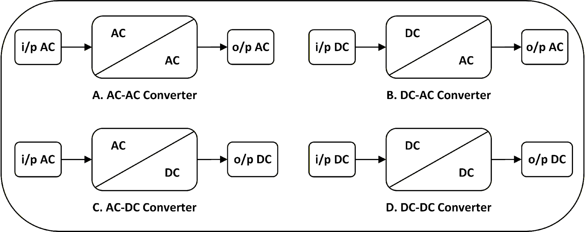
This section includes four types (Figure 1), the first an AC-AC converter identifies a type of electronic converter, which is an alternating current converter to alternating current. It is classified into single-phase and three-phase converters. The second a DC-AC converter identifies a type of electronic converter, which is a direct current converter to alternating current. It is classified into single-phase and three-phase inverters. The third DC-AC converter) identifies a type of electronic converter, which is a direct current converter to alternating current. It is classified into single-phase and three-phase rectifiers. The fourth a DC-DC converter identifies a type of electronic converter, which is a direct current converter to direct current. It is classified into step-up converter and step-down converter [41]-[45].
Figure 1. Schematic of a power electronic converter types
AC-DC converter (rectifier)
A rectifier is a type of power converter. This converter converts alternating voltage to direct voltage, which can be used to power DC loads, such as operating a DC motor. It can also be used with storage units, such as charging batteries. This review covers single-phase and three-phase rectifiers. These types are presented in two varieties: half-wave and full-wave. The most common types of rectifiers are those that use diode rectifiers, which are called pan-controlled rectifiers, while those that use thyristors or transistors are called control rectifiers. The present review presents simulation models of single-phase (Figure 2) and three-phase (Figure 3) rectifiers with resistive loads to study and analyze the behavior of the rectifier in open-loop mode, i.e. without using control systems, for comparison with theoretical results. The study demonstrated the effectiveness of the models through simulation results and comparison with theoretical calculations. It also demonstrated the feasibility of constructing and operating these types and their use in many different fields and applications [46]-[50].
Mathematical equation of single-phase rectifier as show bellow:
| 
| (1) |
| 
| (2) |
| 
| (3) |
| 
| (4) |
| 
| (5) |
| 
| (6) |
| 
| (7) |
| 
| (8) |
| 
| (9) |
| 
| (10) |
| 
| (11) |
| 
| (12) |
Figure 2. Sample of circuits for single phase rectifier (a)Single phase half wave rectifier by diode, (b) Single phase half wave rectifier by thyristor, (c) Single phase full wave rectifier by diode (d) Single phase full wave rectifier by thyristor
Mathematical equation of three-phase rectifier as show bellow:
Figure 3. Sample of circuits for three phase rectifiers (a) Three phase half wave rectifier by diode, (b) Three phase half wave rectifier by thyristor, (c) Three phase full wave rectifier by diode, (d)Three phase full wave rectifier by thyristor
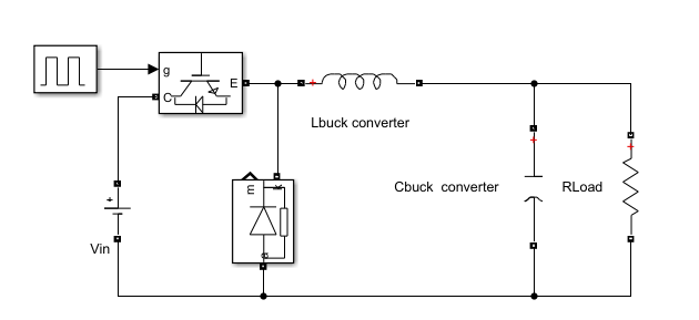
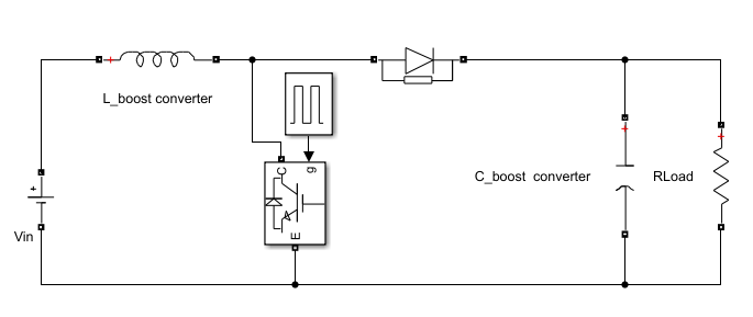
Dc-Dc Converter
Electronic power converter circuits work to convert the input voltage of the electronic converter into a voltage at a smaller or greater rate at the output of the electronic converter. The Dc-Dc converter is a direct current converter with a fixed value at the input that is regulated at the output of the converter as needed according to the design of the converter. The converter is DC. There are three types of Dc converters: the first is a voltage raiser and works to increase the value of the input voltage to the converter and is called Boost Converter (Figure 4(a)). The second type works to reduce the voltage entering the converter and is called a Buck Converter (Figure 4(b)). There is a third type that raises the voltage and reduces the voltage and is called a Boost-Buck Converter [51]-[55]. DC-DC converter, another type uses a DC source with a DC-DC converter with a fixed input and variable output, controlled using PWM or various control units. Semiconductors (diodes, transistors (MOSFETs), IPGTs, and thyristors) are employed as active components, in addition to passive components such as resistors, inductors, and capacitors, which can be used to construct models of various types of transformers, including step-up transformers and step-down transformers. Converters, including DC to DC, are used when the supply is from a constant-voltage power source and the converter outputs a variable-voltage DC. These can be sourced from solar energy, a battery, a DC microgrid, or a DC generator connected to a wind turbine [56]-[60].
| 
| (16) |
| 
| (17) |
|
(a) |
|
(b) |
Figure 4. Sample of circuits for DC-DC converter (a) Buck converter, (b) Boost converter
AC-AC Converter
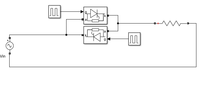
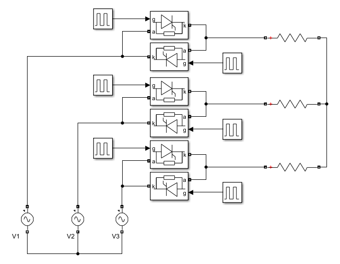
AC-AC converter, this converter converts a fixed AC quantity such as voltage and frequency into a variable AC quantity that can be controlled to increase or decrease the voltage or frequency (Figure 5). They are classified into single-phase and three-phase converters according to the type of power supply. A number of electronic switches are used to build the electronic converter. The converter consists of two terminals: the input terminal and the output terminal. The first terminal is connected to the constant AC power source, while the second terminal is connected to the load to be supplied with a variable AC quantity. One of the most important and common loads for which this type of transformer is used is controlling the rotational speed of single-phase and three-phase induction motors. They are classified according to wavelengths into two types: the first is a single-phase AC-AC converter (Figure 6(a)) with half-wave and full-wave qualities, and the second is a three-phase AC-AC converter (Figure 6(b)) with half-wave and full-wave qualities [61]-[65]. Power electronic systems: Power electronic transformers are among the most important components of electrical power systems, as they are connected to the power supply, the grid, loads, and energy storage units. Important applications include regulating and operating electrical machines, communication systems, production lines in industrial applications, computer operation, and more. Transformers are of interest due to their ability to make systems operate with high efficiency and energy quality, thanks to the development of their sources, the treatment of distortions and harmonics, and the improvement of the power factor, a factor that has economic benefits [66]-[70].
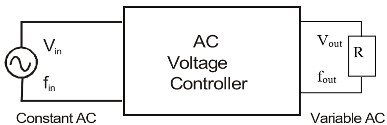
Figure 5. Schematic of AC-AC Converter at constant input and variable output
| 
|
(a) | (b) |
Figure 6. Sample of circuits for AC-AC converter (a) 1- phase AC-AC converter, (b) 3- phase AC-AC converter
Inverter
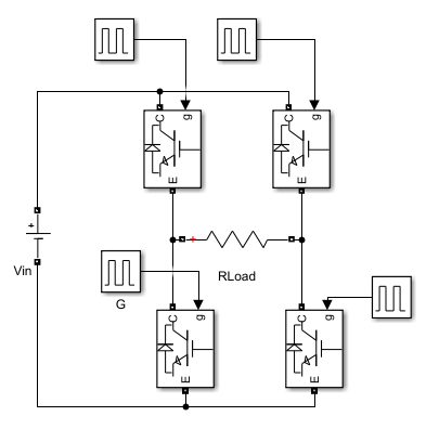
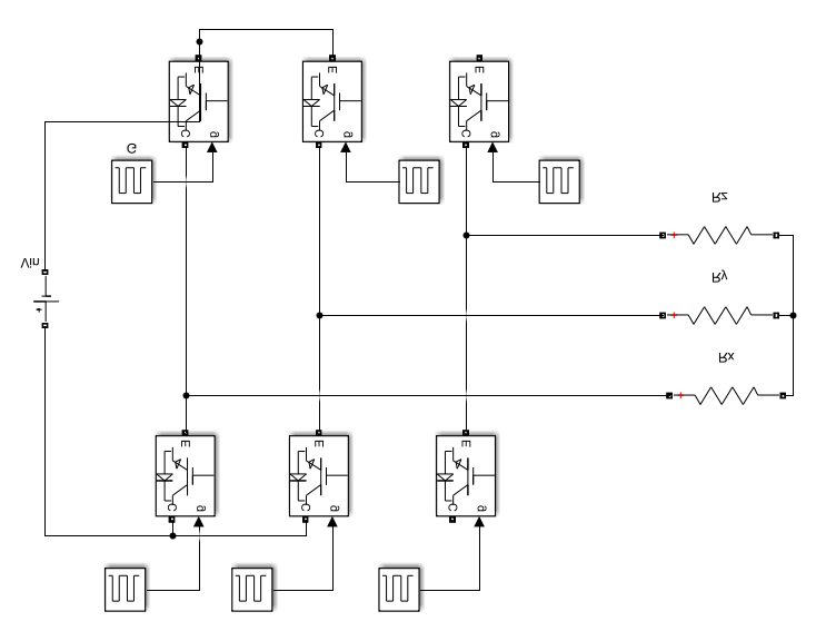
DC-AC converter (Inverter), the voltage inverter has an input from a DC source that connects to the inverter's input terminal. A solar power source, batteries, or a DC generator, which may be connected to a wind turbine, is connected to the inverter's input terminal. The inverter is designed and built with a number of electronic switches depending on the inverter type. Some of these switches are four-way switches, while the other two-way switches are single-phase (Figure 7(a)) inverters. There is another three-phase (Figure 7(b)) type consisting of three or six switches. The first type is a half-bridge type, while the second is a full-bridge type. The inverter output can be fixed voltage and frequency or variable. To control the source voltage inverter, you can use voltage control or frequency control, and you can also take the voltage-to-frequency ratio as a reference value for control. Inverter technology is the name given to modern devices that operate on the inverter principle. Modern technologies rely on relays and timers, which operate under specific conditions and shut down when those conditions change. These include refrigerators and air conditioners. To conserve as much energy as possible by consuming less and operating electrical appliances less, we connect sensors that sense operating conditions such as the temperature in room air conditioners and the cold in refrigerators, which makes them operate for a shorter period instead of continuously operating them, thus saving some energy [71]-[75].
Table 1 shows the characteristic and applications for power electronic converter. Table 2 shows the Comparison among types for power electronics converter. Table 3 shows the most important categories into which AC-to-AC power converters can be classified. This review of previous studies, which are used as scientific references for writing and presenting subcategories, includes hybrid electromagnetic converters, some of which require energy storage, others that do not, and converters that incorporate both current and voltage with pulse width modulation (PWM) technologies.
| 
|
(a) | (b) |
Figure 7. Sample of circuits for DC-AC converter (a) 1- phase DC-AC converter, (b) 3- phase DC-AC converter
Table 1. Characteristic and applications for power electronic converter
Ref. | Applications | Type of Converter | Technique | Targeted |
[1] | a grid-connected renewable source | The AC/DC and DC/DC power converters | An efficient power management technique | The method is targeted at efficient operation of distribution networks. |
[2] | renewable energy, AC Loads | One-Phase Inverter | EGS002 with SPWM | supply AC voltage to the AC load such as 8W LED lamp, 25W fan, 40W electric solder,60W incandescent lamp, and 135W electric drill. |
[3] | Renewable energy, Smart grids, | DC/DC converter DC/AC converter AC/AC converter AC/DC converter | Energy management | Electric vehicles (EVs) |
[4] | renewable energy sources | power electronic (inverter) | Optimal PSO, Fuzzy &PI Controller | different control systems with PMSM |
Table 2. Comparison among types for power electronics converter
Applications | Type of Converter | Characteristic | Input | Output |
battery chargers, Power supplies, renewable energy | Rectifier | Alternating Current to Direct Current (Converts AC to DC) | Fixed AC Input | Variable DC Output |
AC Loads, renewable energy, Smart grids, | Inverter | Direct Current to Alternating Current (Converts DC to AC) | Fixed DC Input | Variable AC Output |
Renewable energy, Smart grids, | AC Voltage controller | Direct Current to Direct Current(Converts AC to AC) | Fixed AC Input | Variable AC Output |
Electric vehicles, energy storage, | DC Choppers | Alternating Current to Alternating Current (Converts AC to AC) | Fixed DC Input | Variable DC Output |
Table 3. technical literature of ac–ac converter topologies [88]-[116]
References | Converter | Technical Literature | Converter Topologies |
[88] | Power electronic converter (AC-AC) | Converter with DC Link storage | Converter with Voltage DC Link storage(V-BBC)(VR-VSI) |
[89][90] | Power electronic converter (AC-AC) | Converter with DC -Link storage | Converter with Voltage-Current DC -Link storage(ZSC, TSC) |
[91]-[93] | Power electronic converter (AC-AC) | Converter with DC Link storage | Converter with Current DC -Link storage(C-BBC) |
[94][95] | Power electronic converter (AC-AC) | Hybrid Matrix converter | Hybrid Direct Matrix converter (HCMC) |
[96] | Power electronic converter (AC-AC) | Hybrid Matrix converter | Hybrid Indirect Matrix converter (HCMC) |
[97]-[99] | Power electronic converter (AC-AC) | Matrix Converter | Direct Matrix converter-conventional (CMC)(SAX) |
[100]-[102] | Power electronic converter (AC-AC) | Matrix Converter | Direct Matrix converter –Full Bridge (open Motor winding) |
[103]-[105] | Power electronic converter (AC-AC) | Matrix Converter | Indirect Matrix converter (18-switches)(IMC) |
[106]-[108] | Power electronic converter (AC-AC) | Matrix Converter | three level- Indirect Matrix converter |
[109]-[111] | Power electronic converter (AC-AC) | Matrix Converter | Sparse-Indirect Matrix converter (SMC,VSMC,USMC) |
[112]-[114] | Power electronic converter (AC-AC) | Matrix Converter | Indirect Matrix converter without DC-Link capacitor(F3EC) |
[115][116] | Power electronic converter (AC-AC) | Matrix Converter | Buck converter(AC chopper) |
POWER ELECTRONIC CONVERTERS FOR MOTOR DRIVES
Motors operate after being fed with electrical current. The first type operates after being fed with direct electrical current, and the second type operates after being fed with alternating electrical current. It includes single-phase and three-phase motors. Motors are similar in that they are composed of two parts, fixed and moving. They differ in the number of coil turns of the fixed part, and they differ in the size of the wire diameter of the coils and the method of connection according to the power of the motor and the number of poles to suit the required horsepower and the speed at which it rotates. The motor is considered a converter of electrical energy into mechanical energy, and the amount of mechanical output power depends on the design. The electrical input power therefore depends on the composition of the motor, the type of coils, and the method of connecting them. The basis for the operation of an electric motor is to supply it with voltage from an electrical power source, after which an electric current flows through the motor coils in a closed path, generating the magnetic flux in the air gap between the rotor and the stator, and from it a magnetic motive force is generated. It moves the rotor at a speed that depends on the amount of driving force, which in turn depends on the amount of flux generated, which depends on the amount of electric current, and the electric current depends on the amount of resistance of the coils, which depends on the thickness of the wire and the number of turns of the stator coils [76]-[80]. Figure 8 represents a voltage inverter connected to a load on the output side and a power source on the input side. The figure also shows the types of switches that can be used to construct an inverter, as well as some types of loads and some types of power sources for the inverter's input terminal.
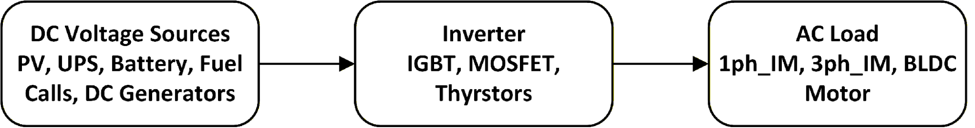
Figure 8. Schematic of a source voltage inverter system.
A voltage inverter converts direct current (DC) to alternating current (AC). The inverter's input is connected to a DC source, while its output is connected to an AC load. The inverter's output may be connected to the grid or to another type of transformer, depending on the application. An important application for inverters is operating induction motors, such as in electric vehicle drive systems. They can be classified as single-phase voltage inverters and three-phase voltage inverters. Other types include half-bridge voltage inverters and full-bridge voltage inverters. Some studies on inverters may be similar, but differ, in terms of the number and type of electronic switches, the switching frequency of these switches, the type of filter associated with the inverter output, the inverter's input power source, other control systems, storage units, operating period, suitable applications, fault types, and many other topics related to voltage inverter systems, such as power supply systems for conventional fuel-powered systems such as AC generators and DC generators, power generation plants, and renewable energy systems [81]-[85]. The source voltage inverter can be represented by a diagram showing the system components, power supply terminals, and load, as shown in Figure 9(a) Another diagram showing the inverter components according to type and classification is shown in Figure 9(b), Figure 9(c) and Figure 9(d).
The system that drives the engine can be dampened by the fuel source, a control unit, an electronic power converter, sensors, and the electric motor. The control board relies on a reference signal that is compared with the actual output signal, and the comparison output must be as small as possible, and in the ideal case it will be zero, meaning the system works without error. When it works the system is in a stable state. Operating conditions can change and it turns into an unstable system state. Here comes the role of control systems to return the system to a stable state. It is called a change state. It is a transient state when the system departs from a stable state and returns to it [86]-[90]. Electronic power converters are used in a wide range of applications that require mechanical power to be driven by an electric motor. Electronic power converters depend on the process of electronic switching using electronic switches, and to provide appropriate behavior for the conversion process, we need to know the most important strategies adopted to achieve the highest efficiency in the conversion process [91]-[95].
In general, when choosing which system to drive the motor, you must focus on designing a system capable of producing an appropriate mechanical force that represents the force required at the output of the electric motor. To achieve the required power at the motor output, we need to provide the appropriate electrical power for this, and therefore we need a frequency and voltage to achieve this. The transformer works to provide the required and appropriate voltage and frequency at the output side of the transformer, while the source power with a certain frequency and voltage is linked to the transformer input, which can be used and converted according to the design of the electronic power transformer. The output of the electric motor is a mechanical force represented by the torque of the motor, as well as the speed of rotation of the rotor of the motor, which can be controlled in addition to the position of the rotor through the control systems associated with the system. It can be controlled by providing an appropriate output to the transformer that represents an input terminal to the motor. The control systems are connected to sensors for the engine output that is to be controlled using feedback with an appropriate control unit to handle errors in the system, such as transient states and system instability, and return it to a stable state as quickly as possible, eliminating system errors [96]-[100].
Figure 9. Block diagram system of Inverter (a) Block diagram general system of Inverter, (b) Block diagram single phase system of Inverter, (c) Block diagram 1ph_IM system of Inverter, (d) Block diagram 3ph_IM system of Inverter
SIMULATION MODEL OF POWER ELECTRONIC CONVERTER
A simulation model can be designed and built using a diode-type electronic switch, as well as a model without other control (Figure 10 to Figure 17). Control can be done using a transistor or thyristor. It also requires determining the available input value, which provides a load capacity, from which the load's electrical quantities (current, voltage, and resistance) can be determined. The model can also be simulated to verify its effectiveness and the feasibility of using electronic switches to manage the converter's operation and provide the required output voltage to cover the required load [101]-[105].
This section includes four parts, the first part an AC-AC converter identifies a type of electronic converter, which is an alternating current converter to alternating current. It is classified into single-phase and three-phase converters. The second part a DC-AC converter identifies a type of electronic converter, which is a direct current converter to alternating current. It is classified into single-phase and three-phase inverters. The third part an AC-AC converter identifies a type of electronic converter, which is an alternating current converter to direct current. It is classified into single-phase and three-phase rectifiers. The fourth part a DC-AC converter identifies a type of electronic converter, which is a direct current converter to direct current. It is classified into step-up converter and step-down converter [106]-[110].
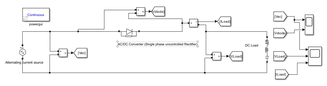
Figure 10. Simulation model of 1ph- Half wave uncontrolled for AC/DC power electronic converter
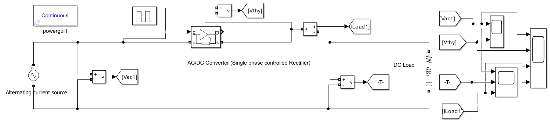
Figure 11. Simulation model of 1ph- Half wave controlled for AC/DC power electronic converter
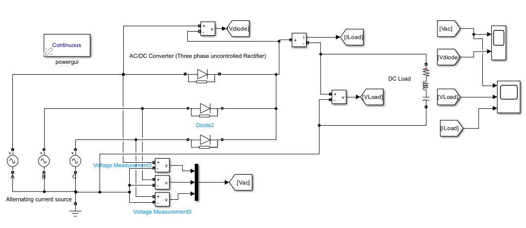
Figure 12. Simulation model of 3ph- Half wave uncontrolled for AC/DC power electronic converter
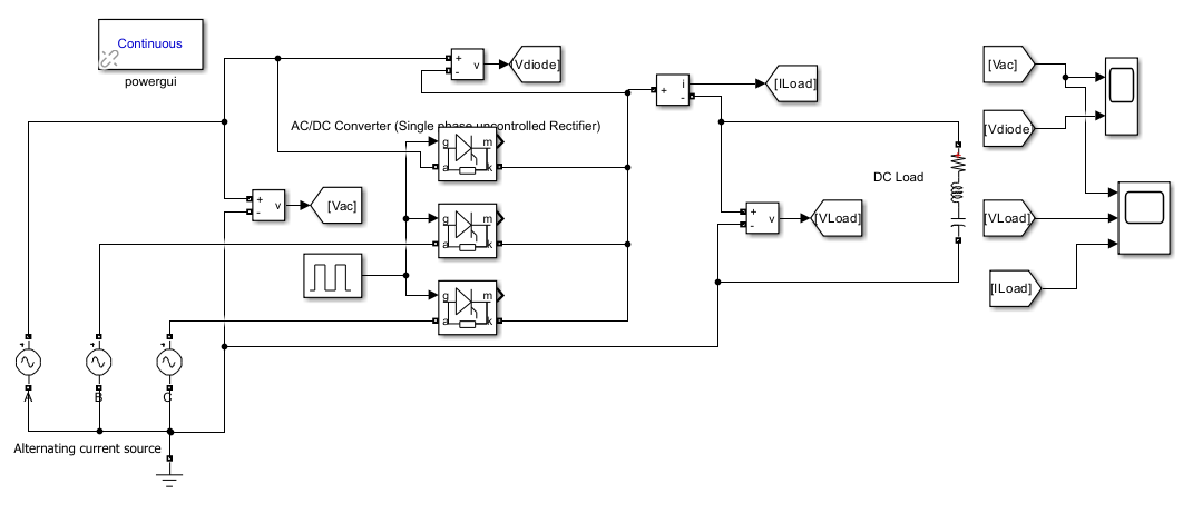
Figure 13. Simulation model of 3ph- Half wave controlled for AC/DC power electronic converter
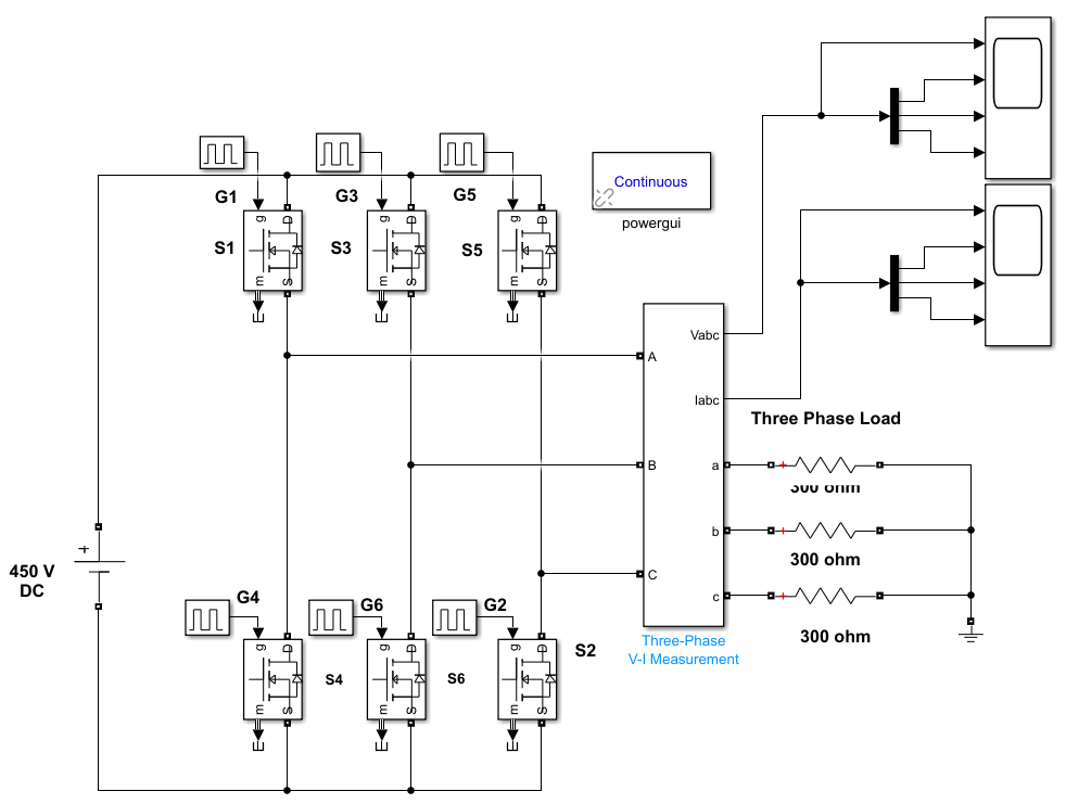
Figure 14. Simulation model of 3ph-Full wave controlled for DC/AC power electronic converter
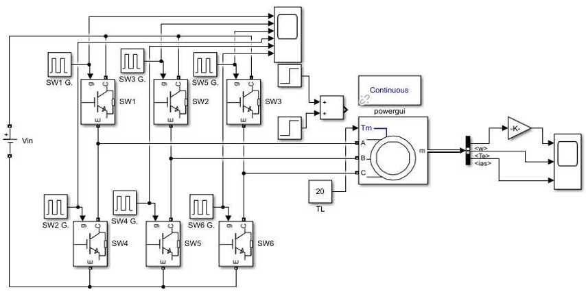
Figure 15. Simulation model of 3ph-Full wave controlled for 3-ph IM
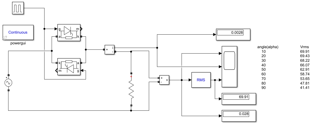
Figure 16. Simulation Model for 1-ph AC-AC Converter
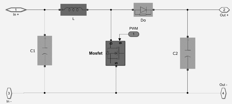
Figure 17. Simulation Model for DC-DC Converter
CONCLUSIONS
In this review, a study of electronic power converters was presented and proposed. The review identified and examined the types of electronic power converters and their functions, allowing the appropriate application to be determined based on their functions. A modeling and simulation study was conducted, and simulation models of some of the proposed converters were tested to understand their behavior and operating characteristics using MATLAB. Finally, it is recommended that electronic power converters be used as an essential component in many fields that require converting the type or magnitude of an electrical quantity at different levels, depending on the need.
The importance of studying power electronics stems from its widespread use and applications in various fields, including industry, which is a major component of everyday life for all countries around the world.
- Development and progress in various fields of technology have encompassed power electronics with all its components, including devices, circuits, and transformers, enhancing the efficiency of these systems and making them a focus of specialists.
- It has developed solutions to all problems that have been identified over time, both in the past and present, and will continue to be addressed in the future and in the future of advanced science.
- There are numerous applications, including the presence of power electronics systems in stations, transportation, and renewable energy, as well as in vehicles, communications, and other fields.
- Most systems require controlling the required and appropriate amounts of power to operate with a specific behavior that overcomes any potential disturbances during immediate operation.
- Power electronics is one of the most important units assisting in the power control process, as it is linked to various control units to provide the appropriate type and quantity of power to meet the demand for system loads.
Power electronics includes DC-DC converters, which provide a constant DC voltage. The load is a DC motor whose speed changes when running, requiring a change in the applied voltage. This requires an electronic power converter.
- Converting a constant-value AC input to a variable-value AC output depending on the application. One such application is providing an AC voltage. The load is an AC motor whose speed changes when running, requiring a change in the applied voltage. This requires an electronic power converter.
- Changing the type of current and electrical quantities: converting a constant-value AC current to a constant or variable DC current, depending on the application and desired scope of use. This is called a rectifier. Finally, an inverter, which operates in reverse, consists of a constant-value DC input and a constant or variable AC output, depending on the application and desired scope of use.
- A study can be developed that includes system components for one of these units, along with a simulation model and system operation under various operating conditions.
REFERENCES
- O. Olatunde, U. F. Okoro, and A. T. Tola, “Multiagent based Power Management for Grid-connected Photovoltaic Source Using the Optimized Network Parameters From Butterworth Inertia Weight Particle Swarm Optimization,” Buletin Ilmiah Sarjana Teknik Elektro, vol. 6, no. 4, pp. 366-380, 2024, https://doi.org/10.12928/biste.v6i4.11391.
- N. S. A. Kaliky, S. A. Akbar, and A. R. C. Baswara, “Design of One-Phase Inverter Using EGS002 with SPWM,” Buletin Ilmiah Sarjana Teknik Elektro, vol. 4, no. 3, pp. 132-141, 2023, https://doi.org/10.12928/biste.v4i3.6567.
- M. I. Habib, “Review of Power Electronics for Smart Sustainable Energy Systems,” ASEAN Journal on Science and Technology for Development, vol. 43, no. 1, p. 1, 2026, https://doi.org/10.61931/2224-9028.1631.
- H. Gong et al., “A megawatt ultra-wide bandgap semiconductor module for pulsed power electronics,” Nature Communications, 2026, https://doi.org/10.1038/s41467-026-71274-6.
- A. N. Widyanto, M. A. K. Adhi, F. Husnayain, A. R. Utomo, and I. M. Ardita, “Techno–Economic Analysis of Rooftop Solar Panel Uprating on Commercial Building (Casestudy on Karawang Branch Office of XYZ Company),” Buletin Ilmiah Sarjana Teknik Elektro, vol. 5, no. 1, pp. 86-97, 2023, https://doi.org/10.12928/biste.v5i1.7579.
- O. Olatunde, U. F. Okoro, and A. T. Tola, “Multiagent based Power Management for Grid-connected Photovoltaic Source Using the Optimized Network Parameters From Butterworth Inertia Weight Particle Swarm Optimization,” Buletin Ilmiah Sarjana Teknik Elektro, vol. 6, no. 4, pp. 366-380, 2024, https://doi.org/10.12928/biste.v6i4.11391.
- C. Wyon and M. V. de Voorde, "New Challenges for the Semiconductor Ecosystem," in IEEE Electron Devices Reviews, vol. 2, pp. 330-360, 2025, https://doi.org/10.1109/EDR.2025.3638339.
- A. Dasgupta, S. Sen, P. Singh, and A. Raman, “A Comprehensive Overview of the Foundations of Semiconductor Materials,” Semiconductor Nanoscale Devices: Materials and Design Challenges, pp. 80-109, 2025, https://doi.org/10.2174/9789815313208125010007.
- U. Soma, “Transistor Evolution: A Comprehensive Overview from TFT to TFET and Beyond: U. Soma,” Proceedings of the National Academy of Sciences, India Section A: Physical Sciences, vol. 95, no. 2, pp. 113-125, 2025, https://doi.org/10.1007/s40010-025-00915-0.
- R. Khale, R. Sangale, S. K. Agrawal and D. Pardeshi, "Design and Realization of a Multi-Level DC-AC Converter for High-Efficiency Power Conversion," 2025 3rd International Conference on Inventive Computing and Informatics (ICICI), pp. 1535-1541, 2025, https://doi.org/10.1109/ICICI65870.2025.11069951.
- Y. Oren et al., “Modeling and experimental validation of broad input-output range three-voltage-level rectifier,” Inventions, vol. 9, no. 2, p. 37, 2024, https://doi.org/10.3390/inventions9020037.
- H. M. Usman et al., “Optimization of grid-connected PV systems: Balancing economics and environmental sustainability in Nigeria,” Buletin Ilmiah Sarjana Teknik Elektro, vol. 6, no. 3, pp. 237-253, 2024, https://doi.org/10.12928/biste.v6i3.11562.
- X. Wang and X. Li, "A Review on the Utilization of Regenerative Braking Energy in Maglev Train Traction Power," 2025 IEEE China International Youth Conference on Electrical Engineering (CIYCEE), pp. 1-6, 2025, https://doi.org/10.1109/CIYCEE67631.2025.11308742.
- F. Battal, D. Boss, R. H. Poelma, E. Vlieg, and J. J. Schermer, “Advancements in TLP Bonding for Power Electronics Die‐Attach Applications,” Advanced Materials Technologies, vol. 11, no. 4, p. e01166, 2026, https://doi.org/10.1002/admt.202501166.
- K. Namrata, R. P. Saini, and D. P. Kothari, “Grid Integration Techniques in Solar and Wind-Based Energy Systems,” In Wind and Solar Energy Systems, pp. 273-339, 2024, https://doi.org/10.1007/978-981-99-9710-7_6.
- T. Sutikno, M. S. Pradana, and A, Pamungkas, “One-Shot Pulse Boost Converter-Based Inductor-Synchronized Piezoelectric Energy Harvester,” Buletin Ilmiah Sarjana Teknik Elektro, vol. 6, no. 2, pp. 104-112, 2024, https://doi.org/10.12928/biste.v6i2.10020.
- T. Abuzairi and R. W. Rachmad, “Simple Simulation of Perturb and Observe MPPT Algorithm on Synchronous Buck Converte,” Buletin Ilmiah Sarjana Teknik Elektro, vol. 5, no. 4, pp. 448-454, 2023, https://doi.org/10.12928/biste.v5i4.9347.
- A. Sakhare and S. Mikkili, “Advanced DC–DC converter topologies for electric vehicles: Wide bandgap technologies, emerging trends and future challenges,” Electrical Materials and Applications, vol. 2, no. 1, p. e70023, 2025, https://doi.org/10.1049/ema3.70023.
- K. A. Nugraha and T. Sutikno, “PID Control Based DC Boost Converter on Wheeled Soccer Robot,” Buletin Ilmiah Sarjana Teknik Elektro, vol. 3, no. 2, p. 106-114, 2021, https://doi.org/10.12928/biste.v3i2.3942.
- S. Kumari, S. S. Sahu, and B. Gupta, “Efficient SSHI circuit for piezoelectric energy harvester uses one shot pulse boost converter,” Analog Integrated Circuits and Signal Processing, vol. 97, no. 3, pp. 545-555, 2018, https://doi.org/10.1007/s10470-018-1218-1.
- K. Salitha, H. A. Vidya and J. Ramprabhakar, "Advancement of Power Electronic Converter and Control Methods in Microgrid Systems: A Review," in IEEE Access, vol. 14, pp. 4402-4434, 2026, https://doi.org/10.1109/ACCESS.2025.3650614.
- R. W. Rachmad and T. Abuzairi, “Efficiency Comparison of Asynchronous and Synchronous Buck Converter with Variation in Duty Cycle and Output Current,” Buletin Ilmiah Sarjana Teknik Elektro, vol. 5, no. 1, pp. 41-55, 2023, https://doi.org/10.12928/biste.v5i1.7386.
- S. Coelho, V. Monteiro, and J. L. Afonso, “Topological advances in isolated DC–DC converters: high-efficiency design for renewable energy integration,” Sustainability, vol. 17, no. 6, p. 2336, 2025, https://doi.org/10.3390/su17062336.
- Y. Huo et al., “Emerging Advanced Electronic Packaging Materials for Thermal Management in Power Electronics,” Advanced Science, vol. 13, no. 17, p. e24348, 2026, https://doi.org/10.1002/advs.202524348.
- R. Stewart and S. Jack, “High Step-Up DC-DC Converter Soft Computing Module for PV Module,” Journal of Science Engineering Technology and Management Science, vol. 2, no. 05, 2025, https://doi.org/10.63590/jsetms.2025.v02.i05.pp26-31.
- A. M. Muslu and Y. Joshi, “Unlocking the Potential of Integrated Cooling and Power Delivery in Multi-chip Power Electronics Packages with Triply Periodic Minimal Surfaces (TPMS),” International Journal of Heat and Mass Transfer, vol. 255, p. 127866, 2026, https://doi.org/10.1016/j.ijheatmasstransfer.2025.127866.
- M. Motamedi-Sedeh, S. A. M. Lahaghi, A. Abbasi-Moghaddam, B. Zaker and E. Farjah, "A New Topology of the High Step-Up Z-Source Three-Level DC-DC Converter," 2025 16th Power Electronics, Drive Systems, and Technologies Conference (PEDSTC), pp. 1-7, 2025, https://doi.org/10.1109/PEDSTC65486.2025.10912014.
- A. Nadermohammadi, M. M. Hayati, A. Oshnoei, S. H. Hosseini, E. Babaei and M. Abapour, "Ultra-High Step-Up Quadratic DC-DC Converter with Soft Switching, High Efficiency, and Cost Effectiveness for DC Microgrid Applications," 2025 16th Power Electronics, Drive Systems, and Technologies Conference (PEDSTC), pp. 1-7, 2025, https://doi.org/10.1109/PEDSTC65486.2025.10911981.
- N. Soni, A. C. Umarikar and A. S. Vijay, "Control Aspects of Multifunctional Converters in AC Microgrids: A Survey," in IEEE Access, vol. 13, pp. 91889-91901, 2025, https://doi.org/10.1109/ACCESS.2025.3573154.
- Y. Tong, I. Salhi, Q. Wang, G. Lu, and S. Wu, “Bidirectional DC-DC converter topologies for hybrid energy storage systems in electric vehicles: a comprehensive review,” Energies, vol. 18, no. 9, p.2312, 2025, https://doi.org/10.3390/en18092312.
- I. Soltani, G. R. Molaeimanesh, H. Gholizadeh and H. Vahedi, "A Review of High-Step-Up Non-Isolated DC–DC Converters Focusing on the Topology Methodology and Features," in IEEE Access, vol. 14, pp. 54320-54352, 2026, https://doi.org/10.1109/ACCESS.2026.3681231.
- M. P. Kazmierkowski, "Power Electronics in Renewable Energy Systems and Smart Grid: Technology and Applications [Book Review]," in IEEE Power Electronics Magazine, vol. 7, no. 2, pp. 94-94, June 2020, https://doi.org/10.1109/MPEL.2020.2987668.
- T. Sakthiram, L. Yogesh, R. Srikanth, M. Prabhakar, and S. Angalaeswari, “Single-switch ultra-high step-Up DC-DC converter for PV applications,” Results in Engineering, vol. 25, p. 104050, 2025, https://doi.org/10.1016/j.rineng.2025.104050.
- U. E. Boniface, “Power electronics and drives engineering advancing electrification automation efficiency electric mobility industrial energy conversion systems applications globally scalable,” Global Journal of Engineering and Technology Advances, vol. 26, no. 01, pp. 050-068, 2026, https://doi.org/10.30574/gjeta.2026.26.1.0007.
- T. Sakthiram, L. Yogesh, R. Srikanth, M. Prabhakar, and K. Varesi, “Interleaved quartic high gain DC–DC converter,” Scientific Reports, vol. 15, no. 1, p. 216, 2025, https://doi.org/10.1038/s41598-024-84015-w.
- M. Alharbi, “The dual role of grid-forming inverters: power electronics innovations and power system stability,” Electronics, vol. 15, no. 5, p. 1115, 2026, https://doi.org/10.3390/electronics15051115.
- P. Szczesniak, “Challenges and design requirements for industrial applications of AC/AC power converters without DC-link,” Energies, vol. 12, no. 8, p. 1581, 2019, https://doi.org/10.3390/en12081581.
- G. Anusha, A. V. V. Sudhakar, R. R. R. Deshmukh, and C. H. Basha, “A bibliometric analysis of research trends in electric vehicle power electronics: global perspectives and future directions,” Discover Applied Sciences, vol. 7, no. 5, p. 487, 2025, https://doi.org/10.1007/s42452-025-06996-1.
- M. A. Tawfik, M. Ehab, A. Ahmed and J. -H. Park, "Single-Stage Isolated AC/AC Converter With Phase-Shifted Controller," in IEEE Journal of Emerging and Selected Topics in Power Electronics, vol. 11, no. 2, pp. 1815-1826, 2023, https://doi.org/10.1109/JESTPE.2022.3219023.
- S. K. Mazumder, J. H. Enslin and F. Blaabjerg, "Guest Editorial: Special Issue on Sustainable Energy Through Power-Electronic Innovations in Cyber-Physical Systems," in IEEE Journal of Emerging and Selected Topics in Power Electronics, vol. 9, no. 5, pp. 5142-5145, 2021, https://doi.org/10.1109/JESTPE.2021.3109578.
- K. V. Reshma, “Enhanced Efficiency of DC-AC Grid-Tied Converters for Photovoltaic Systems using AC-Link Integration,” CVR Journal of Science and Technology, vol. 27, no. 1, pp. 60-66, 2025, https://cvr.ac.in/ojs/index.php/cvracin/article/view/945.
- M. E. Sulistyo, D. D. Susilo, M. Nizam, and U. Ubaidillah, “A literature review: bearing fault in bldc motor based on vibration and thermal signals,” Journal of Electrical, Electronic, Information, and Communication Technology, vol. 7, no. 1, pp. 10-15, 2025, https://doi.org/10.20961/jeeict.7.1.100165.
- A. R. Al Tahtawi, S. Yahya, P. Elbizzar, and S. M. Ilman, “Speed Control of 3 Phase 1.5 kW Induction Motor using VSD LS SV015IG5A-2 with Proportional Integral Anti-Windup Method,” Journal of Fuzzy Systems and Control, vol. 2, no. 3, pp. 140-146, 2024, https://doi.org/10.59247/jfsc.v2i3.242.
- H. Maghfiroh, A. J. Titus, A. Sujono, F. Adriyanto, and J. S. Saputro, “Induction motor torque measurement using prony brake system and close-loop speed control,” International Journal of Robotics and Control Systems, vol. 2, no. 3, pp. 594-605, 2022 https://doi.org/10.31763/ijrcs.v2i3.782.
- H. Maghfiroh, I. Iftadi, and A. Sujono, “Speed Control of Induction Motor using LQG,” Journal of Robotics and Control (JRC), vol. 2, no. 6, pp. 565-570, 2021, https://doi.org/10.18196/26138.
- M. Swargiary, J. Dey, and T. K. Saha, “Optimal Speed Control of Induction Motor Based on Linear Quadratic Regulator Theory,” Annual IEEE India Conference (INDICON), 2015, https://doi.org/10.1109/INDICON.2015.7443806.
- M. Magzoub, N. Saad, R. Ibrahim, and M. Irfan, “An experimental demonstration of hybrid fuzzy-fuzzy space- vector control on AC variable speed drives,” Neural Computing and Applications, pp. 1-16, 2017, https://doi.org/10.1007/s00521-017-3008-6.
- B. R. Ke, H. Maghfiroh, K. L. Lian, N. Chen, and D. F. Teshome, “Model of traction system and speed control for single train of Taipei mass rapid transit system,” IEEE International Conference on Advanced Intelligent Mechatronics (AIM), pp. 781-787, 2016, https://doi.org/10.1109/AIM.2016.7576863.
- M. M. Islam, S. A. Siffat, I. Ahmad, and M. Liaquat, “Adaptive Nonlinear Control of Unified Model of Fuel Cell, Battery, Ultracapacitor and Induction Motor Based Hybrid Electric Vehicles,” IEEE Access, vol. 9, pp. 57486-57509, 2021, https://doi.org/10.1109/ACCESS.2021.3072478.
- F. Battal, D. Boss, R. H. Poelma, E. Vlieg, and J. J. Schermer, “Advancements in TLP Bonding for Power Electronics Die‐Attach Applications,” Advanced Materials Technologies, vol. 11, no. 4, p. e01166, 2026, https://doi.org/10.1002/admt.202501166.
- F. Y. Notash, J. He and H. Li, "Towards Digital Twin Driven High-Reliability Power Electronic Converters," in IEEE Open Journal of Power Electronics, vol. 7, pp. 683-721, 2026, https://doi.org/10.1109/OJPEL.2026.3664414.
- L. Tightiz and W. K. Al-Shibli, “Novel AC–AC Converter Design for High‐Efficiency Wireless Electric Vehicle Charging Systems,” International Journal of Energy Research, vol. 2025, no. 1, p. 8866716, 2025, https://doi.org/10.1155/er/8866716.
- K. P. Uvarajan, “Intelligent Control of Power Electronic Converters for Renewable Energy Grid Integration,” National Journal of Intelligent Power Systems and Technology, pp. 1-8, 2026, https://www.secitsociety.org/index.php/NJIPST/article/view/318.
- S. P. Biswas, M. S. Uddin, M. R. Islam, S. Mondal, and J. Nath, “A Direct Single-Phase to Three-Phase AC/AC Power Converter,” Electronics, vol. 11, no. 24, p. 4213, 2022, https://doi.org/10.3390/electronics11244213.
- H. Baik and J. Roy, "Review of Power Electronic Solutions for Dielectric Barrier Discharge Applications," in IEEE Transactions on Power Electronics, vol. 41, no. 7, pp. 11585-11610, 2026, https://doi.org/10.1109/TPEL.2026.3658517.
- H. Wang, S. Xie, and L. Yuan, “A Single-Phase AC-AC Power Electronic Transformer Without Bulky Energy Storage Elements,” Energies, vol. 18, no. 7, p. 1769, 2025, https://doi.org/10.3390/en18071769.
- N. K. Krishnamurthy, A. K. Pandey, S. Birla, G. Manikanta, and S. Kumar, “Smart inverters based technological advancements in future smart grids for improved flexible renewable energy penetration,” Discover Energy, vol. 5, no. 1, p. 28, 2025, https://doi.org/10.1007/s43937-025-00087-3.
- M. A. Barrios, V. Cárdenas, J. M. Sandoval, J. M. Guerrero, and J. C. Vasquez, “A cascaded DC-AC-AC grid-tied converter for PV plants with AC-link,” Electronics, vol. 10, no. 4, p. 409, 2021, https://doi.org/10.3390/electronics10040409.
- A. Udabe, I. Baraia-Etxaburu and D. G. Diez, "Gallium Nitride Power Devices: A State of the Art Review," in IEEE Access, vol. 11, pp. 48628-48650, 2023, https://doi.org/10.1109/ACCESS.2023.3277200.
- V. Jagan, G. Sainath, M. Navyasri, A. Shiva, K. Chenchireddy and P. Giri, "Investigations on Novel Extreme-Boost DC-AC Converter," 2025 International Conference on Next Generation Communication & Information Processing (INCIP), pp. 875-880, 2025, https://doi.org/10.1109/INCIP64058.2025.11019806.
- K. Suresh, E. Parimalasundar, and P. Aravind, “A high-efficiency multi-port bidirectional converter for renewable energy and hybrid electric vehicle applications,” Scientific Reports, 2026, https://doi.org/10.1038/s41598-026-48981-7.
- Y. Du, X. Lu, and X. Wang, “Power system operation with power electronic inverter–dominated microgrids,” In New Technologies for Power System Operation and Analysis, pp. 259-274, 2021, https://doi.org/10.1016/B978-0-12-820168-8.00008-0.
- A. Lahooti Eshkevari, I. Abdoli, M. Karimi Hajiabadi, and A. Mosallanejad, “High step‐up direct ac‐ac boost converter with optimal component counts based on SEPIC,” IET Power Electronics, vol. 17, no. 9, pp. 1106-1118, 2024, https://doi.org/10.1049/pel2.12644.
- J. He, P. Mattavelli and F. Briz, "Guest Editorial Special Issue on Digital Twin Driven High-Reliability Power Electronic Systems," in IEEE Journal of Emerging and Selected Topics in Power Electronics, vol. 13, no. 3, pp. 2709-2711, 2025, https://doi.org/10.1109/JESTPE.2025.3575229.
- D. S. Osheba, S. M. Ahmed, and A. E. Lashine, “Analysis and experimental validation of single-phase cascaded boost AC–AC converter with high voltage gain,” Sustainability, vol. 15, no. 4, p. 3353, 2023, https://doi.org/10.3390/su15043353.
- K. Tehrani et al., "A Survey of AI in System of Systems With a Focus on Power Electronic Systems—Part II: Maintenance and Forecasting," in IEEE Systems Journal, vol. 19, no. 4, pp. 1025-1037, 2025, https://doi.org/10.1109/JSYST.2025.3641439.
- Z. Xiong and L. He, "A Single Phase Frequency-Variable Cuk-Type AC-AC Converter With Natural Commutation and Continuous Current," in IEEE Access, vol. 13, pp. 32357-32370, 2025, https://doi.org/10.1109/ACCESS.2025.3543024.
- P. Manoharan and B. Chandrasekar, “Compact Single-Stage Optimized Power Electronic Converter for Dual-Mode Wired and Wireless Technologies for Versatile EV Charging Infrastructure,” Results in Engineering, p. 110535, 2026, https://doi.org/10.1016/j.rineng.2026.110535.
- A. Kumar, R. Chaki and A. Dey, "Design of a Wind Emulator for Grid-Connected Type-IV Wind Energy Conversion Systems," 2025 IEEE International Conference on Power Electronics, Smart Grid, and Renewable Energy (PESGRE), pp. 1-6, 2025, https://doi.org/10.1109/PESGRE65581.2025.11521819.
- Ye, J., Xuan, W., Guo, Q., Liu, Y., Wang, B., Zhang, X., & Iu, H. H. C. (2026). An overview of reinforcement learning for power electronic converters: Topology derivation, parameter design, and control implementation. Renewable and Sustainable Energy Reviews, 228, 116591, 2026, https://doi.org/10.1016/j.rser.2025.116591.
- L. Gumilar, I. Ridzki, A. Muazib, A. I. Syah, and M. Z. Falah, “Dynamic Voltage Restorer for Mitigation of Voltage Sags Due to 3 Phase Motor Starts Based on Artificial Neural Networks,” J. Ilm. Tek. Elektro Komput. and Inform., vol. 9, no. 1, pp. 200–211, 2023, https://doi.org/10.26555/jiteki.v9i1.25897.
- H. Maghfiroh, M. R. Subeno, M. R. Darmawan, and R. Prihananto, “A survey on traction motor and its prototyping method for electric vehicle application,” J. Electr. Electron. Inf. Commun. Technol., vol. 5, no. 1, pp. 21–26, 2023, https://doi.org/10.20961/jeeict.5.1.71317.
- M. Y. A. Khan, “Enhancing electric vehicle performance: A case study on advanced motor drive systems, integration, efficiency, and thermal management,” Control Syst. Optim. Lett., vol. 3, no. 1, pp. 20–27, 2025, https://doi.org/10.59247/csol.v3i1.152.
- H. Maghfiroh and C. Hermanu, “Optimal energy control of railway traction motor: Comparative study,” in AIP Conf. Proc., vol. 2097, no. 1, 2019, https://doi.org/10.1063/1.5098195.
- L. Guangqiang, H. Fei, L. Qiang and J. Yanchao, "Torque close-loop control of a novel soft starter of induction motor," 2013 IEEE International Symposium on Industrial Electronics, pp. 1-6, 2013, https://doi.org/10.1109/ISIE.2013.6563613.
- U. Sengamalai, G. Anbazhagan, T. M. Thamizh Thentral, P. Vishnuram, T. Khurshaid, and S. Kamel, “Three phase induction motor drive: A systematic review on dynamic modeling, parameter estimation, and control schemes,” Energies, vol. 15, no. 21, p. 8260, 2022, https://doi.org/10.3390/en15218260.
- A. Alwadie, “A concise review of control techniques for reliable and efficient control of induction motor,” International Journal of Power Electronics and Drive Systems, vol. 9, no. 3, p. 1124, 2018, http://doi.org/10.11591/ijpeds.v9.i3.pp1124-1139.
- S. Roy and R. Pandey, "Efficiency Optimization of Vector Controlled Induction Motor Drive by Field Orientation Technique," 2023 Third International Conference on Advances in Electrical, Computing, Communication and Sustainable Technologies (ICAECT), pp. 1-5, 2023, https://doi.org/10.1109/ICAECT57570.2023.10118261.
- T. Sutikno, N. R. N. Idris, and A. Jidin, “A review of direct torque control of induction motors for sustainable reliability and energy efficient drives,” Renewable Sustainable Energy Review, vol. 32, pp. 548–58, 2014, https://doi.org/10.1016/j.rser.2014.01.040.
- Y. Zahraoui, M. Akherraz, C. Fahassa, and S. Elbadaoui, “Induction Motor DTC Performance Improvement by Reducing Flux and Torque Ripples in Low Speed,” J. Robot. Control, vol. 3, no. 1, pp. 93–100, 2022, https://doi.org/10.18196/jrc.v3i1.12550.
- V. Shekher, A. Sisodiya, A. K. Sinha, H. Harsh, and N. Soren, "Optimal tuning of PID controller for V/f control of linear induction motor using artificial biological intelligence," Franklin Open, vol. 9, p. 100183, 2024, https://doi.org/10.1016/j.fraope.2024.100183.
- H. Maghfiroh, A. Ma’arif, F. Adriyanto, I. Suwarno, and W. Caesarendra, “Adaptive Linear Quadratic Gaussian Speed Control of Induction Motor Using Fuzzy Logic,” J. Eur. des Systèmes Autom., vol. 56, no. 4, pp. 703–711, 2023, https://doi.org/10.18280/jesa.560420.
- Y. Zahraoui, M. Akherraz, and A. Ma’arif, “A Comparative Study of Nonlinear Control Schemes for Induction Motor Operation Improvement,” Int. J. Robot. Control Syst., vol. 2, no. 1, pp. 1–17, 2021, https://doi.org/10.31763/ijrcs.v2i1.521.
- M. Zhou, S. Cheng, Y. Feng, W. Xu, L. Wang, and W. Cai, “Full-order terminal sliding-mode-based sensorless control of induction motor with gain adaptation,” IEEE Journal of Emerging and Selected Topics in Power Electronics, vol. 10, no. 2, pp. 1978–1991, 2021, https://doi.org/10.1109/JESTPE.2021.3081863.
- C-K. Lin, “Radial basis function neural network-based adaptive critic control of induction motors,” Appl. Soft Computing, vol. 11, no. 3, 3066–3074, 2011, https://doi.org/10.1016/j.asoc.2010.12.007.
- S. Mahfoud, A. Derouich, N. El Ouanjli, and M. El Mahfoud, "Enhancement of the direct torque control by using artificial neuron network for a doubly fed induction motor," Intelligent Systems with Applications, vol. 13, p. 200060, 2022, https://doi.org/10.1016/j.iswa.2022.200060.
- M. Meriem, G. Ahmed and M. Youness, "Speed Control of Induction Motor using Fuzzy Logic Controller and DTC Strategy," 2024 4th International Conference on Innovative Research in Applied Science, Engineering and Technology (IRASET), pp. 1-5, 2024, https://doi.org/10.1109/IRASET60544.2024.10548936.
- D. Bao, X. Pan, Y. Wang, H. Huang and B. Wu, "Integrated-Power-Control-Strategy-Based Electrolytic Capacitor-Less Back-to-Back Converter for Variable Frequency Speed Control System," in IEEE Transactions on Industrial Electronics, vol. 67, no. 12, pp. 10065-10074, 2020, https://doi.org/10.1109/TIE.2019.2960737.
- F. Z. Peng, "Z-source inverter," Conference Record of the 2002 IEEE Industry Applications Conference. 37th IAS Annual Meeting (Cat. No.02CH37344), pp. 775-781 vol. 2, 2002, https://doi.org/10.1109/IAS.2002.1042647.
- R. Strzelecki, M. Adamowicz, N. Strzelecka and W. Bury, "New type T-Source inverter," 2009 Compatibility and Power Electronics, pp. 191-195, 2009, https://doi.org/10.1109/CPE.2009.5156034.
- M. Mohr, W. T. Franke, B. Wittig and F. W. Fuchs, "Converter Systems for Fuel Cells in the Medium Power Range—A Comparative Study," in IEEE Transactions on Industrial Electronics, vol. 57, no. 6, pp. 2024-2032, 2010, https://doi.org/10.1109/TIE.2010.2044730.
- K. Kuusela, M. Salo, and H. Tuusa, “A current source PWM-converter fed permanent magnet synchronous motor drive with adjustable dc-link current,” In Proceedings of the 2000 IEEE Nordic Workshop on Power and Industrial Electronics, NORPIE/2000, June 13-16, 2000, Aalborg, Denmark, pp. 54-58, 2000, https://researchportal.tuni.fi/en/publications/a-current-source-pwm-converter-fed-permanent-magnet-synchronous-m/.
- M. Baumann and J. W. Kolar, "Comparative evaluation of modulation methods for a three-phase/switch buck power factor corrector concerning the input capacitor voltage ripple," 2001 IEEE 32nd Annual Power Electronics Specialists Conference (IEEE Cat. No.01CH37230), pp. 1327-1332 vol. 3, 2001, https://doi.org/10.1109/PESC.2001.954304.
- M. H. Bierhoff and F. W. Fuchs, "Loss Minimized Pulse Width Modulation of IGBT Current Source Converters," IECON 2006 - 32nd Annual Conference on IEEE Industrial Electronics, pp. 1739-1744, 2006, https://doi.org/10.1109/IECON.2006.347698.
- R. W. Erickson and O. A. Al-Naseem, "A new family of matrix converters," IECON'01. 27th Annual Conference of the IEEE Industrial Electronics Society (Cat. No.37243), pp. 1515-1520 vol.2, 2001, https://doi.org/10.1109/IECON.2001.976015.
- C. Klumpner and C. Pitic, "Hybrid matrix converter topologies: An exploration of benefits," 2008 IEEE Power Electronics Specialists Conference, pp. 2-8, 2008, https://doi.org/10.1109/PESC.2008.4591887.
- C. Klumpner, "Hybrid Direct Power Converters with Increased/Higher than Unity Voltage Transfer Ratio and Improved Robustness against Voltage Supply Disturbances," 2005 IEEE 36th Power Electronics Specialists Conference, pp. 2383-2389, 2005, https://doi.org/10.1109/PESC.2005.1581966.
- P. D. Ziogas, D. Vincenti and G. Joos, "A practical PWM AC controller topology," Conference Record of the 1992 IEEE Industry Applications Society Annual Meeting, pp. 880-887 vol.1, 1992, https://doi.org/10.1109/IAS.1992.244304.
- B.-H. Kwon, B.-D. Min, and J.-H. Kim, “Novel topologies of ac choppers,” Proc. Inst. Elect. Eng. Elect. Power Appl., vol. 143, no. 4, pp. 323–330, 1996, https://doi.org/10.1049/ip-epa:19960374.
- P. D. Ziogas, S. I. Khan and M. H. Rashid, "Analysis and Design of Forced Commutated Cycloconverter Structures with Improved Transfer Characteristics," in IEEE Transactions on Industrial Electronics, vol. IE-33, no. 3, pp. 271-280, 1986, https://doi.org/10.1109/TIE.1986.350233.
- M. Brown. Power supply cookbook. Elsevier. 2001. https://books.google.co.id/books?hl=id&lr=&id=zWcpOJNz7n8C.
- M. Ziegler, D. Domes, W. Hofmann and S. El-Barbari, "A new rectifier based topology for electrical drives: S-A-X -converter," 2004 IEEE 35th Annual Power Electronics Specialists Conference (IEEE Cat. No.04CH37551), vol.4, pp. 2924-2928, 2004, https://doi.org/10.1109/PESC.2004.1355298.
- M. Braun and K. Hasse, “A direct frequency changer with control of input reactive power,” In Control in Power Electronics and Electrical Drives 1983, pp. 187-194, 1984, https://doi.org/10.1016/B978-0-08-030536-3.50031-3.
- D. H. Shin, G. H. Cho, and S. B. Park, “Improved PWM method of forced commutated cycloconvertors,” In IEE Proceedings B (Electric Power Applications), vol. 136, no. 3, pp. 121-126, 1989, https://doi.org/10.1049/ip-b.1989.0017.
- K. K. Mohapatra and N. Mohan, "Open-End Winding Induction Motor Driven With Matrix Converter For Common-Mode Elimination," 2006 International Conference on Power Electronic, Drives and Energy Systems, pp. 1-6, 2006, https://doi.org/10.1109/PEDES.2006.344385.
- P. D. Ziogas, Y. -G. Kang and V. R. Stefanovic, "Rectifier-Inverter Frequency Changers with Suppressed DC Link Components," in IEEE Transactions on Industry Applications, vol. IA-22, no. 6, pp. 1027-1036,1986, https://doi.org/10.1109/TIA.1986.4504834.
- S. Kim, S. -K. Sul and T. A. Lipo, "AC/AC power conversion based on matrix converter topology with unidirectional switches," in IEEE Transactions on Industry Applications, vol. 36, no. 1, pp. 139-145, 2000, https://doi.org/10.1109/28.821808.
- R. Fernandes and O. Trescases, "A Multimode 1-MHz PFC Front End With Digital Peak Current Modulation," in IEEE Transactions on Power Electronics, vol. 31, no. 8, pp. 5694-5708, 2016, https://doi.org/10.1109/TPEL.2015.2499194.
- B. Piepenbreier and L. Sack, "Regenerative drive converter with line-frequency switched rectifier and without DC link components," 2004 IEEE 35th Annual Power Electronics Specialists Conference (IEEE Cat. No.04CH37551), vol. 5, pp. 3917-3923, 2004, https://doi.org/10.1109/PESC.2004.1355168.
- J. Holtz and U. Boelkens, "Direct frequency convertor with sinusoidal line currents for speed-variable AC motors," in IEEE Transactions on Industrial Electronics, vol. 36, no. 4, pp. 475-479, 1989, https://doi.org/10.1109/41.43005.
- K. Shinohara, Y. Minari, and T. Irisa, “Analysis and fundamental characteristics of induction motor driven by voltage source inverter without dc link components IEEJ Transactions on Industry Applications, vol. 109, no. 9, pp. 637–644,1989, https://doi.org/10.1541/ieejias.109.637.
- L. Wei and T. A. Lipo, "A novel matrix converter topology with simple commutation," Conference Record of the 2001 IEEE Industry Applications Conference. 36th IAS Annual Meeting (Cat. No.01CH37248), pp. 1749-1754 vol. 3, 2001, https://doi.org/10.1109/IAS.2001.955769.
- J. W. Kolar, M. Baumann, F. Schafmeister and H. Ertl, "Novel three-phase AC-DC-AC sparse matrix converter," APEC. Seventeenth Annual IEEE Applied Power Electronics Conference and Exposition (Cat. No.02CH37335), pp. 777-791 vol. 2, 2002, https://doi.org/10.1109/APEC.2002.989333.
- L. Wei, T. A. Lipo and Ho Chan, "Matrix converter topologies with reduced number of switches," 2002 IEEE 33rd Annual IEEE Power Electronics Specialists Conference. Proceedings (Cat. No.02CH37289), pp. 57-63 vol. 1, 2002, https://doi.org/10.1109/PSEC.2002.1023847.
- J. W. Kolar, F. Schafmeister, S. D. Round and H. Ertl, "Novel Three-Phase AC–AC Sparse Matrix Converters," in IEEE Transactions on Power Electronics, vol. 22, no. 5, pp. 1649-1661, 2007, https://doi.org/10.1109/TPEL.2007.904178.
- K. P. Krovi and J. Bauer, “Control Strategy of Matrix Converter Using Different Algorithms with MATLAB Simulink and PLECS,” Electronics, vol. 15, no. 11, p. 2372, 2026, https://doi.org/10.3390/electronics15112372.
Salam Waley Shneen (Review-Simulation Model of Power Electronic Converters by Using MATLAB)