ISSN: 2685-9572 Buletin Ilmiah Sarjana Teknik Elektro
Vol. 7, No. 3, September 2025, pp. 397-408
Analysis of Improve Performance and Dynamics of an Induction Motor using an Artificial Neural Network Controller and a Conventional Proportional Integral Derivative Controller
Ahlam Luaibi Shuraiji 1, Salam Waley Shneen 2
1 College of Electro-Mechanical Engineering, University of Technology–Iraq, Iraq
2 Energy and Renewable Energies Technology Center, University of Technology–Iraq, Iraq
ARTICLE INFORMATION |
| ABSTRACT |
Article History: Received 29 May 2025 Revised 09 July 2025 Accepted 08 August 2025 |
| 
Systems vary depending on the changing operating conditions. Some include linear systems, which previous studies have proven can be controlled using conventional systems, while non-linear systems require expert and intelligent controllers. To verify this, the current study compares expert artificial neural networks (ANNs) with traditional PID controllers for controlling the rotational speed of an induction motor. Traditional PID controllers are simple and easy to implement, but they lack the ability to handle changing operating conditions and do not have the capacity to adapt to load fluctuations as expert systems such as neural networks do. They also have the ability to handle load disturbances and are considered more effective, efficient, and robust compared to traditional PID controllers. PID controllers are easy to adjust and simple in structure, and are widely used with linear industrial systems. PID controllers have degraded performance when the load changes, i.e., when the system is non-linear, their performance deteriorates. ANN, on the other hand, are characterized by their ability to adapt to varying conditions and changing loads. In non-linear systems, they have the ability to adapt and handle system disturbances. ANNs are expensive and require precise design, data for network architecture, and training. The feasibility of tracking induction motor speed is investigated using motor simulation models, conventional PID controllers, and expert neural networks, and the simulation results are analyzed and compared. The simulation results demonstrate that ANNs outperform PIDs in response speed and lower overshoot and undershoot limits under various operating conditions. From the above, it can be concluded that expert neural networks can effectively control and improve dynamic response of induction motors due to their adaptive and learning capabilities, and they can handle nonlinear systems such as changing load conditions. It is proposed to conduct simulation tests of an electric motor using MATLAB engineering software, by mathematically representing it using a transfer function according to characteristics suitable for applications similar to the proposed characteristics. Simulation tests are conducted for an open circuit system, a closed circuit system without control, and a closed circuit system with control. The second method involves self-tuning the conventional controller to achieve the best design by optimizing performance, response speed, overshoot rate, and rise time, according to the proposed operating algorithm. The results demonstrate the superiority of the neural network over conventional controllers. |
Keywords: Induction Motor; Artificial Neural Networks; Traditional PID Controllers; Controller Tuning; Step Response; Performance Evaluation; Motor Speed Control; Control Systems; Feedback Control |
Corresponding Author: Salam Waley Shneen, Energy and Renewable Energies Technology Center, University of Technology–Iraq, Iraq. Email: salam.w.shneen@uotechnology.edu.iq |
This work is open access under a Creative Commons Attribution-Share Alike 4.0 
|
Document Citation: A. L. Shuraiji and S. W. Shneen, “Analysis of Improve Performance and Dynamics of an Induction Motor using an Artificial Neural Network Controller and a Conventional Proportional Integral Derivative Controller,” Buletin Ilmiah Sarjana Teknik Elektro, vol. 7, no. 3, pp. 397-408, 2025, DOI: 10.12928/biste.v7i3.13820. |
INTRODUCTION
Machines convert energy into other energy, for example, a generator produces electrical energy from kinetic energy, while a motor works in reverse, producing mechanical energy from electrical energy [1]-[3]. Machines consist of a fixed part containing coils connected to the power source (electrical energy) and another part, the rotor, connected to the source of movement (mechanical energy) [4]-[6]. Machines have electrical quantities related to electrical energy, including electrical power, voltage, and electrical current, while mechanical power is related to other quantities, including torque and speed [7]-[9]. Mathematical models can be built for electrical and mechanical components and a relationship can be written between them [10]-[13]. The presence or absence of electrical quantities has an effect when the engine is rotating, stopped, or braking. This means that the speed is zero rpm as a result of the electrical quantities zero amperes and zero volts [14]-[16]. While there are other cases where the engine rotates at a specified speed due to the loss of effort exerted on the engine terminals, which are the values written on the engine identification plate [17]-[20].
Induction motors have gained significant attention in recent years, especially in industrial applications requiring high precision [21]-[23]. This is due to their numerous advantages, including high power density, reliability, high efficiency, ease of achieving high motor performance control, and high torque [24]-[27]. However, there are several uncertainties, such as external loads, noise, and frictional forces, that affect the system's performance. PID controllers are characterized by their simple structure and good performance, making them widely used in various control applications [28]-[30]. However, one problem with PID controllers is that they do not meet high precision requirements when operating in a nonlinear system such as induction motors, where the motor is operated under harsh conditions. The performance of a PID controller is related to its PID parameters [31]-[34]. Therefore, scientists have proposed a technique for tuning and monitoring PID parameters, which is one of the smart ways to improve the PID's ability to resist motor disturbances and improve dynamic response [35]-[38]. The performance of induction motors using PID is measured using MATLAB/Simulink software. To achieve effective results in motor performance, use a PID controller to reduce ripples in torque and current, and improve response speed. An optimal and robust control design for solving the unknown parameter problem of an induction motor system based on neural networks. Neural networks are used to develop a model to predict motor torque and four temperature parameters (windings, teeth, stator yoke, and surface of induction motors) without installing any additional sensors [39]-[42]. Two novel approaches are presented to obtain the optimal parameters for a PID controller to regulate the rotational speed of induction motors. The best parameters are obtained using neural network algorithms and motor performance is compared. Induction motor simulations are conducted using mathematical analysis for different cases, one without a controller and the other using a PID controller [43]-[45]. PID insufficient for nonlinearities harsh conditions sudden load changes. Prior work lacks comparative analysis of PID vs. neural networks under conditions e.g., sudden load changes. Neural networks are suited for this problem e.g., adaptability to nonlinearities.
Expert systems, including neural networks, are used to control the rotational speed of electric motors, including induction motors. These systems are characterized by their high speed and parallel structure, and their ability to adapt to changing operating conditions and system disturbances and address them through learning and training. They operate as an efficient, high-performance system that is highly efficient in handling nonlinear systems. They process the behavior and data of each cell, have an activation function, and are capable of predicting and making control decisions. Neural network control has the ability to improve the performance of nonlinear systems. It is used in electrical power applications, including industrial ones. In modeling and simulation of expert systems, specifically artificial neural networks, they are modeled from two networks: the first includes the control function, and the second models the factory. The first is called nonlinear control with feedback or automatic moving average regression. The second has the ability to estimate the factory model by transforming the systems from nonlinear to linear dynamics. The performance and operation of the neural network can be described by naming and encoding the system inputs, considering them as pre-set values, for example. The output is also encoded, in addition to encoding the control voltage as a first step. The second step involves re-arranging the inputs and training them. Here, the model can have multiple layers depending on the multiplicity and change of values, i.e., depending on the quantity to be controlled, whether voltage, speed, torque, current, etc.
This demonstrates the superiority of this controller in terms of high accuracy and rapid response under different conditions, i.e., working with linear systems to optimize motor performance. This simulation model and induction motor simulation results present several cases, each of which includes: (i) open loop, (ii) closed loop without a controller, (iii) closed loop with a PID controller, and (iv) closed loop with a neural network controller.
Simulation Model and Simulation Results
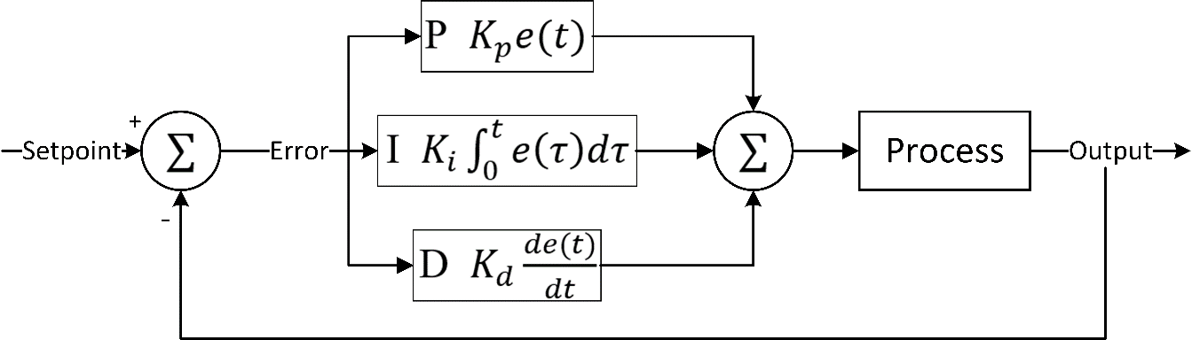
In this section there are many part include, Model of three Phase Induction Motor, Model of PID Controller and Model of neural network controller. To simulate electric motors, the motor is mathematically modeled and constructed by calculating the transfer function. One of the tests that are suggested is controlling the rotational speed or position of the rotor. By representing the motor with a diagram representing the equivalent circuit, the simulation model is designed and analyzed. PID controller, to control the rotational speed of an induction motor when it is within linear system applications. This type of controller succeeds by calculating the error value and calculating it from the comparison of the actual and reference values. The traditional PID controller can be represented as in Figure 1. In this section there are four part include, the first part open loop of induction motor that show in 2.1. Second part close loop of induction motor that show in 2.2. Third part PID Controller for close loop of induction motor that show in 2.3. Fourth part ANN for close loop of induction motor that show in 2.4.
Figure 1. Traditional PID controller
Open Loop of Induction Motor
In this section there are two part include, simulation Model of open loop for induction motor that show in 2.1.1. Second part simulation response of open loop for induction motor that show in 2.1.2.
Simulation Model of Induction Motor
Motor specifications and system characteristics the parameters of the induction motor to be used in the current simulation can be defined, including a 50 Hp induction motor with a frequency of 50 Hz and a voltage from a three-phase supply of 420 V can be seen in Figure 2. To represent the motor with a simulation model to understand the system's behavior under different operating conditions, a mathematical representation is written and the appropriate transfer function [46] is calculated based on the motor parameters in Table 1.
Table 1. Parameters of Induction Motor [46]
Parameter Name | Parameter Symbol | Parameter Value |
Stator Resistance |  (Ω) (Ω)
| 0.288 |
Rotor Resistance |  (Ω) (Ω)
| 0.158 |
Stator Inductance |  (H) (H)
| 0.0425 |
Rotor Inductance |  (H) (H)
| 0.0418 |
Magnetizing Inductance |  (H) (H)
| 0.0412 |
Inertia |  (Kg.m2) (Kg.m2)
| 0.4 |
No. of pole |  (pole) (pole)
| 2 |
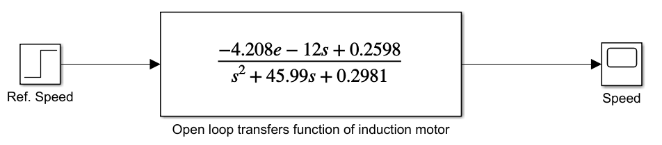
Figure 2. Simulation Model of induction motor with open loop system
| 
| (1) |
Simulation Response of Induction Motor
Using the simulation model in Figure 2, an open-loop system test can be conducted to identify the behavior of the induction motor, and the output signal can be plotted as in Figure 3. In fig.3. show the simulation response of induction motor with close loop system with time running test equal 1500 sec the input and output step per unit but the value in stability system is less than one.
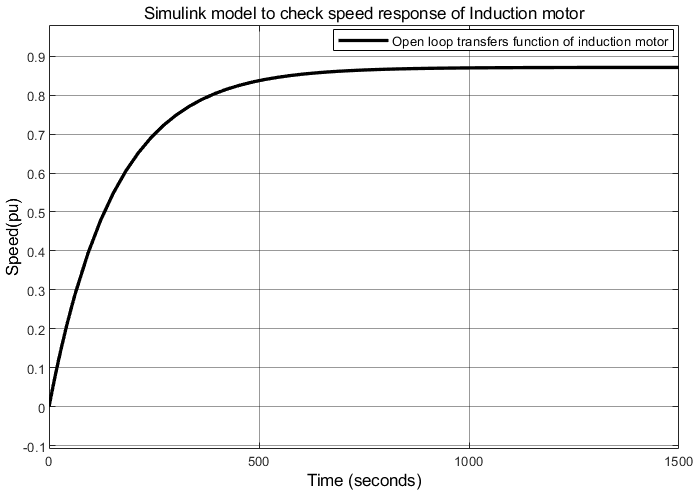
Figure 3. Simulation response of induction motor with open loop system
Close Loop of Induction Motor
In this section there are two part include, simulation Model of close loop for induction motor that show in 2.2.1. Second part simulation response of close loop for induction motor that show in 2.2.2.
Simulation Model of Induction Motor
In the second test, feedback is added to the output signal and compared to the reference input signal, and the error rate between the two signals is identified. The simulation model can also be used as in Figure 4.
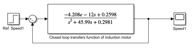
Figure 4. Simulation Model of induction motor with close loop system
Simulation Response of Induction Motor
Using the simulation model in Figure 4, a close-loop system test can be conducted to identify the behavior of the induction motor, and the output signal can be plotted as in Figure 5. In Figure 5 show the simulation response of induction motor with close loop system with time running test equal 1500 sec the input and output step per unit but the value in stability system is less than one.
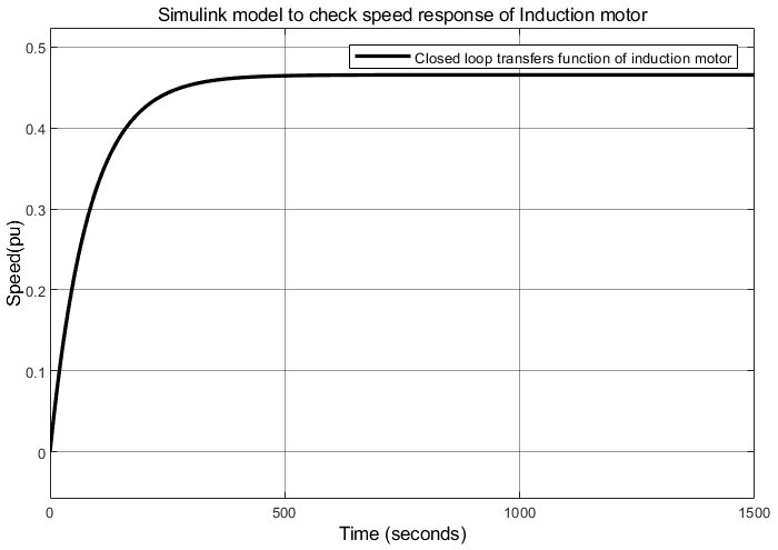
Figure 5. Simulation response of induction motor with close loop system
PID Controller for Close Loop of Induction Motor
In this section there are two part include, simulation Model for PID Controller of close loop induction motor that show in 2.3.1. Second part simulation response for PID Controller of close loop induction motor that show in 2.3.2.
Simulation Model for PID Controller of Close Loop Induction Motor
In the second test, PID Controller and feedback are added to the output signal and compared to the reference input signal, and the error rate between the two signals is identified. The simulation model can also be used as in Figure 6.
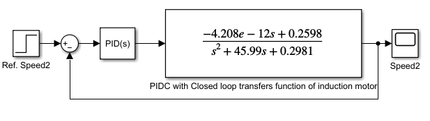
Figure 6. Simulation Model of PID Controller for induction motor
Simulation Response of Induction Motor
Using the simulation model in Figure 6, an of PID Controller for induction motor system test can be conducted to identify the behavior of the induction motor, and the output signal can be plotted as in Figure 7.
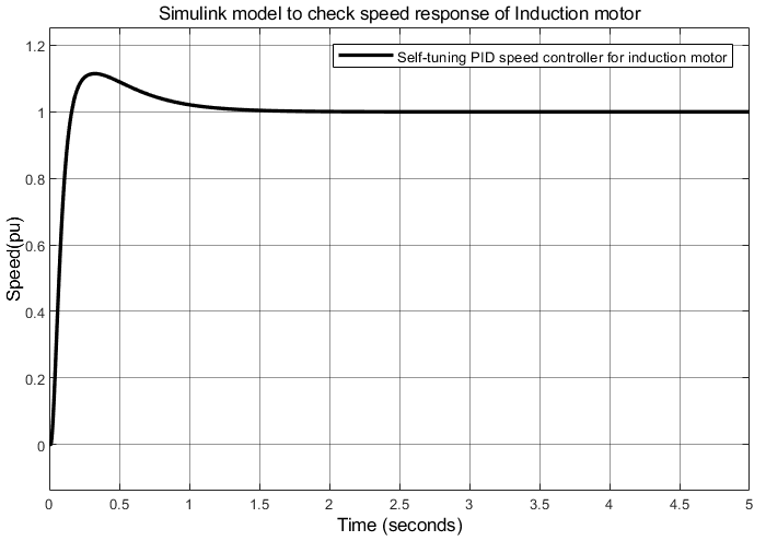
Figure 7. Simulation response of PID Controller for induction motor
ANN for Close Loop of Induction Motor
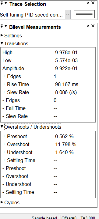
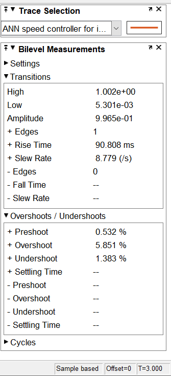
In this section there are three part include, simulation Model for PID Controller of close loop induction motor and simulation Model for ANN of close loop induction motor. PID Controller and feedback are added to the output signal and compared to the reference input signal, and the error rate between the two signals is identified. Also by using ANN of close loop induction motor. The simulation model can also be used as in Figure 8 and Figure 9. Using the simulation model in Figure 8, an of ANN for induction motor system test can be conducted to identify the behavior of the induction motor, and the output signal can be plotted as in Figure 10. In Figure 11 to Figure 15 show the value of tr equal 98.167msec, overshoot equal 11.798% and undershoot equal -1.640% that response for PIDC- IM while in fig.11 b show the value of tr equal 90.808msec, overshoot equal 5.851% and undershoot equal 1.383% that response for ANN – IM.
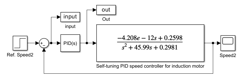
Figure 8. Simulation model of self-tuning PID controller for IM before using ANN with IM
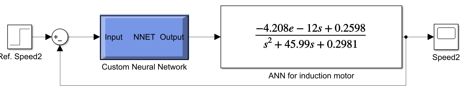
.Figure 9. Simulation model of ANN for IM

Figure 10. Simulation Response of ANN for IM
| 
|
a. PIDC- IM | b. ANN- IM |
Figure 11. Simulation results of overshoot, undershoot & rise time (tr)
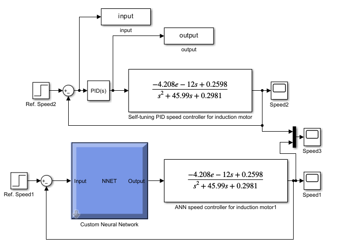
Figure 12. Simulation model for PID controller and ANN of close loop induction motor
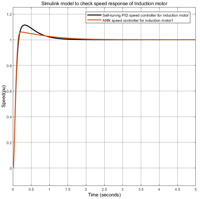
Figure 13. Simulation Response for PID controller and ANN of close loop induction motor
Figure 14. Simulation of ANN training and custom
Figure 15. Simulation of best training performers for ANN
Conclusion
An induction motor (IM) was simulated using a transfer function model with four test cases: open-loop system, closed-loop system without control, closed-loop system with PID, and closed-loop with neural network control. The operating preferences at speed regulation and disturbance rejection. The value of tr equal 98.167msec, overshoot equal 11.798% and undershoot equal 1.640% that response for PIDC- IM while the value of tr equal 90.808msec, overshoot equal 5.851% and undershoot equal 1.383% that response for ANN – IM.The neural network controller reduced overshoot by 6% compared to PID.The neural network controller reduced undershoot by 0.3% compared to PID. Simulation results also indicate that the neural network's rise time (90.808 ms) is 8 ms faster than the rise time of the conventional motor (98.167 ms).
REFERENCES
- H. Maghfiroh, A. Ma’arif, F. Adriyanto, I. Suwarsno, and W. Caesarendra, “Adaptive linear quadratic gaussian speed control of induction motor using fuzzy logic,” Journal Européen des Systèmes Automatisés, vol. 56, no. 4, p. 703, 2023, https://doi.org/10.18280/jesa.560420.
- F. AtaAllah, M. Elsaadany, M. Q. Elahi, S. Mukhopadhyay and H. Rehman, "Nested FOPI and PI Controller Performance Comparison for Electric Vehicle Traction System," in IEEE Access, vol. 13, pp. 63310-63323, 2025, https://doi.org/10.1109/ACCESS.2025.3556174.
- F. N. Abdullah, G. A. Aziz, and S. W. Shneen, “Simulation model of servo motor by using matlab,” Journal of Robotics and Control (JRC), vol. 3, no. 2, pp. 176-179, 2022, https://doi.org/10.18196/jrc.v3i2.13959.
- A. Jaswal, M. Abu-Ayyad, Y. Lad and A. Attaluri, "Stepper Motor Position Control Using PD and MPC Algorithms Embedded in Programmable Logic Controller," in IEEE Access, vol. 13, pp. 39096-39106, 2025, https://doi.org/10.1109/ACCESS.2025.3544509.
- M. H. Setiawan, A. Ma'arif, M. F. Saifuddin, and W. A. Salah, “A Comparative Study of PID, FOPID, ISF, SMC, and FLC Controllers for DC Motor Speed Control with Particle Swarm Optimization,” International Journal of Robotics and Control Systems, vol. 5, no. 1, pp. 640-660, 2025, https://doi.org/10.31763/ijrcs.v5i1.1764.
- S. W. Shneen, H. S. Dakheel, and Z. B. Abdullah, “Design and implementation of no load, constant and variable load for DC servo motor,” Journal of Robotics and Control (JRC), vol. 4, no. 3, pp. 323-329, 2023, https://doi.org/10.18196/jrc.v4i3.17387.
- A. Bandyopadhyay, “Speed Control of Brushless DC Motor Using PI Controller with Fuzzy Logic,’ In International Conference on Industry 4.0 and Advanced Manufacturing, pp. 371-383, 2024, https://doi.org/10.1007/978-981-97-7150-9_31.
- M. I. Abdelwanis, “Optimizing the performance of six-phase induction motor-powered electric vehicles with fuzzy-PID and DTC,” Neural Computing and Applications, vol. 37, no. 16, pp. 9721-9734, 2025, https://doi.org/10.1007/s00521-024-10455-0.
- H. S. Dakheel, S. W. Shneen, Z. B. Abdullah, and A. L. Shuraiji, “Evaluation of Voltage/Frequency and Voltage Source Inverter Control Strategies for Single-Phase Induction Motors Using MATLAB Simulation,” Journal of Robotics and Control (JRC), vol .5, no. 6, pp. 1910-1923, 2024, https://doi.org/10.18196/jrc.v5i6.23760.
- A. M. Putra, H. Maradona, and R. A. Rohmah, “Comparison of Proportional Integral Derivative and Fuzzy Logic Controllers: A Literature Review on the Best Method for Controlling Direct Current Motor Speed,” International Journal of Robotics and Control Systems, vol. 5, no. 1, pp. 240-265, 2025, https://doi.org/10.31763/ijrcs.v5i1.1701.
- A. Ma'arif and A. Çakan, “Simulation and arduino hardware implementation of dc motor control using sliding mode controller,” Journal of Robotics and Control (JRC), vol. 2, no. 6, pp. 582-587, 2021, https://doi.org/10.18196/jrc.26140.
- Z. B. Abdullah, S. W. Shneen, and H. S. Dakheel, “Simulation model of PID controller for DC servo motor at variable and constant speed by using MATLAB,” Journal of Robotics and Control (JRC), vol. 4, no. 1, pp. 54-59, 2023, https://doi.org/10.18196/jrc.v4i1.15866.
- I. D. Kurniasari and A. Ma'arif, “Implementing PID-Kalman Algorithm to Reduce Noise in DC Motor Rotational Speed Control,” International Journal of Robotics & Control Systems, vol. 4, no. 2, 2024, https://doi.org/10.31763/ijrcs.v4i2.1309.
- F. Furizal, A. Ma'arif, D. Rifaldi, and A. A. Firdaus, “Comparison of Convolutional Neural Networks and Support Vector Machines on Medical Data: A Review,” International Journal of Robotics and Control Systems, vol. 4, no. 1, pp. 445-462, 2024, https://doi.org/10.31763/ijrcs.v4i1.1375.
- A. L. Shuraiji and S. W. Shneen, “Fuzzy logic control and PID controller for brushless permanent magnetic direct current motor: a comparative study,” Journal of Robotics and Control (JRC), vol. 3, no. 6, pp. 762-768, 2022, https://doi.org/10.18196/jrc.v3i6.15974.
- Y. Maamar et al., “Design, Modeling, and Simulation of A New Adaptive Backstepping Controller for Permanent Magnet Linear Synchronous Motor: A Comparative Analysis,” International Journal of Robotics and Control Systems, vol. 5, no. 1, pp. 296-310, 2025, https://doi.org/10.31763/ijrcs.v5i1.1425.
- Y. Zahraoui, M. Moutchou, S. Tayane, C. Fahassa, and S. Elbadaoui, “Induction Motor Performance Improvement using Super Twisting SMC and Twelve Sector DTC,” International Journal of Robotics & Control Systems, vol. 4, no. 1, 2024, https://doi.org/10.31763/ijrcs.v4i1.1090.
- S. W. Shneen, Z. B. Abdullah, and H. S. Dakheel, “Design and Implementation of Voltage Source Inverter Using Sinusoidal Pulse Width Modulation Technique to Drive A Single-Phase Induction Motor,” International Journal of Robotics & Control Systems, vol. 4, no. 4, 2024, https://doi.org/10.31763/ijrcs.v4i3.1541.
- N. T. Pham and P. D. Nguyen, “A Novel Hybrid Backstepping and Fuzzy Control for Three Phase Induction Motor Drivers,” International Journal of Robotics & Control Systems, vol. 5, no. 1, 2025, https://doi.org/10.31763/ijrcs.v5i1.1707.
- C. S. Kumar, S. Ravikrishna, P. Rajasekar and M. Venkatesan, “Prognostic Real Time Analysis of Induction Motor,” International Journal of Robotics and Control Systems, vol. 4, no. 1, pp. 139-150, 2024, https://doi.org/10.31763/ijrcs.v4i1.1252.
- G. A. Aziz, F. N. Abdullah, and S. W. Shneen, “Performance Enhancement of DC Motor Drive Systems Using Genetic Algorithm-Optimized PID Controller for Improved Transient Response and Stability,” International Journal of Robotics & Control Systems, vol. 5, no. 1, 2025, https://doi.org/10.31763/ijrcs.v5i1.1602.
- V. Velmurugan, M. Venkatesan, and N. N. Praboo, “Analysis and performance validation of CRONE controllers for speed control of a DC motor,” International Journal of Robotics and Control Systems, vol. 4, no. 2, pp. 558-580, 2024, https://doi.org/10.31763/ijrcs.v4i2.1343.
- N. T. Pham, “Design of Novel STASOSM Controller for FOC Control of Dual Star Induction Motor Drives,” International Journal of Robotics & Control Systems, vol. 4, no. 3, 2024, https://doi.org/10.31763/ijrcs.v4i3.1443.
- Z. A. Al-Dabbagh, and S. W. Shneen, “Design of a PID Speed Controller for BLDC Motor with Cascaded Boost Converter for High-Efficiency Industrial Applications,” International Journal of Robotics & Control Systems, vol. 5, no. 1, 2025, https://doi.org/10.31763/ijrcs.v5i1.1601.
- F. R. Yaseen and H. Al-Khazraji, “Optimized Vector Control Using Swarm Bipolar Algorithm for Five-Level PWM Inverter-Fed Three-Phase Induction Motor,” International Journal of Robotics & Control Systems, vol. 5, no. 1, 2025, https://doi.org/10.31763/ijrcs.v5i1.1713.
- S. W. Shneen and A. L. Shuraiji, “Simulation model for pulse width modulation-voltage source inverter of three-phase induction motor,” International Journal of Power Electronics and Drive Systems, vol. 14, no. 2, pp. 719-726, 2023, https://doi.org/10.11591/ijpeds.v14.i2.pp719-726.
- A. Najem, A. Moutabir, and A. Ouchatti, “Simulation and Arduino Hardware Implementation of ACO, PSO, and FPA Optimization Algorithms for Speed Control of a DC Motor,” International Journal of Robotics & Control Systems, vol. 4, no. 3, 2024, https://doi.org/10.31763/ijrcs.v4i3.1483.
- H. S. Dakheel, Z. B. Abdullah, and S. W. Shneen, “Advanced optimal GA-PID controller for BLDC motor,” Bulletin of Electrical Engineering and Informatics, vol. 12, no. 4, pp. 2077-2086, 2023, https://doi.org/10.11591/eei.v12i4.4649.
- S. E. Mezaache and E. Zaidi, “Performance Enhancement of Dual-Star Induction Machines Using Neuro-Fuzzy Control and Multi-Level Inverters: A Comparative Study with PI Controllers,” International Journal of Robotics & Control Systems, vol. 5, no. 1, 2025, https://doi.org/10.31763/ijrcs.v5i1.1670.
- M. S. Hossain et al., “Performance evaluation of a nearest level control-based TCHB multilevel inverter for PMSM motors in electric vehicle systems,” Results in Engineering, vol. 25, p. 103949, 2025, https://doi.org/10.1016/j.rineng.2025.103949.
- S. W. Shneen, A. L. Shuraiji, and K. R. Hameed, “Simulation model of proportional integral controller-PWM DC-DC power converter for DC motor using matlab,” Indonesian Journal of Electrical Engineering and Computer Science, vol. 29, no. 2, pp. 725-734, 2023, https://doi.org/10.11591/ijeecs.v29.i2.pp725-734.
- Q. S. Kadhim et al., “Optimum design of bearingless brushless DC motor modeling with dual loop controller using dragonfly optimizers,” e-Prime-Advances in Electrical Engineering, Electronics and Energy, vol. 11, p. 100942, 2025, https://doi.org/10.1016/j.prime.2025.100942.
- S. W. Shneen, M. Q. Sulttan, and M. H. Jaber, “Variable speed control for 2Ph-HSM in RGS: a comparative simulation study,” International Journal of Electrical and Computer Engineering, vol. 10, no. 3, p. 2285, 2020, http://doi.org/10.11591/ijece.v10i3.pp2285-2295.
- M. F. Elmorshedy, S. B. Mahajan, S. Vemparala, S. A. Hamad, D. J. Almakhles, and M. W. Lotfy, “An enhanced finite control set model predictive direct thrust control for linear induction motors,” Results in Engineering, vol. 26, p. 104590, 2025, https://doi.org/10.1016/j.rineng.2025.104590.
- S. W. Shneen, H. S. Dakheel, and Z. B. Abdullah, “Simulation and modeling for controlling stepper motor with tuned PID by GWO: comparative study,” Int J Adv Appl Sci ISSN, vol. 2252, no. 8814, p. 8814, 2024, https://doi.org/10.11591/ijaas.v13.i2.pp234-248.
- A. A. Mutlag, M. K. Abd, and S. W. Shneen, “Power Management and Voltage Regulation in DC Microgrid with Solar Panels and Battery Storage System,” Journal of Robotics and Control (JRC), vol. 5, no. 2, pp. 397-407, 2024, https://doi.org/10.18196/jrc.v5i2.20581.
- S. W. Shneen, M. A. A. Hussein, J. A. Kadhum, and S. M. Ali, “Application of LFAC {16 2/3Hz} for electrical power transmission system: a comparative simulation study,” TELKOMNIKA (Telecommunication Computing Electronics and Control), vol. 17, no. 2, pp. 1055-1064, 2019, https://doi.org/10.12928/telkomnika.v17i2.10353.
- H. S. Dakheel, Z. B. Abdullah, N. S. Jasim, and S. W. Shneen, “Simulation model of ANN and PID controller for direct current servo motor by using Matlab/Simulink,” TELKOMNIKA (Telecommunication Computing Electronics and Control), vol. 20, no. 4, pp. 922-932, 2022, https://doi.org/10.12928/telkomnika.v20i4.23248.
- S. W. Shneen, “Advanced optimal for three phase rectifier in power-electronic systems,” Indonesian Journal of Electrical Engineering and Computer Science, vol. 11, no. 3, pp. 821-830, 2018, https://doi.org/10.11591/ijeecs.v11.i3.pp821-830.
- R. F. Nadhim, M. K. Oudah, G. A. Aziz, and S. W. Shneen, “Improving TCP/AQM Network Stability Using BBO-Tuned FLC,” International Journal of Robotics and Control Systems, vol. 5, no. 2, pp. 763-780, 2025, https://doi.org/10.31763/ijrcs.v5i2.1761.
- Y. A. Enaya, A. A. Karim, S. M. Saleh, and S. W. Shneen, “Adapting Wired TCP for Wireless Ad-hoc Networks Using Fuzzy Logic Control,” Journal Européen des Systèmes Automatisés, vol. 57, no. 5, p. 1377, 2024, https://doi.org/10.18280/jesa.570513.
- A. L. Shuraiji and S. W. Shneen, “Fuzzy logic control and PID controller for brushless permanent magnetic direct current motor: a comparative study,” Journal of Robotics and Control (JRC), vol. 3, no. 6, pp. 762-768, 2022, https://doi.org/10.18196/jrc.v3i6.15974.
- M. K. Oudah, S. W. Shneen, and S. A. Aessa, “Reduction of Large Scale Linear Dynamic MIMO Systems Using Adaptive Network Based Fuzzy Inference System,” International Journal of Robotics and Control Systems, vol. 5, no. 2, pp. 678-697, 2025, https://doi.org/10.31763/ijrcs.v5i2.1684.
- Y. A. Enaya, A. A. Karim, M. Q. Sulttan, and S. W. Shneen, “Applying Proportional–Integral–Derivative Controllers on Wired Network TCP’s Queue to Solve Its Incompatibility with the Wireless Ad-Hoc Network,” ITEGAM-JETIA, vol. 10, no. 49, pp. 228-232, 2024, https://doi.org/10.5935/jetia.v10i49.1346.
- S. Waley, C. Mao, and N. K. Bachache, “Biogeography based optimization for tuning FLC controller of PMSM,” In International Conference in Swarm Intelligence, pp. 395-402, 2015, https://doi.org/10.1007/978-3-319-20466-6_42.
- A. Idoko, I. Thuku, S. Musa and C. Amos, “Design of tuning mechanism of PID controller for application in three phase induction motor speed control,” International Journal of Advanced Engineering Research and Science, vol. 4, no. 11, pp. 138-147, 2017, https://doi.org/10.22161/ijaers.4.11.21.
AUTHOR BIOGRAPHY

| Ahlam Luaibi Shuraiji     received the B.Eng. and M.Sc. degrees in Engineering Educational Technology/Electrical Engineering, from University of Technology, Baghdad, Iraq, in 1998 and 2004, respectively, and the Ph.D. degree in electrical engineering from The University of Sheffield, Sheffield, U.K., in 2017.She is currently a lecturer at the University of Technology/ College of Electromechanical Engineering. Her research interests include the design of permanent-magnet machines. She can be contacted at email: 50053@uotechnology.edu.iq. received the B.Eng. and M.Sc. degrees in Engineering Educational Technology/Electrical Engineering, from University of Technology, Baghdad, Iraq, in 1998 and 2004, respectively, and the Ph.D. degree in electrical engineering from The University of Sheffield, Sheffield, U.K., in 2017.She is currently a lecturer at the University of Technology/ College of Electromechanical Engineering. Her research interests include the design of permanent-magnet machines. She can be contacted at email: 50053@uotechnology.edu.iq. |
|
|

| Salam Waley Shneen  Educational Background: July 2016 PhD, Degree in Electrical Engineering-Power Electronic, School of Electrical and Electronic Engineering, Huazhong University of Science and Technology (HUST). Nov 2005 MSc, Degree in Engineering Educational Technology-Electrical Engineering, Technical Education Department, University of Technology, Iraq-Baghdad. July 1998 BSc, Degree in Electrical Engineering and Education, Technical Education Department, University of Technology, Iraq- Baghdad. Oct 1994 Diploma in Electrical Technology, Technical Instructors Training Institute, Iraq Baghdad. 1992 High School Bakaloria Degree Preparatory Technical School (Electrical Section), Almashtal Technical Secondary School Iraq-Baghdad. Work Experience 1998-2005 Engineer in: Electronic Lab., Digital Electronic Lab., Communication Lap., Fundamental of Electric Engineering Lab. Cad Lab. In Technical Education Department, University of Technology, Iraq-Baghdad. 2005-2016 Assistant Lecturer in: Electronic Lab. Lecturer Advanced Electronic, Lecturer Fundamental of Electric Engineering, Technical Education Department, Electromechanical Department University of Technology, Iraq-Baghdad. 2016- 2017 Lecturer in: Electronic Lab. Fundamental of Electric Engineering Lab., Lecturer Electronic Circuits, Lecturer Fundamental of Electric Engineering with Electrical and Electronic Circuits Electromechanical Department University of Technology, Iraq-Baghdad. 2017-- today Lecturer in: Energy and Renewable Energies Technology Center, University of Technology, Iraq-Baghdad. He can be contacted at email: salam.w.shneen@uotechnology.edu.iq or salam_waley73@yahoo.com. Educational Background: July 2016 PhD, Degree in Electrical Engineering-Power Electronic, School of Electrical and Electronic Engineering, Huazhong University of Science and Technology (HUST). Nov 2005 MSc, Degree in Engineering Educational Technology-Electrical Engineering, Technical Education Department, University of Technology, Iraq-Baghdad. July 1998 BSc, Degree in Electrical Engineering and Education, Technical Education Department, University of Technology, Iraq- Baghdad. Oct 1994 Diploma in Electrical Technology, Technical Instructors Training Institute, Iraq Baghdad. 1992 High School Bakaloria Degree Preparatory Technical School (Electrical Section), Almashtal Technical Secondary School Iraq-Baghdad. Work Experience 1998-2005 Engineer in: Electronic Lab., Digital Electronic Lab., Communication Lap., Fundamental of Electric Engineering Lab. Cad Lab. In Technical Education Department, University of Technology, Iraq-Baghdad. 2005-2016 Assistant Lecturer in: Electronic Lab. Lecturer Advanced Electronic, Lecturer Fundamental of Electric Engineering, Technical Education Department, Electromechanical Department University of Technology, Iraq-Baghdad. 2016- 2017 Lecturer in: Electronic Lab. Fundamental of Electric Engineering Lab., Lecturer Electronic Circuits, Lecturer Fundamental of Electric Engineering with Electrical and Electronic Circuits Electromechanical Department University of Technology, Iraq-Baghdad. 2017-- today Lecturer in: Energy and Renewable Energies Technology Center, University of Technology, Iraq-Baghdad. He can be contacted at email: salam.w.shneen@uotechnology.edu.iq or salam_waley73@yahoo.com. |
Ahlam Luaibi Shuraiji (Analysis of Improve Performance and Dynamics of an Induction Motor using an Artificial Neural Network Controller and a Conventional Proportional Integral Derivative Controller)