ISSN: 2685-9572 Buletin Ilmiah Sarjana Teknik Elektro
Vol. 7, No. 3, September 2025, pp. 362-381
Design and Implementation of PID Controller for Phase Shifted Full Bridge DC-DC Converter
Luay G. Ibrahim 1, Salam Waley Shneen 2
1 College of Electrical Engineering, University of Technology–Iraq, Baghdad, Iraq.
2 Energy and Renewable Energies Technology Center, University of Technology–Iraq, Baghdad, Iraq.
ARTICLE INFORMATION |
| ABSTRACT |
Article History: Received 28 May 2025 Revised 09 July 2025 Accepted 25 July 2025 |
| 
The study aims to evaluate the converter's operation and how to improve it, and to discuss the performance and behavior of the system in transient and steady states. Phase shifted full bridge DC-DC Converter (PSFB), converter is one of the most popular isolated converter, which is widely used in many applications. So today we are discussing its working, design and MATLAB simulation. converters are used frequently to step down high dc voltages to lower voltages. It also provides isolation between input and output stages. it is major application includes, server power supply, telecom rectifier, battery charging system and renewable energy systems. This is the basic structure of a full bridge DC-DC Converter. we have a dc voltage source at the input. there are the power electronic switches, which can be either MOSFET or IGBT. this is a high frequency transformer. used for the isolation between input and output stages. it also provides the required voltage gain. an inductor is used to limit the output current ripple, and a capacitor used as the filter to regulate the output voltage. To meet the necessary demand, in addition to regulating the quality of electrical power to address the changes and fluctuations in the system caused by various factors, the output of the converters is enhanced by developing a model design through simulation to provide the appropriate voltage, current, and power to cover the required load. Industrial applications are among the most important industries that employ and use electronic power converters, including the DC-DC converter, especially the PSFB. Among these applications are charging systems for storage units in electricity generation systems from renewable energies, including solar or wind energy, with a DC generator. It can also be part of a lighting system or microgrids, as this converter is characterized by high efficiency in performance, quality, and reliability, and has the advantage of a wide range at high frequencies. The PSFB converter consists of a DC source to supply a DC load, connected to an inverter on the source side and a filter on the load side, with a rectifier between them. The rectifier is a bridge type of four diodes, the inverter is a bridge of four MOSFET transistors, and the LC filter consists of a coil and a capacitor. Among the areas that require a wide frequency range are communications systems, which is one of the most important applications and areas of use for this converter. |
Keywords: DC-DC Converter; PID Controller; Voltage Regulation; Renewable Energy Systems; PSFB |
Corresponding Author: Salam Waley Shneen, Energy and Renewable Energies Technology Center, University of Technology –Iraq. Email: salam.w.shneen@uotechnology.edu.iq |
This work is open access under a Creative Commons Attribution-Share Alike 4.0 
|
Document Citation: L. G. Ibrahim and S. W. Shneen, “Design and Implementation of PID Controller for Phase Shifted Full Bridge DC-DC Converter,” Buletin Ilmiah Sarjana Teknik Elektro, vol. 7, no. 3, pp. 362-381, 2025, DOI: 10.12928/biste.v7i3.13814. |
INTRODUCTION
Electrical power systems are a matter of interest due to the ongoing advancements in sustainable development. Renewable energy sources enhance the possibility of improving a clean and environmentally friendly working environment. The issue of generating electricity from various sources, including renewable energy such as wind and solar, is also a major topic requiring further research and analysis. Systems have parts, and their components are interconnected within these systems during the generation, transmission, and distribution processes. Transformation systems are an important component, as they come in various types, including transformers that increase power and others that decrease power. There are also three-phase transformers, single-phase transformers, and other classifications based on the power supply and transformer output. Transformers convert a fixed quantity into a variable quantity, such as a DC-DC converter, including phase-shifted full bridge (PSFB) transformers. A PSFB is a converter consisting of a source voltage inverter (DC to AC) of a bridge type with four MOSFET transistor switches. In addition to the inverter, there is a transformer connected to the inverter on one side and to the rectifier on the other side, which is another type of converter (AC to DC). This converter (PSFB) is characterized by easy isolation and other features such as the ability to switch smoothly and switch at zero voltage (ZVS). ZVS makes the converter robust and highly efficient, with a highly efficient output compared to other converters. Many applications require smooth switching rather than hard switching, as well as galvanic isolation and ease of control. These features are available in this converter, in addition to the ability to easily control using pulse width modulation (PWM) technology. These features can make it a successful choice in many applications such as server sources in communications systems. In high-power systems, it is more efficient than half-bridge converters and has higher insulation and losses [1]-[3].
PSFB inverters are also preferred over conventional full-bridge inverters (FBIs) because they have lower losses. Compared to the other type of inverter preferred for charging, the direct active bridge (DAB) inverter, despite its bidirectional operation (power flows in both directions), PSFB inverters have fewer components and are easier to control. PSFB inverters are considered a preferred choice for both current and future applications because they offer a good balance in medium to high power scenarios [4]-[6]. To build and represent a simulation model that helps determine system behavior, analyze converter operation, and verify its effectiveness, MATLAB can be used to model and simulate a PSFB inverter, one of the most important phase-shifted DC-DC bridge inverters. The components of this model can be defined through the simulation environment, which consists of a converter with a rectifier, electronic switches, and a filter. The model contains parameters including the transformer transformation ratio and the switching frequency. The number of transformer turns is the factor affecting the transformation ratio between the two terminals of the transformer. Model parameters also include phase angle and leakage inductance. These factors affect the performance measurement and behavior modification process, determining the effectiveness of the PSFB converter. A full-bridge phase-shifted DC-DC converter can be effectively modeled and simulated using the MATLAB Simulink environment. Simulink provides tools for representing converter components (switches, transformer, rectifier, filter) and implementing control strategies. Key parameters include switching frequency, converter turns ratio, leakage inductance, and phase shift angle, all of which affect converter performance. The system model consists of a full-bridge inverter, which can be built using metal-oxide-semiconductor field-effect transistors (MOSFETs), thyristors, or insulated-gate bipolar transistors (IGBTs). The inverter is represented by four electronic switches, such as MOSFETs. The electronic switches can be turned on and off using the gate voltage [7]-[9].
PWM (pulse-width modulation) technology can control the inverter's on and off periods and determine the appropriate output. The model also consists of a convertor, which uses the leakage inductance and number of turns of the primary and secondary windings to determine the desired transformer output. The transformer input is connected to the inverter output, while the transformer output is connected to the rectifier input. In addition to the inverter and transformer, another component of the PSFB converter is the rectifier, which is connected to the transformer output from the secondary winding. This rectifier is represented by four bridge-tuned diodes. The rectifier output is connected to an LC-pass filter, which filters the rectifier output. The PSFB converter requires control systems to adjust the duty cycle, adjust the phase shift, and regulate the operation of the closed-loop system, which includes feedback to help regulate the output using a voltage-mode control (VMC) or peak-current-mode control (PCMC) system. Various operating conditions can be adopted, under which the behavior of the system (the PSFB converter) is analyzed, including changes in input voltage, changes in load, and other parameters. The analysis includes input and output waveforms for each phase of the converter for electrical quantities including voltage and current for each electronic switch, inverter terminal, converter terminal, and rectifier terminal. Performance quality and reliability can be determined by evaluating the converter's efficiency and transient response, in addition to voltage regulation and power loss coefficient. To improve performance, an advanced converter design can be developed, in which the transformer's transformation ratio depends on the optimal values for the number of transformer turns and leakage inductance for different applications. The electronic switch operates like a MOSFET transistor with a switching frequency between the on and off states in the inverter model, which improves performance and reduces switching losses. The output voltage ratio of the transformer can be determined by determining the ratio of the turns of the secondary and primary coils. The leakage inductance between the two coils determines the magnetic field of the transformer to achieve the proper switching, which is zero voltage switching (ZVS). The phase shift angle (Φ) can be controlled by the trigger signals of the electronic switches. To transmit power in the transformer, the switching angles and signals of the electronic switches are controlled through the switching time intervals of these switches. This prevents leakage current during the switching and stopping times [10]-[12].
METHODOLOGY OF PSFB CONVERTOR
The operation of the PSFB convertor can be described in time and periods during the transient and steady state through linear operation, i.e. without a change in the load. The behavior of the system can be identified at the steady state, where the transformer and electronic switches operate and switch at zero voltage (ZVS). Steady-state operation shows the output of the transformer, the isolation, and the output of the transistors, as well as the input and output voltages, the voltage of the rectifier, the inverter, and the filter, i.e. all the terminals of the system components. Whereas when the other system state, the transient state, is desired, the load is changed, and from this the behavior change becomes clear as a result of a change in the system parameters, and consequently the readings of the devices change. The change resulting from the transient state requires the implementation of feedback, which is part of the closed-loop system, as well as a control unit that regulates the output of the transformer to meet the requirements of the change in the load and return the system from the transient state to the steady state. Control and output regulation require rapid response and handling of changes in system parameters. For example, current values may be affected by load changes, which can lead to current bias problems. Improving performance requires rapid handling of current bias. Reducing bias requires developing and implementing a control strategy, including pulse width modulation (PWM), the use of various control modules, and active clamp circuits. The PSFB converter has the advantages of ZVS operation, most notably its precise design and high efficiency due to low switching losses. One potential contribution of this work is the analysis of phase shift versus reference voltage analysis [13]-[15]. PSFB is used as a DC to DC converter as is the conventional FB type and both are considered high level power converters but there is an advantage in converting through switching with zero voltage and without zero voltage which is an advantage that gives high efficiency by reducing switching losses of electronic power switches when working at high frequencies [16]-[20].
The importance of using electronic power devices (diode, transistor, thyristor) in building circuits called electronic power circuits (power electronic convertor) according to the input and output of the circuit is highlighted. When do we need electronic power circuits when there is a difference between the type and quantity of the supply source and the load to be fed. There are two types of sources in terms of the type of current, including direct current sources and others alternating current sources. There is another classification according to the number of phases, including single phase and three phase. Loads can also be the loads need to be fed with a direct current, a single-phase alternating current, or a three-phase alternating current. It can be a supply source of the first type, which is a constant current source with a fixed value, and the loads need to be fed with a fixed or variable value that is higher or lower than the source voltage. In the current case, we need to build a model of an electronic power circuit that meets the demand, and it can be called according to the case. The types called direct current converters or (DC/DC Converters) that have a direct current input and a direct current output can be divided into three types, including voltage-reducing direct current type converters, a current converter of the first type called (Buck Converter). The second one is considered a voltage booster and is called (Boost Converter). The third can be called the Buck - Boost Converter [21]-[24].
There is also another case that depends on feeding from a direct current source (solar cells or batteries) that differs from the first type in that its loads require alternating current type feeding and may be single-phase or three-phase. The current situation requires the need to build a different model for a power circuit. An electronic device with a direct current input and an alternating current output. The model can be designed and built according to the number of phases and the required voltage. Some of them are suitable for building a single-phase electronic power circuit and are called a single-phase inverter and the other is a three-phase inverter. There can be two other cases for an alternating current power source (the network). The national generation station and renewable energies, such as wind, feed alternating current loads or direct current loads. When the supply source and the load are of the same type, the input is alternating current and the output is fixed or variable. The fourth type of electronic power circuits is the unified one, as it has an alternating current input and a direct current output [25]-[28].
Currently, work is underway to build a simulation model using both open-loop mode for the proposed converter. A prototype can be constructed by schematically representing it, first, with a DC power source connected to a bridge converter consisting of four MOSFET switches. This circuit, which is part of the system, outputs a waveform with the same voltage value but with two periodic intervals, giving a positive half value for the first period and a negative half value for the second period, due to the operation of the electronic switches. In the first period, a positive output voltage value is obtained when switches 1 and 3 are in the "on" state, while switches 2 and 4 are in the "off" state during the same period. In the second period, the opposite occurs, such that a negative output voltage value is obtained when switches 1 and 3 are in the "off" state, while switches 2 and 4 are in the "on" state during the same period. In the current simulation, a voltage transformer is added from high voltage to low voltage, for example, from 400 V to 12 V or from 600 V to 12 V. The source voltage is connected to a single-phase bridge inverter, and the inverter output is connected to a linear transformer. The phase shift occurs at the input side of the transformer, which is the same as the output side of the inverter. By changing the reference voltage value, the phase shift can be detected. The transformer output, i.e. the secondary winding terminals, is connected to a voltage rectifier to convert the alternating current to direct current, which is then fed to the load. The present study presents a simulation model of Phase shifted full bridge DC-DC Converter (PSFB) and its contributions include studying the phase shift change with the change of the reference voltage. This is verified by proposing test cases that include four output values of 2, 4, 10 and 12 V with an input voltage of 400 V. From the simulation results, the relationship between the possibility of changing the phase shift and the current change on the one hand and the change of the reference voltage of the output voltage on the other hand can be observed.
High-voltage direct current (HVDC) uses relatively high amounts of DC voltage, up to 400 volts or higher, as in industrial applications. This voltage can be supplied from a renewable energy source such as a wind turbine with a DC generator, or from a solar power source. Other systems, such as computers, require a lower voltage, and therefore converter output values are adopted. These converters are designed to provide a voltage suitable for the operation of certain system components, such as a converter output voltage of approximately 2 volts, 6 volts, 10 volts, 12 volts, etc. High input voltages can be selected to generate and transmit power efficiently, while reducing the current requirements for the same power and transmitting it over relatively long distances. Converter outputs can be used to meet the requirements of targeted applications for readily available components that require standard amounts of converter output voltage [29]-[31]. In methodology of PSFB section there are three parts, include, first part called system description that show in section 2.1, second part called system working that show in section 2.2 and third part called design system that show in section 2.3 bellow:
Description of PSFB
An important application is environmentally friendly industrial systems. The design and operation of the storage unit (battery) charging system in an electric vehicle is a matter of interest to specialists, academics, and relevant institutions. The charging system requires electronic power converters to provide the appropriate charging voltage to the battery. The converters used are full-bridge, phase-shifted converters. They consist of four switches with on-off periods that depend on the switching frequency, some of which are soft-switching and others hard-switching. Some circuits and loads require an appropriate voltage, including sub-circuits and main circuits, and the voltage value may differ, requiring the use of appropriate strategies and techniques. For example, when there is a suitable high voltage of 400 or 600 volts to operate and rotate the electric motor to cover the main loads, to operate an electric vehicle, there is also a need for a low voltage, for example, 12 volts, to operate sub-loads such as wipers and opening and closing windows. Based on the above, it can be argued that adding a voltage converter from high voltage to low voltage, for example, from 400 volts to 12 volts or from 600 volts to 12 volts, is important. As a research contribution, the focus is on building a prototype of the system, writing the appropriate mathematical relationships for the system, and calculating the required parameters to obtain a step-down converter of the type of electronic power converter, a full bridge, phase-shifted, with the above quantities, which is suitable for an electric car battery charging system or any other application where the same quantities are available at the input and output of the system [32]-[34].
Working of PSFB
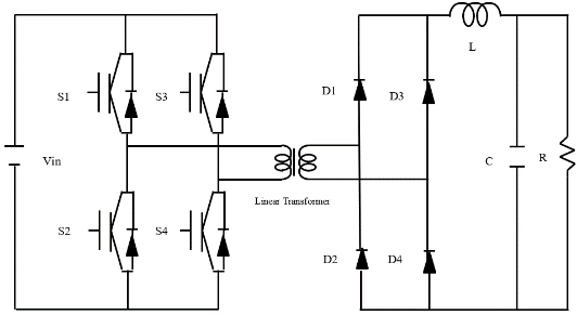
Figure 1 represents the components of the proposed system which can help in writing the appropriate mathematical relationships to design an effective model. By tracing the model, the system components' waves and signals can be represented. These include: First, the trigger pulses of the electronic switches to identify their operating periods when the switch is on and off, as in Figure 2. Second, the transformer output waveform resulting from switch operation, how to obtain the positive and negative halves to be connected to the transformer at both ends of the primary coil, as in Figure 3. Third, the output waveform of the step-down transformer at both ends of the secondary coil, which is connected to the input of a bridge transformer consisting of four diodes connected to the LC filter on the output side, as in Figure 4. The output waveform at a specific load associated with the filter output. In other forms, the current wave can be drawn for each branch within the study limits, such as the inductor current as in Figure 5 and the load current as in Figure 6, in addition to the current drawn from the power source as in Figure 7. The system efficiency can be calculated and drawn with the input and output power in other forms. In other forms, the power wave can be drawn for the system output as in Figure 8 and the output power as in Figure 9, in addition to the efficiency as in Figure 10. From the system diagram (Figure 1), there can be two modes, the first when switches 1 and 3 are on and the second when it is off while the output of this mode is positive. On the other hand, switches 2 and 4 are in the opposite state of switches 1 and 3 to give a negative output, where the operating time is a positive part due to the action of switches 1 and 3 as in the first mode, and another case in the second half of the cycle operating time is a negative part due to the action of switches 2 and 4.

Figure 1. Block diagram for circuit of Phase shifted full bridge DC-DC Converter (PSFB)system
Design of PSFB
Improved and efficient power converters are a subject of widespread interest in various fields, requiring analysis and design of models to ensure the selection of appropriate components. This selection is based on experience, using simulation as a method and strategy that has proven to be appropriate through previous studies by specialists from around the world [35]-[37]. In this study, a simulation model of a step-down DC-DC power converter, called a phase-shifted bridge converter, is presented. The model examines design considerations and calculates system parameters for a converter with a power of (480, 600) and a high input voltage of (600, 400) converted to a low output voltage of (12) and with converter switches operating at a frequency of (250,100) kHz. The proposed converter was designed, modeled, and validated by comparing it with the theoretical design. As a research contribution, the effect of changing the solution on the output current can be studied, thus obtaining the converter efficiency in both cases, and identifying the impact of this on efficiency [38]-[41].
Where the values of the system were  =600Volt,
  =12Volt,
  = 480watt, switching frequency = 250KHZ,
  = 20% and
  = 1%.
= 1%.
As a result of advances in modern technology, there is a focus on conducting studies on environmentally friendly systems that reduce the impact of gas emissions, such as using electric cars instead of fuel-powered ones. In addition to their environmental friendliness, electric cars are distinguished from cars by their relatively high efficiency and low noise, which has attracted the attention of relevant institutions, including industrial companies and specialized researchers. Electric cars operate on main and subsidiary systems. These include main loads, such as the electric motor, which requires high voltage to operate, while subsidiary loads, such as wipers and opening and closing windows, require the addition of electronic power transformers to provide voltage to the subsidiary loads. Electronic switches are used to build electronic power transformers, and by operating these switches at a specific frequency to close and open the switches, the desired output can be achieved.
To ensure proper load operation, factors such as the application's requirements, balancing size and efficiency, ripple limits, and electromagnetic interference (EMI) are considered, along with the adoption of an appropriate switching frequency. Frequency limits can be set as a design criterion, affecting the ripple factor and component size to address and optimize the transformer's response to electromagnetic interference (EMI), at the expense of higher switching losses with voltage and current fluctuations. For example, at a switching frequency of 100 kHz, switching losses are lower, efficiency is higher, and EMI is lower when operating within specific frequency ranges. Another example is at a switching frequency of 250 kHz, where switching losses are higher, passive components are smaller, response speed is faster, and EMI is increasing. EMI can be managed by using a pass-through filter within appropriate ripple limits, which are approximately (20% current, 1% voltage), meaning that the difference between the output current and the average DC current is 20%. Ripple is acceptable for some applications, but it can cause problems in some sensitive electronic circuits. This means that an AC output current of 1% of the DC current is adequate for stable operation of sensitive loads. Sensitive loads include microprocessors and radio frequency circuits, which require ripple at low voltages, while high-current ripple increases power losses in the load [42]-[47].
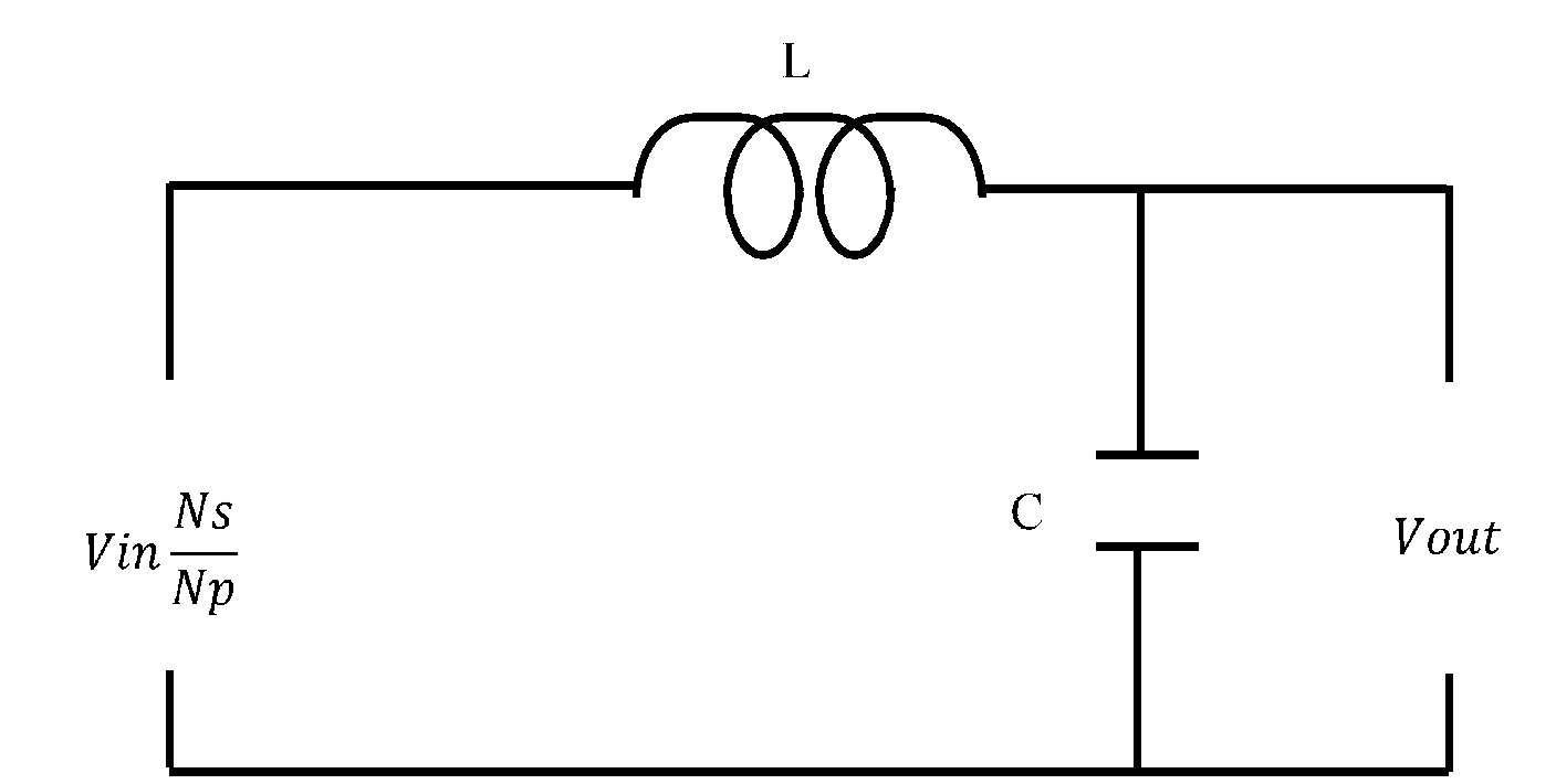
Figure 2. Block diagram of LC filter circuit for Phase shifted full bridge DC-DC Converter (PSFB)system
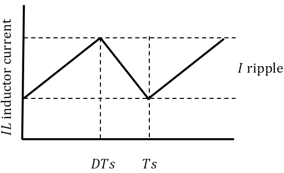
Figure 3. Relationship between and
and  with
with  &
& 
SIMULATION MODELING AND SIMULATION RESULTS OF PSFB
In this section there are two parts include first the simulation modeling of Phase shifted full bridge DC-DC Converter (PSFB) that in section 3.1. Second, the simulation Results of Phase shifted full bridge DC-DC Converter (PSFB) that in section 3.2.
Simulation Modeling of PSFB
The converter's high efficiency, isolation features, and smooth switching make the PSFB converter capable of handling high-voltage power systems, most notably those powered by renewable energy, including solar energy, and how to integrate it into the grid. These features also make this converter safe and reliable for renewable energy systems [48]-[50]. There are many sources for generating electrical energy, including environmentally friendly sources called renewable energy sources. These can be connected to a small grid, connected to the main grid, or isolated from it. Electrical energy sources are used to operate various types of electrical loads such as lighting, electrical appliances, and others in various applications and fields such as industrial, military, and domestic. Energy sources are connected to the loads directly or via transformers, and they can also be used to charge energy storage units. Electronic power converters exist to convert the available quantities into the required quantities appropriate to cover these loads. Environmental conditions change, thus affecting the amount of energy generated, making them unstable sources, as unstable energy generation sources cannot be directly connected to the grid. Therefore, power quality must be regulated by connecting suitable transformers that address this problem, as the transformer input varies due to changing generation conditions, and the transformer's average output voltage is managed and adjusted to meet the demand at the appropriate value. Transformers are also used with charging systems for storage units such as batteries. Among these transformers is the full-bridge phase-shift transformer, which consists of four electronic switches such as thyristors or transistors. Transformer performance evaluation is conducted by proposing prototype specifications and a simulation, and identifying the system's performance and behavior through an appropriate operating time to achieve a suitable phase shift and output according to load requirements. The research contribution is to evaluate the PSFB performance improvement and verify the transformer's output voltage [51]-[55].
Electronic power transformers are used in many applications, including industrial ones, where they offer improved performance and the ability to control the output of the transformer by operating electronic switches. The output of the transformer is controlled by the opening and closing of these switches. Pulse width modulation (PWM) technology determines the periodic opening and closing of the electronic switches. Electronic transformers consist of four switches connected in a bridge manner. The input side is connected to the power source, and the output side is connected to the load. A filter can be added to eliminate harmonics and obtain a pure output signal, thus improving the quality and efficiency of the system. The system can be simply described as a structural structure consisting of a power source symbolized by VS, and a source voltage inverter consisting of four switches symbolized by S and numbered from 1 to 4. There is also a linear transformer consisting of a primary coil connected to the output terminals of the electronic power transformer, while the secondary coil terminals are connected to the filter input consisting of a boost inductor L and a filter capacitor C. The filter output is connected to the resistance representing the load R. The system is operated and its operation depends on the operation of electronic switches, which have an on-off period for each switch during a single cycle, and their operation can be regulated using pulse width modulation technology [56]-[60].
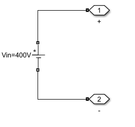
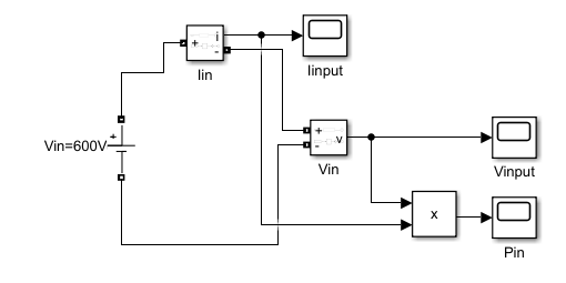
Figures between Figure 4 to Figure 9 are show the first, simulation part include the DC Voltage source, there are two values can be used in this work suggested the high voltage battery (400,600) connected to main power circuit that in Figure 4. Second, simulation model of square wave generator (Inverter) for PSFB that in Figure 5. Third, simulation model of Linear Transformer for PSFB that in Figure 6. Forth, simulation model of Rectifier for PSFB that in Figure 7. Fifth, simulation model of filter for PSFB that in Figure 8. Sixth, simulation model of Load for PSFB that in Figure 9. Seventh, Simulation modeling of Phase shifted full bridge DC-DC Converter (PSFB)that in Figure 10.
| 
| 
|
a. subsystem of DC Voltage source | b. at 600 volts without sensors | c. at 400 volts without sensors |
| 
|
d. at 600 volts with sensors | e. at 400 volts with sensors |
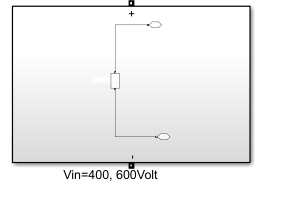
Figure 4. Simulation model of DC Voltage source (high voltage battery 400 and 600 Volt) for PSFB
Figure 5. Simulation model of square wave generator (Inverter) for PSFB
Figure 6. Simulation model of Linear Transformer for PSFB
Figure 7. Simulation model of Rectifier for PSFB
Figure 8. Simulation model of filter for PSFB
Figure 9. Simulation model of Load for PSFB
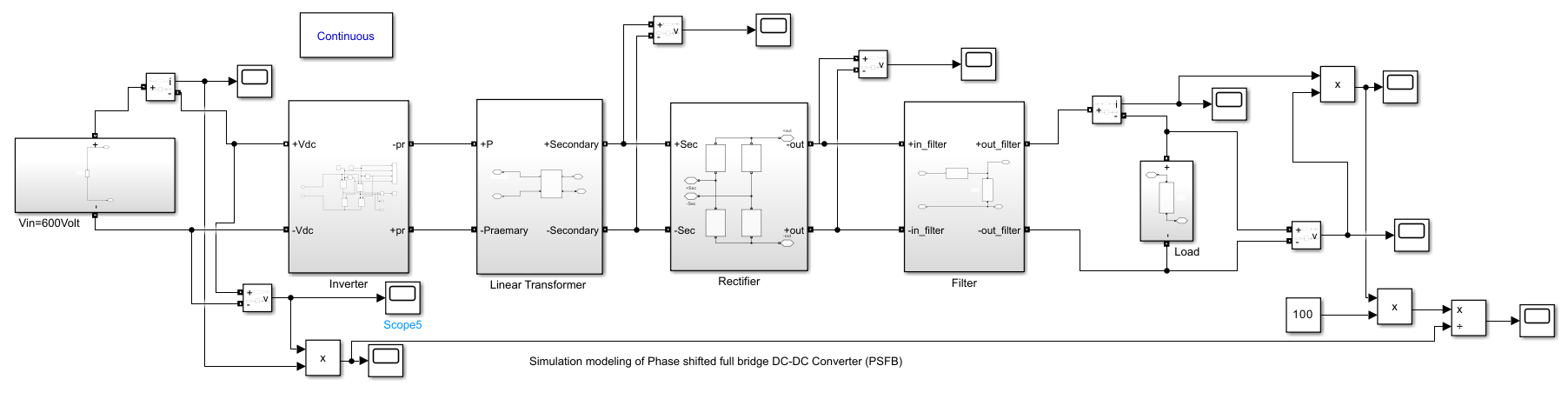
Figure 10. Simulation modeling of Phase shifted full bridge DC-DC Converter (PSFB)
Figure 4 shows a DC power supply for both the 400V and 600V proposed test cases. It also shows a model of a voltage, current, and power sensor to measure the system input voltage in volts, the input current in amperes, and the power of the supply in watts. Figure 5 shows a bridge-type voltage inverter source with four MOSFET transistor switches and a switch trigger pulse signal generator. Figure 6 shows a transformer with a primary winding that can be connected to the inverter output. The secondary winding has terminals that can be connected to the rectifier. Figure 7 shows a bridge rectifier with four diodes that converts AC to DC. The rectifier input is connected to the converter 's secondary winding, while the rectifier output is connected to a filter. Figure 8 shows an LC filter whose output is connected to the load. Figure 9 has a resistive load that can be connected to the filter output. The load voltage and current can be measured, and the output power and efficiency can be calculated. Figure 10 represents the connection diagram of all the components of the PSFB converter. Open-circuit tests at a source voltage of 400 V using pulse width modulation (PWM) to vary the output voltage that in Figure 11. Closed-circuit tests at a source voltage of 400 V using Proportional-Integral-Derivative (PID) controller to vary the output voltage that in Figure 12.
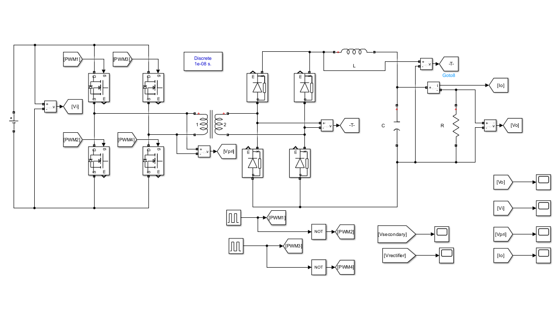
Figure 11. Simulation model for open-loop of PSFB system
Suggested test cases, includes two main test cases based on the source voltage. For each main case, there are subtest cases based on the reference output voltage, which can be used to control the transformer's phase shift. Paragraph 1: When the source voltage is 400 volts, considerations were made for phase shift changes when the system's output reference value changed. There are initial test cases for a single operating period, each with a single output value, including a reference value of 2 volts. Another test case was 6 volts, while the third case was 10 volts, and the fourth 12 volts, which is the system's design value. Another test case divides the operating period into multiple periods, using the same values above for part of that period. Paragraph 2: When the source voltage is 600 volts, using the same method as above to identify the difference in electrical quantities. Using the results of the previous cases, the system signals can be plotted at each part of the system and the values recorded.
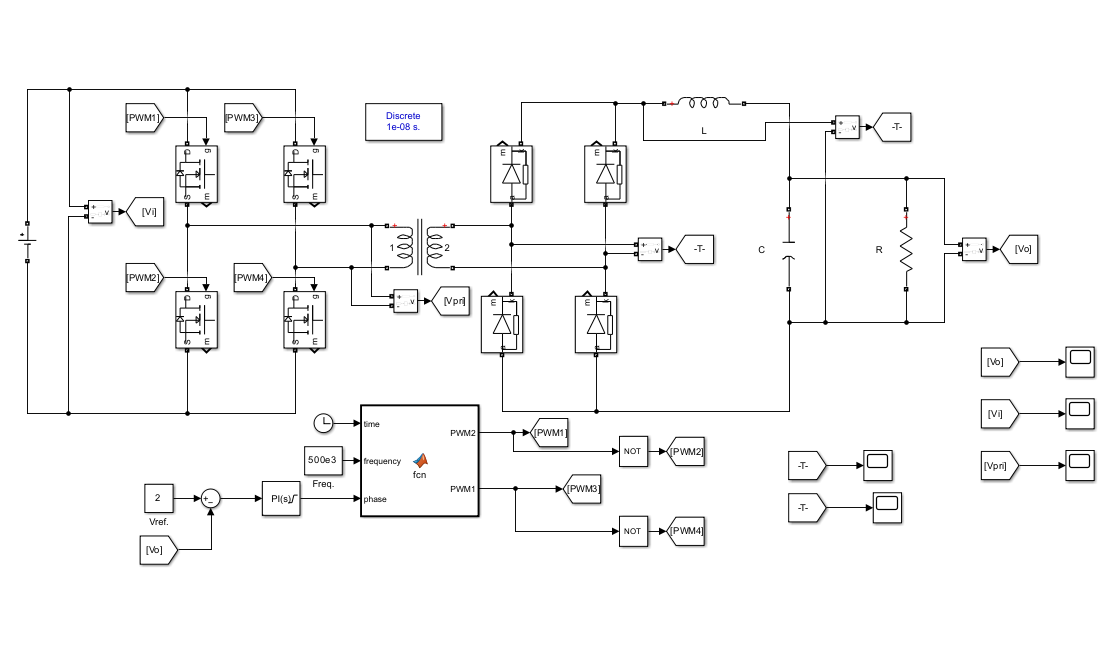
Figure 12. Simulation model for closed-loop of Phase shifted full bridge DC-DC Converter (PSFB) system using Proportional-Integral-Derivative (PID) controller
Simulation Results of PSFB
A simulation of a full bridge phase shift converter is proposed which can be operated from a constant 400 V DC source. The source voltage is fed to a voltage inverter which operates using four switches (S1, S2, S3 and S4) to obtain a time-varying voltage, with a positive voltage of (+400 V) in the first half and a negative voltage of (-400 V) in the second half. The output of the inverter is taken as the input voltage of the linear transformer from the primary winding, and the voltage is stepped up or down according to the load requirements. A pulse voltage is obtained and applied to the primary winding as a result of opening and closing the four switches, and it can be phase shifted as required by controlling the desired output feedback value. A rectifier is connected and added to the transformer output from the secondary coil using a full wave bridge rectifier with four diodes (D1, D2, D3, and D4) to rectify the output voltage. To filter the rectifier output, an LC filter (inductor L and capacitor C) is added and connected to obtain a DC output to supply the load with a voltage of 12 volts. A full bridge converter (FBC) consists of four transistors acting as electronic switches, with the input voltage being the same as the switch voltage. The switches operate as a couple and are controllable. For example, the transformer terminals (primary coil) are powered by the source voltage VS when S1 and S4 are on. During the same period, diodes D1 and D4 are in forward bias (conducting). While during the second period, the opposite is true. During the first period, i.e., the negative half-life, is at -VS when S2 and S3 are on. During the same period, diodes D2 and D3 are in forward bias (conducting).
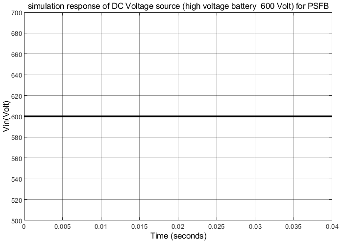
It is proposed to present one of the methods used to supply some systems with the required voltage. Choosing a method requires specifying the supply voltage, i.e., the input voltage, estimated at 400 volts. The system output is also set at 12 volts. Other values can be chosen during testing to identify how the phase shift changes by changing the system output reference value. An output voltage sensor is installed, and the sensor output is connected to a comparator, setting a reference value to determine the error value. This value is passed through a control unit to eliminate the error and obtain the required phase shift. This value is determined using the pulse width modulation technique of the on/off switches, which enables the full bridge converter to be controlled by phase shift. Figures between Figure 11 to Figure 16, in Figure 11 show the simulation result of DC Voltage source. In Figure 11 show the value of input power, input voltage and current in these wave forms for the sensors devises that by using the simulation model in Figure 4. There are two values include, 400 volts that high voltage battery and 600 volts that the first part in this section. Second part include, the simulation results of square wave generator (Inverter) for PSFB that in Figure 12. Third, simulation results of Linear Transformer for PSFB that in Figure 13. Forth, simulation results of Rectifier for PSFB that in Figure 14 Fifth. Also, the simulation results of pulses, current, and power can be show in Figurers between Figure 15 to Figure 17.
The duty cycle, or operating period, of a converter can be described by controlling the operating periods of the electronic switches—that is, the ON and OFF states of each switch (Figure 18 to Figure 23). Since it consists of four switches, the operational description for each period is the number of switches multiplied by the number of switch states. That is, there are eight possibilities, representing eight periods that repeat in each operating cycle with the same time period. The first period, when there is no power, all switches are OFF at time zero. The first period, from start-up at time zero to the first period (from  to
to  ), is when S1 and S4 are ON, while S2 and S3 are OFF. A current flows through the coils of the converter connected to the inverter. During this period, a positive input voltage is applied, and the voltage is converted to another quantity at the converter's output to power the rectifier, which powers the load and charges the forward-biased capacitor D1. In the second period, the smooth switching process is carried out and works properly when S2 and S3 are turned on and in which the transition from the off state to the on state is made and in which D2 is turned on to charge Co and the phase shift type achieves the smooth switching by enhancing the on/off from S1 to S4.

| 
|
Figure 13. Simulation result of DC Voltage source
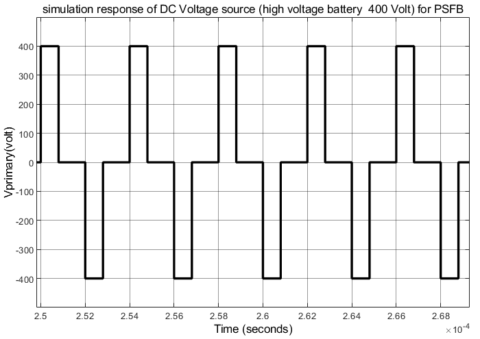
Figure 14. Simulation results of squre wave generator (Inverter) for PSFB
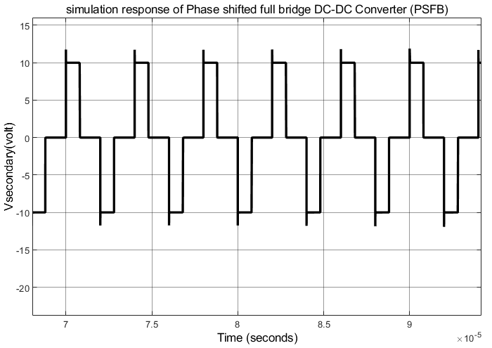
Figure 15. Simulation results of Linear Transformer for PSFB
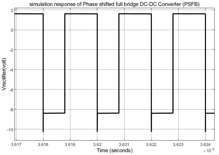
Figure 16. Simulation results of Rectifier for PSFB
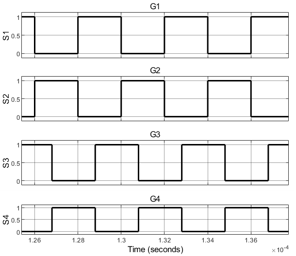
Figure 17. Simulation results of pulses
Figure 18. Simulation results of current
Figure 19. Simulation results of power
| 
|
a. current output | b. voltage output |
|
c. Primary voltage |
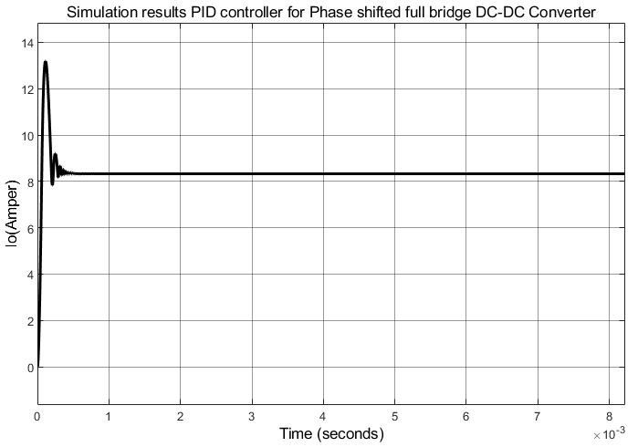
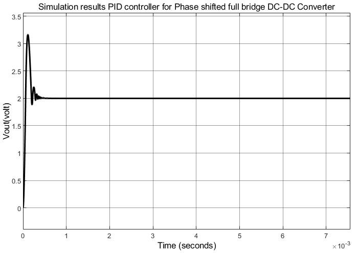
Figure 20. Simulation response for closed-loop of PSFB system using PID controller at = 400,  = 2 volt
| 
|
a. current output | b. voltage output |
|
c. Primary voltage |
Figure 21. Simulation response for closed-loop of PSFB system using PID controller at = 400, = 6 volt
| 
|
a. current output | b. voltage output |
|
c. Primary voltage |
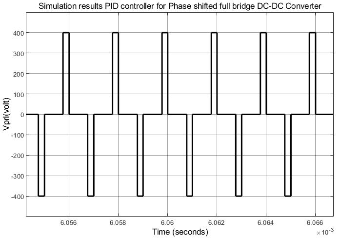
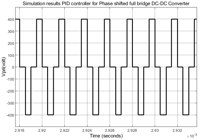
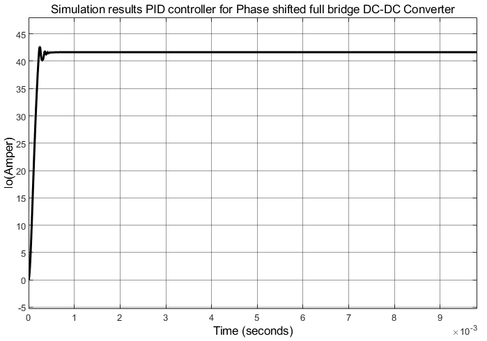
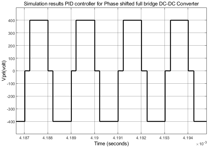
Figure 22. Simulation response for closed-loop of PSFB system using PID controller at = 400, = 10 volt
| 
|
a. current output | b. voltage output |
|
c. Primary voltage |
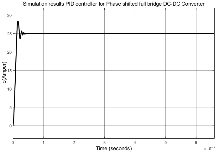
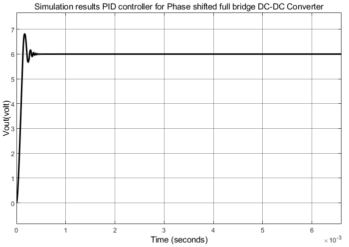
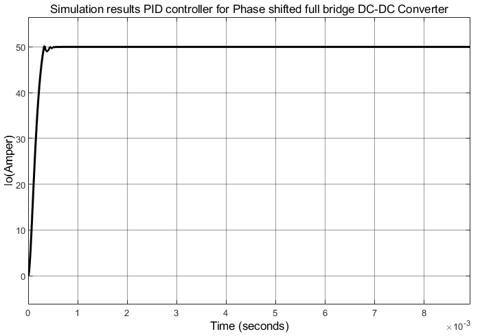
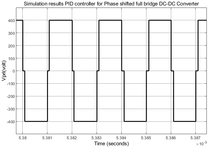
Figure 23. Simulation response for closed-loop of PSFB system using PID controller at = 400, = 12 volt
CONCLUSION
The study presented a single-phase full-wave phase shift converter. Through the study, the system components, operation method, function of each part, control of system input and output, and change of phase shift were identified. Electrical quantities are considered a measure of system performance, therefore, a sensor for these quantities is installed, such as plotting and reading the input and output quantity of each part to identify the behavior, performance, and function of these parts, such as the source voltage, input and output of the inverter, transformer, filter, load voltage and current, etc. The effectiveness of the proposed system was verified, and the system behavior was examined, as well as how to improve the performance and quality of the required output voltage to cover loads under varying operating conditions. From the above, it can be recommended to use it in charging systems for storage units in electrical circuits and systems similar to the system specifications. The current study involves constructing a phase-shifted full bridge (PSFB) converter simulation model. A simulation was conducted, and the main waveforms and shapes were analyzed for each test case. The simulation results included the input and output voltages for each phase. Steady-state and transient states were tested, and identifying the response under constant and variable loads is crucial. The simulation results revealed that the PSFB converter has a good and fast transient response, returning to steady state with minimal overshoot or undershoot. The waveforms and shapes for each phase revealed electrical quantities, including voltage and current, representing the MOSFET signals when zero-voltage switching (ZVS) is required. ZVS is the primary factor for optimizing the converter, increasing efficiency, and reducing losses. The analysis helps evaluate the converter's performance and helps identify suitable practical applications. The used control method significantly improved the response, speed, and accuracy of performance for both the transient and steady-state systems.
REFERENCES
- M. Pástor, D. Gordan, and C. L. Maxwell, “From IGBT to GaN implementation in phase-shifted full-bridge converter,” Electrical Engineering, pp. 1-15, 2025, https://doi.org/10.1007/s00202-025-03125-4.
- P. Roja and V. John, "Asymmetrical Phase-Shifted Full-Bridge Converters in Input-Parallel Output-Parallel Configuration," in IEEE Transactions on Industry Applications, vol. 60, no. 4, pp. 6435-6445, 2024, https://doi.org/10.1109/TIA.2024.3397643.
- L. Xie and X. Yuan, "A High-Performance Phase-Shift Full-Bridge Converter with Rotary Transformer for the Field Excitation of Electric Machines," 2024 International Symposium on Power Electronics, Electrical Drives, Automation and Motion (SPEEDAM), pp. 734-741, 2024, https://doi.org/10.1109/SPEEDAM61530.2024.10609172.
- M. Pástor and D. Gordan, "Phase-Shifted Full-Bridge Converter With High Efficiency," 2024 ELEKTRO (ELEKTRO), pp. 1-6, 2024, https://doi.org/10.1109/ELEKTRO60337.2024.10556882.
- H. Henry, M. R, G. P, C. V, A. G and K. M. B, "Performance Optimization in Phase Shifted Full Bridge Converter Using Parallel Loop Shaping Technique," 2024 IEEE International Conference on Power Electronics, Drives and Energy Systems (PEDES), pp. 1-6, 2024, https://doi.org/10.1109/PEDES61459.2024.10961845.
- S. Ullah, M. U. Hashmi, T. U. Rehman, M. Ali, and A. Manan, “High-Efficiency Battery Charging for Electric Vehicles: MATLAB Simulation of a Phase-Shifted Full-Bridge DC-DC Converter,” Journal of Computing & Biomedical Informatics, vol. 8, no. 01, 2024, https://www.jcbi.org/index.php/Main/article/view/637.
- J. B. Benites Quispe, M. Mezaroba, A. L. Batschauer, and J. M. de Souza Ribeiro, “A Reconfigurable Phase-Shifted Full-Bridge DC–DC Converter with Wide Range Output Voltage,” Energies, vol. 17, no. 14, p. 3483, 2024, https://doi.org/10.3390/en17143483.
- A. Saglam and K. Kayisli, "Design of a Phase Shifted Full Bridge DC-DC ZVS Converter with Analog Control," 2024 Global Energy Conference (GEC), pp. 304-309, 2024, https://doi.org/10.1109/GEC61857.2024.10881567.
- Qin, G., Ma, H., Lei, J., & Hao, C. (2025). Advanced Control Strategies for Enhancing the Performance of Phase-Shifted Full-Bridge Series Resonant DC–DC Converters in Photovoltaic Micro-Inverters. Energies, 18(2), 387, 2025, https://doi.org/10.3390/en18020387.
- O. López-Santos, D. A. Zambrano-Prada, H. Valderrama-Blavi, F. Flores-Bahamonde, C. A. T. Pinzón and L. Martínez-Salamero, "Experimental Efficiency Comparison Between the LLC Resonant Converter and the Phase Shifted Full Bridge Converter Operating as Battery Chargers," IECON 2024 - 50th Annual Conference of the IEEE Industrial Electronics Society, pp. 1-6, 2024, https://doi.org/10.1109/IECON55916.2024.10905314.
- L. Maheshwari et al., "Efficient High-Frequency GaN-Based Phase Shifted Full Bridge Zero-Voltage Switching Converter for Electric Vehicle Auxiliary Power Modules," 2024 IEEE Workshop on Control and Modeling for Power Electronics (COMPEL), pp. 1-6, 2024, https://doi.org/10.1109/COMPEL57542.2024.10614037.
- K. Tokuyasu, K. Kajiwara, Y. Furukawa, H. Fukumori and F. Kurokawa, "Design of Phase-Shifted Full-Bridge DC-DC Converter for Micro EV," 2024 13th International Conference on Renewable Energy Research and Applications (ICRERA), pp. 714-719, 2024, https://doi.org/10.1109/ICRERA62673.2024.10815462.
- E. Aydar and A. F. Bakan, "600W/28V Phase Shifted Full Bridge DC-DC Converter Design," 2024 15th National Conference on Electrical and Electronics Engineering (ELECO), pp. 1-5, 2024, https://doi.org/10.1109/ELECO64362.2024.10847246.
- C. M. Bandeira, N. I. Medina G., G. M. S. Azevedo, R. C. Neto, L. R. Limongi and M. C. Cavalcanti, "Analysis of the Phase-Shift Full-Bridge Converter in 400V and 800V DC Fast Charging Stations," 2023 IEEE 8th Southern Power Electronics Conference and 17th Brazilian Power Electronics Conference (SPEC/COBEP), Florianopolis, Brazil, 2023, pp. 1-8, 2023, https://doi.org/10.1109/SPEC56436.2023.10408584.
- H. Prasad, R. Gupta and N. Yalla, "EV Battery Charging Using High-Frequency PSFB Converter with PFC," 2024 IEEE 4th International Conference on Sustainable Energy and Future Electric Transportation (SEFET), pp. 1-6, 2024, https://doi.org/10.1109/SEFET61574.2024.10718267.
- J. S. Saputro, H. Maghfiroh, F. Adriyanto, M. R. Darmawan, M. H. Ibrahim, and S. Pramono, “Energy Monitoring and control of automatic transfer switch between grid and solar panel for home system,” International Journal of Robotics and Control Systems, vol. 3, no. 1, pp. 59-73, 2023, https://doi.org/10.31763/ijrcs.v3i1.843.
- T. Kareem, S. W. Shneen, and M. Al-Abbasi, “Design and Implementation of Proportional-Integral Controller for Single Phase Stand-Alone Inverter with an LC-Filter,” International Journal of Robotics and Control Systems, vol. 5, no. 2, pp. 1498-1518, 2025, https://doi.org/10.31763/ijrcs.v5i2.1876.
- C. Nagarajan, K. Umadevi, S. Saravanan, and M. Muruganandam, “Performance Analysis of PSO DFFP Based DC-DC Converter with Non Isolated CI using PV Panel,” International Journal of Robotics & Control Systems, vol. 2, no. 2, 2022, https://doi.org/10.31763/ijrcs.v2i2.628.
- S. W. Shneen, H. S. Dakheel, and Z. B. Abdulla, “Advanced Optimal for PV system coupled with PMSM,” Indonesian Journal of Electrical Engineering and Computer Science, vol. 1, no. 3, pp. 556-565, 2016, https://doi.org/10.11591/ijeecs.v1.i3.pp556-565.
- L. K. Fong, M. S. Islam, and M. A. Ahmad, “Optimized PID Controller of DC-DC Buck Converter based on Archimedes Optimization Algorithm,” International Journal of Robotics & Control Systems, vol. 3, no. 4, 2023, https://doi.org/10.31763/ijrcs.v3i4.1113.
- R. K. Gaber, S. W. Shneen, and S. M. Jiaad, “Study and Analysis of PWM with DC-DC Converter for Inverting Buck-Boost Inverter Topology,” International Journal of Robotics and Control Systems, vol. 5, no. 2, pp. 1029-1050, 2025, https://doi.org/10.31763/ijrcs.v5i2.1823.
- S. Chothe, R. T. Ugale and A. Gambhir, "Design and modeling of Phase Shifted Full Bridge DC-DC Converter with ZVS," 2021 National Power Electronics Conference (NPEC), pp. 01-06, 2021, https://doi.org/10.1109/NPEC52100.2021.9672529.
- S. W. Shneen, “Advanced optimal for power-electronic systems for the grid integration of energy sources,” Indonesian Journal of Electrical Engineering and Computer Science, vol. 1, no. 3, pp. 543-555, 2016, https://doi.org/10.11591/ijeecs.v1.i3.pp543-555.
- B. N. Alajmi, N. A. Ahmed, I. Abdelsalam and M. I. Marei, "Phase Shift Full Bridge DC–DC Converter With Active Clamping Circuit for Fuel Cell Electric Vehicles," in IEEE Access, vol. 13, pp. 90875-90895, 2025, https://doi.org/10.1109/ACCESS.2025.3571942.
- C. Nagarajan, B. Tharani, S. Saravanan, and R. Prakash, “Performance estimation and control analysis of AC-DC/DC-DC hybrid multi-port intelligent controllers based power flow optimizing using STEM strategy and RPFC technique,” International Journal of Robotics and Control Systems, vol. 2, no. 1, pp. 124-139, 2022, https://doi.org/10.31763/ijrcs.v2i1.562.
- S. W. Shneen, M. A. A. Hussein, J. A. Kadhum, and S. M. Ali, “Application of LFAC {16 2/3Hz} for electrical power transmission system: a comparative simulation study,” TELKOMNIKA (Telecommunication Computing Electronics and Control), vol. 17, no. 2, pp. 1055-1064, 2019, https://doi.org/10.12928/telkomnika.v17i2.10353.
- O. Diouri, A. Gaga, S. Senhaji, and M. O. Jamil, “Design and PIL test of high performance MPPT controller based on P&O-backstepping applied to DC-DC converter,” Journal of Robotics and Control (JRC), vol. 3, no. 4, pp. 431-438, 2022, https://doi.org/10.18196/jrc.v3i4.15184.
- Z. A. Al-Dabbagh, and S. W. Shneen, “Design of a PID Speed Controller for BLDC Motor with Cascaded Boost Converter for High-Efficiency Industrial Applications,” International Journal of Robotics & Control Systems, vol. 5, no. 1, 2025, https://doi.org/10.31763/ijrcs.v5i1.1601.
- A. A. Rizi, A. Rezaei, M. G. Rizi, and M. A. Rizi, “Design a new multiport DC-DC converter to charge an electric car,” International Journal of Robotics and Control Systems, vol. 2, no. 1, pp. 87-96, 2022, https://doi.org/10.31763/ijrcs.v2i1.566.
- S. W. Shneen, A. L. Shuraiji, and K. R. Hameed, “Simulation model of proportional integral controller-PWM DC-DC power converter for DC motor using matlab,” Indonesian Journal of Electrical Engineering and Computer Science, vol. 29, no. 2, pp. 725-734, 2023, https://doi.org/10.11591/ijeecs.v29.i2.pp725-734.
- G. Qin, H. Ma, J. Lei, and C. Hao, “Advanced Control Strategies for Enhancing the Performance of Phase-Shifted Full-Bridge Series Resonant DC–DC Converters in Photovoltaic Micro-Inverters,” Energies, vol. 18, no. 2, p. 387, 2025, https://doi.org/10.3390/en18020387.
- R. T. Ahmedhamdi and S. W. Shneen, “Using position control to improve the efficiency of wind turbine,” TELKOMNIKA (Telecommunication Computing Electronics and Control), vol. 18, no. 6, pp. 3240-3246, 2020, https://doi.org/10.12928/telkomnika.
- A. Awasthy, S. Singh and S. Rajaram, "Design and Implementation of a Phase Shifted Full Bridge Converter with Cascaded Feedforwarded Control for an Electric Vehicle," 2023 IEEE Renewable Energy and Sustainable E-Mobility Conference (RESEM), pp. 1-5, 2023, https://doi.org/10.1109/RESEM57584.2023.10236298.
- B. A. Avdeev et al., “Overvoltage and Oscillation Analysis for a Full-Bridge Isolated DC-DC Converter,” Journal of Robotics and Control (JRC), vol. 5, no. 6, pp. 1764-1771, 2024, https://doi.org/10.18196/jrc.v5i6.23120.
- S. W. Shneen, and G. A. Aziz, “Simulation model of 3-phase PWM rectifier by using MATLAB/Simulink,” International Journal of Electrical and Computer Engineering, vol. 11, no. 5, p. 3736, 2021, https://doi.org/10.11591/ijece.v11i5.pp3736-3746.
- L. H. Abood, “Optimal modified PID controller for automatic voltage regulation system,” In AIP Conference Proceedings, vol. 2415, no. 1, p. 030007, 2022, https://doi.org/10.1063/5.0092583.
- S. Yalçın, T. Göksu, S. Kesler, and O. Bingöl, “Experimental analysis of phase shift modulation methods effects on EMI in dual active bridge DC-DC converter,” Engineering Science and Technology, an International Journal, vol. 43, p. 101435, 2023, https://doi.org/10.1016/j.jestch.2023.101435.
- A. A. Mutlag and S. W. Shneen, “A Comparative Investigation of Hybrid MPPT Methods for Enhancing Solar Power Generation in Renewable Energy Systems,” International Journal of Electrical and Electronics Research, vol. 12, no. 3, pp. 991-1000, 2024, https://doi.org/10.37391/ijeer.120333.
- W. Phetphimoon, K. Bhumkittipich, P. Prabpal, P. Yupapin, and Y. Kongjeen, “Phase‐Shifted Full‐Bridge ZVS DC‐DC Converter with Synchronous Double Rectifiers for Battery Charging Applications,” International Transactions on Electrical Energy Systems, vol. 2022, no. 1, p. 4813528, 2022, https://doi.org/10.1155/2022/4813528.
- A. A. Mutlag, M. K. Abd, and S. W. Shneen, “Power Management and Voltage Regulation in DC Microgrid with Solar Panels and Battery Storage System,” Journal of Robotics and Control (JRC), vol. 5, no. 2, pp. 397-407, 2024, https://doi.org/10.18196/jrc.v5i2.20581.
- F. R. Yaseen and H. Al-Khazraji, “Optimized Vector Control Using Swarm Bipolar Algorithm for Five-Level PWM Inverter-Fed Three-Phase Induction Motor,” International Journal of Robotics & Control Systems, vol. 5, no. 1, 2025, https://doi.org/10.31763/ijrcs.v5i1.1713.
- M. H. Cao, Z. L. Nie, S. Ai, and J. Xu, “Efficiency Optimization of the active auxiliary network in the phase-shifted full-bridge DC/DC converter,” Journal of Electrical Engineering & Technology, vol. 19, no. 3, pp. 1531-1539, 2024, https://doi.org/10.1007/s42835-023-01658-x.
- S. W. Shneen and A. L. Shuraiji, “Simulation model for pulse width modulation-voltage source inverter of three-phase induction motor,” International Journal of Power Electronics and Drive Systems, vol. 14, no. 2, pp. 719-726, 2023, https://doi.org/10.11591/ijpeds.v14.i2.pp719-726.
- S. L. Mekonnen et al., "Research on Phase-Shifted Full-Bridge ZVS DC-DC Converter with Multi-pulsed Load," 2024 IEEE 10th International Power Electronics and Motion Control Conference (IPEMC2024-ECCE Asia), pp. 4385-4390, 2024, https://doi.org/10.1109/IPEMC-ECCEAsia60879.2024.10567725.
- S. W. Shneen, H. S. Dakheel, and Z. B. Abdulla, “Design and implementation of variable and constant load for induction motor,” International Journal of Power Electronics and Drive Systems, vol. 11, no. 2, p. 762, 2020, https://doi.org/10.11591/ijpeds.v11.i2.pp762-773.
- M. N. Huynh, H. N. Duong, and V. H. Nguyen, “A passivity-based control combined with sliding mode control for a DC-DC boost power converter,” Journal of Robotics and Control (JRC), vol. 4, no. 6, pp. 780-790, 2023, https://doi.org/10.18196/jrc.v4i6.20071.
- Z. A. Al-Dabbagh, and S. W. Shneen, “Neuro-Fuzzy Controller for a Non-Linear Power Electronic DC-DC Boost Converters,” Journal of Robotics and Control (JRC), vol. 5, no. 5, pp. 1479-1491, 2024, https://doi.org/10.18196/jrc.v5i5.22690.
- A. Kulkarni, H. R. Bhawane, P. Chaturvedi and S. Kamble, "Optimized Dual Phase Shift Control for Dual Active Bridge DC-DC Converter," 2024 IEEE International Conference on Power Electronics, Drives and Energy Systems (PEDES), Mangalore, India, 2024, pp. 1-6, 2024, https://doi.org/10.1109/PEDES61459.2024.10961877.
- S. W. Shneen, Z. B. Abdullah, and H. S. Dakheel, “Design and Implementation of Voltage Source Inverter Using Sinusoidal Pulse Width Modulation Technique to Drive a Single-Phase Induction Motor,” International Journal of Robotics and Control Systems, vol. 4, no. 4, pp. 1527-1546, 2024, https://doi.org/10.31763/ijrcs.v4i3.1541.
- A. Mansouri, R. Gavagsaz-Ghoachani, M. Phattanasak, and S. Pierfederici, “Nonlinear cascaded control for a dc-dc boost converter,’ Journal of Robotics and Control (JRC), vol. 4, no. 4, pp. 521-536, 2023, https://doi.org/10.18196/jrc.v4i4.18932.
- S. W. Shneen, F. N. Abdullah, and D. H. Shaker, “Simulation model of single phase PWM inverter by using MATLAB/Simulink,” International Journal of Power Electronics and Drive Systems, vol. 12, no. 1, p. 212, 2021, https://doi.org/10.11591/ijpeds.v12.i1.pp212-216.
- N. N. Kadhim, L. H. Abood, and Y. Abd Mohammed, “Design an optimal fractional order PID controller for speed control of electric vehicle,” Journal Européen des Systèmes Automatisés, vol. 56, no. 5, p. 735, 2023, https://doi.org/10.18280/jesa.560503.
- N. F. Diana, W. M. Utomo, A. B. A. Bakar, S. Salimin, G. Priyandoko, and W. Widjonarko, “Voltage Tracking of Bidirectional DC-DC Converter Using Online Neural Network for Green Energy Application,” Journal of Robotics and Control (JRC), vol. 6, no. 1, pp. 1-11, 2025, https://doi.org/10.18196/jrc.v6i1.22326.
- S. W. Shneen, R. T. Ahmedhamdi, and M. K. Al-Ghezi, “A-review of Simulink for single-phase rectifier,” Int J Adv Appl Sci ISSN, vol. 2252, no. 8814, p. 8814, 2022, https://doi.org/10.11591/ijaas.v11.i1.pp76-87.
- S. Goudarzitaemeh and M. Pahlevani, "Extended Phase Shift Control of a Novel Bidirectional DC–DC Converter With Direct Power Transfer," in IEEE Journal of Emerging and Selected Topics in Power Electronics, vol. 12, no. 5, pp. 4521-4537, 2024, https://doi.org/10.1109/JESTPE.2024.3439098.
- S. W. Shneen, “Advanced optimal for three phase rectifier in power-electronic systems,” Indonesian Journal of Electrical Engineering and Computer Science, vol. 11, no. 3, pp. 821-830, 2018, https://doi.org/10.11591/ijeecs.v11.i3.pp821-830.
- P. L. Métayer, Q. Loeuillet, F. Wallart, C. Buttay, D. Dujic and P. Dworakowski, "Phase-Shifted Full Bridge DC–DC Converter for Photovoltaic MVDC Power Collection Networks," in IEEE Access, vol. 11, pp. 19039-19048, 2023, https://doi.org/10.1109/ACCESS.2023.3247952.
- S. W. Shneen, C. Mao, and D. Wang, “Advanced optimal PSO, Fuzzy and PI controller with PMSM and WTGS at 5Hz side of generation and 50Hz Side of Grid,” International Journal of Power Electronics and Drive Systems, vol. 7, no. 1, p. 173, 2016, https://doi.org/10.11591/ijpeds.v7.i1.pp173-192.
- P. E. Poudyal, V. Vigneshwar, N. K. Kumar, V. Indragandhi, and A. N. Ali, “Design and simulation of Phase shifted DC-DC full bridge converter,” In IOP Conference Series: Materials Science and Engineering, vol. 623, no. 1, p. 012021, 2019, https://doi.org/10.1088/1757-899X/623/1/012021.
- D. H. Shaker, S. W. Shneen, F. N. Abdullah, and G. A. Aziz, “Simulation Model of Single-Phase AC-AC Converter by Using MATLAB,” Journal of Robotics and Control (JRC), vol. 3, no. 5, pp. 656-665, 2022, https://doi.org/10.18196/jrc.v3i5.15213.
AUTHOR BIOGRAPHY

| Luay G. Ibrahim was born in Baghdad, Iraq in April of 1977. He received his B.Sc., M.Sc. and Ph.D. degrees from the Department of Electrical Engineering, University of Technology (UOT), Iraq, in 2003, 2006, and 2020 respectively. In 2006, he joined the department of electrical engineering at the University of Technology, Baghdad, in Iraq, as an Assistant Lecturer. Currently, he is a lecturer in the College of Electrical Engineering department of electrical engineering at UOT. His major research interest includes covers a wide range of subjects in power system stability FACTS devices, power system analysis and digital simulation, power system operation and control, and electrical machine design. |
|
|

| Salam Waley Shneen     Educational Background: July 2016 PhD, Degree in Electrical Engineering-Power Electronic, School of Electrical and Electronic Engineering, Huazhong University of Science and Technology (HUST). Nov 2005 MSc, Degree in Engineering Educational Technology-Electrical Engineering, Technical Education Department, University of Technology, Iraq-Baghdad. July 1998 BSc, Degree in Electrical Engineering and Education, Technical Education Department, University of Technology, Iraq- Baghdad. Oct 1994 Diploma in Electrical Technology, Technical Instructors Training Institute, Iraq Baghdad. 1992 High School Bakaloria Degree Preparatory Technical School (Electrical Section), Almashtal Technical Secondary School Iraq-Baghdad. Work Experience 1998-2005 Engineer in: Electronic Lab., Digital Electronic Lab., Communication Lap., Fundamental of Electric Engineering Lab. Cad Lab. In Technical Education Department, University of Technology, Iraq-Baghdad. 2005-2016 Assistant Lecturer in: Electronic Lab. Lecturer Advanced Electronic, Lecturer Fundamental of Electric Engineering, Technical Education Department, Electromechanical Department University of Technology, Iraq-Baghdad. 2016- 2017 Lecturer in: Electronic Lab. Fundamental of Electric Engineering Lab., Lecturer Electronic Circuits, Lecturer Fundamental of Electric Engineering with Electrical and Electronic Circuits Electromechanical Department University of Technology, Iraq-Baghdad. 2017-- today Lecturer in: Energy and Renewable Energies Technology Center, University of Technology, Iraq-Baghdad. He can be contacted at email: salam.w.shneen@uotechnology.edu.iq or salam_waley73@yahoo.com. Educational Background: July 2016 PhD, Degree in Electrical Engineering-Power Electronic, School of Electrical and Electronic Engineering, Huazhong University of Science and Technology (HUST). Nov 2005 MSc, Degree in Engineering Educational Technology-Electrical Engineering, Technical Education Department, University of Technology, Iraq-Baghdad. July 1998 BSc, Degree in Electrical Engineering and Education, Technical Education Department, University of Technology, Iraq- Baghdad. Oct 1994 Diploma in Electrical Technology, Technical Instructors Training Institute, Iraq Baghdad. 1992 High School Bakaloria Degree Preparatory Technical School (Electrical Section), Almashtal Technical Secondary School Iraq-Baghdad. Work Experience 1998-2005 Engineer in: Electronic Lab., Digital Electronic Lab., Communication Lap., Fundamental of Electric Engineering Lab. Cad Lab. In Technical Education Department, University of Technology, Iraq-Baghdad. 2005-2016 Assistant Lecturer in: Electronic Lab. Lecturer Advanced Electronic, Lecturer Fundamental of Electric Engineering, Technical Education Department, Electromechanical Department University of Technology, Iraq-Baghdad. 2016- 2017 Lecturer in: Electronic Lab. Fundamental of Electric Engineering Lab., Lecturer Electronic Circuits, Lecturer Fundamental of Electric Engineering with Electrical and Electronic Circuits Electromechanical Department University of Technology, Iraq-Baghdad. 2017-- today Lecturer in: Energy and Renewable Energies Technology Center, University of Technology, Iraq-Baghdad. He can be contacted at email: salam.w.shneen@uotechnology.edu.iq or salam_waley73@yahoo.com. |
Luay G. Ibrahim (Design and Implementation of PID Controller for Phase Shifted Full Bridge DC-DC Converter)