ISSN: 2685-9572 Buletin Ilmiah Sarjana Teknik Elektro
Vol. 7, No. 4, December 2025, pp. 875-890
Adaptive FLC-based Shunt Active Power Filter with a PV-Fed DC Link for Improved Current Compensation and THD Mitigation
SH Suresh Kumar Budi 1, R Kiranmayi 2
1 Assistant Professor, CMR Technical Campus, Kandlakoya, Medchal, Hyderabad, Telangana 501401, India
2 Professor of EEE Dept., Jawaharlal Nehru Technological University (JNTU) Anantapur, Ananthapuramu,
Andhra Pradesh, India
ARTICLE INFORMATION |
| ABSTRACT |
Article History: Received 27 June 2025 Revised 08 August 2025 Accepted 24 November 2025 |
| 
Power quality improvement with traditional controllers (PI, PID, fixed-parameter FLC) is difficult when dealing with nonlinear, time-varying loads and dynamic grid conditions. For microgrids that incorporate renewable energy sources, it is challenging to acquire the precise mathematical models that are necessary for this work. To address power quality challenges, such as distortion of current and Total Harmonic Distortion (THD), produced by nonlinear loads in PV fed systems, such as solar energy conversion, this publication proposes an Adaptive Fuzzy Logic Controller (FLC) based shunt Active Power Filter (APF). An analysis of the power quality enhancement achieved in a distribution power system using a single-stage solar PV integrated shunt APF is presented in this paper. In order to improve load side parameters, such as the elimination of even and odd current harmonics utilizing shunt APF is employed. This filter makes use of a shared DC-link voltage source. In addition, it transfers energy from the PV system's solar panels to the DC link voltage, which is an extra effort. In this paper, It looks at a single-phase inverter that uses an Adaptive FLC to improve parameters on the source and load sides, as well as harmonics, in grid-connected Distributed Generation systems. Also included is a detailed description of the active power filter's chosen current reference generator. Results that have been validated are attained using MATLAB/SIMULINK(R2023b). |
Keywords: Shunt APF; Power Quality; Total Hormonic Distortion; PV System; Adaptive FLC |
Corresponding Author: SH Suresh Kumar Budi, Assistant Professor, CMR Technical Campus, Kandlakoya, Medchal, Telangana, India, 501401. Email: bsrihari99@gmail.com |
This work is open access under a Creative Commons Attribution-Share Alike 4.0 
|
Document Citation: SH S. K. Budi and R Kiranmayi, “Adaptive FLC-based Shunt Active Power Filter with a PV-Fed DC Link for Improved Current Compensation and THD Mitigation,” Buletin Ilmiah Sarjana Teknik Elektro, vol. 7, no. 4, pp. 875-890, 2025, DOI: 10.12928/biste.v7i4.13804. |
INTRODUCTION
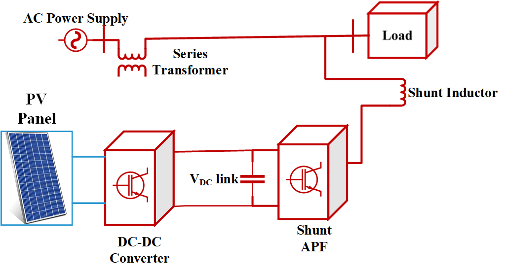
When it comes to power sources, electrical energy has recently surpassed all others. Having access to power is fundamental to daily life. The dependability and regularity of the electricity supplied to the end user's apparatus are also critical to its efficient operation. A constant, high-quality power supply is commonly required by commercial and industrial loads [1]-[4]. That is why protecting the stability of the power grid must be an urgent concern. The nonlinear components have a significant impact on the power supply's efficiency and reliability [5]-[7]. Electronic equipment can lead to a range of power quality issues. Unreliable power might be caused by fluctuations in voltage that occur as a result of things like lightning strikes, network outages, or the switching of capacitor banks [8]-[12]. Overuse of rectifiers, laser printers, and computers results in reactive and harmonic power [12]-[14]. Immediate action is required to resolve this type of issue before it worsens. Despite their size, resonance issues, and the impact of the source impedance on performance, passive filters have traditionally been employed for reactive power disturbances and harmonic production. The energy supply can be made better with the help of active power filters [15]. In this paper, the shunt APF is controlled by the current in the d-q axes of the load current, and an adaptive FLC maintains the voltage at the Solar Fed DC-interface in Figure 1 [16]. Various load currents and variable voltage scenarios are covered in this work, along with the static and dynamic behavior of control circuits. With static and dynamic nonlinear loads, the Shunt APF is used to decrease fluctuations and harmonics, among other things, and an adaptable FLC is constructed for the plant as its parameters change. Power quality improvement with traditional controllers (PI, PID, fixed-parameter FLC) is difficult when dealing with nonlinear, time-varying loads and dynamic grid conditions. For microgrids that incorporate renewable energy sources, it is challenging to acquire the precise mathematical models that are necessary for these work [18]. Despite not requiring a model, the performance of fixed-rule FLCs degrades as a result of drifting system parameters, and they do not have an automatic adaptation mechanism. Instead, then focusing on both steady-state and transient performance, most current systems only handle one [17].
Figure 1. Block diagram of Solar Fed Shunt Active Power Filter
METHODOLOGY MATHEMATICAL MODELLING AND SYSTEM CONFIGURATION
Shunt APF
Figure 2 presents a block design of the shunt converter. Rectify reactive power and eliminate current harmonics via shunt converters. Shunt Converters supply or absorb power for the DC-Link Capacitor's series converter. A Shunt Converter converts DC-Link-Power-Demand from Series-Converters to AC to enable their operation [43]-[48]. Shunt converters adjust load power consumption via shunt inductance. The  theory uses Clark's Transformation to convert electrical variables from a-b-c coordinates to
  dimensions. Electrical values are given in coordinates using (1) and (2).
| 
| (1) |
| 
| (2) |
From (3) and (4), one can calculate the real and reactive power by considering the current and voltage at any point in the coordinates .
| 
| (3) |
| 
| (4) |
Similar to the Synchronous Reference Frame Theory, the theory comprises a standard component and an oscillatory factor pertaining to actual and reactive power, as delineated in (5) and (6).
| 
| (5) |
| 
| (6) |
The reference current that is created can be transformed from coordinates to  coordinates using (7).
| 
| (7) |
The shunt converter must sustain a stable DC connection voltage. The variation in real and reactive power control is determined by the phase angle δ. Reference signals can be generated and transmitted to the PWM generator through contrasting the reference current with the load current. The shunt voltage source converter obtains its gating pulses from the PWM generator.
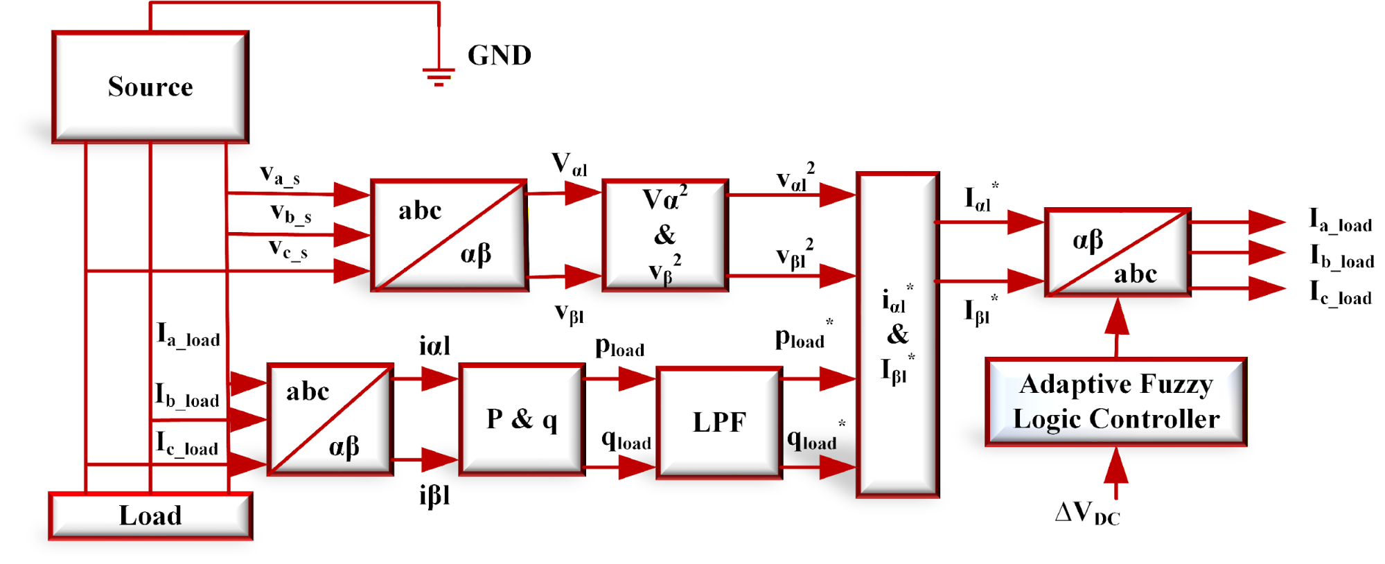
Figure 2. Shunt-APF Configuration
Solar PV System
A PV array is constructed using PV solar cells connected in series and parallel, as shown in Figure 3 for a basic equivalent circuit model. Load current and solar irradiation intensity are the primary determinants of photocurrent, which in turn determines the voltage output of a photovoltaic cell [22]. The series circuit that controls the power output of a solar cell includes a diode, a network of resistors, and an ILGC, as shown in Figure 3 [23][24].
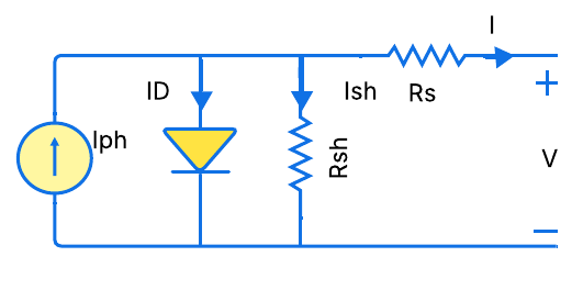
Figure 3. Block diagram of PV cell
Mathematical modelling of solar cell in MATLAB,  is the output current of PV cell,
  is the output voltage of PV cell,
  is the photo generated current,
  is the Diode Current,
  is the Shunt Current,
  is the Open circuit voltage,
  is the Diode revesre saturation current (
 ),
),  is the Cell Saturation current at
  ,
,  is the Short circuit current,
  is the Diode Voltage,
  ,
,  is the Series and shunt resistances, respectively, is the Current due to shunt resistance
  is the Elementary charge
  ,
,  is the Boltzmann Constant
  J/K,
J/K,  is the Idealist Factor,
  is the Cell temperature,
  is the Reference temperature,
  is the Short circuit current temperature coefficient at ,
  is the number of solar cells in the series in the solar module,
  is the number of solar cells in parallel in the solar module. Applying Kirchhoff’s current law in the model shown in Figure 3,
The current divided through diode is
| 
| (15) |
Where is the diode saturation current,  is the diode quality factor,
  is the absolute temperature of cell ().
| 
| (16) |
Maximum output of PV panel is as given below. The current at maximum power point  is
is
| 
| (17) |
is the maximum panel current,  is the maximum panel voltage,
  is the maximum power point by PV panel.
| 
| (18) |
The  of panel is given as
| 
| (11) |
| 
| (12) |
The “Photovoltaic generator (PVG)” or “PV array” is composed of many PV Panels connected in  modules in series,
  modules in Parallel panels to indulge desired values of voltage and current.
| 
| (19) |
| 
| (20) |
Where  and
and  are generated output voltage, current at PV array module. Then we have to compute PVarray voltage and current which are
  ,
,  and
and  .
.
Where,
Solar panels automatically incorporate bypass diodes to regulate the amount of voltage that goes above what is needed. However, the system's price tag will increase as a result of this [19].
CONTROL METHOD
When dealing with power quality challenges, adaptive fuzzy logic controllers (FLC) are typically preferred over traditional controllers due to their superior ability to manage nonlinear, time-varying, and unpredictable system dynamics. If the system parameters are unpredictable or difficult to model, FLC can be used because it does not require an exact mathematical model but instead operates on linguistic norms [35]. The ability to adjust membership functions and rules in real time allows adaptive FLC to be more flexible and keep performance constant regardless of changes in load or supply. Superior to fixed-parameter PI/PID controllers in handling harmonics, voltage sags/swells, and other unforeseen disturbances; robust to disturbances. Speedier dynamic response-Improves power quality in transient settings by rapidly adjusting control actions without excessive overshoot or steady-state error [36]. For complicated and changeable power quality problems, adaptive fuzzy logic controllers (FLCs) are better than traditional, inflexible controllers because they mix fuzzy logic with real-time self-tuning.
The error (Vdcref - Vdc) and the change in error serve as the sources for the FLC, which are inputs to the FLC controller. The FLC is constantly evaluating and computing the inputs, and fuzzy logic rules are used to optimize the performance of the PI controller parameters on the fly [37]-[42]. Figure 4 displays the Adaptive FLC control diagram. Adaptive FLC inputs might meet PI self-calibration requirements for error, change in error, and output at different intervals. Figure 5 shows the input variables' membership functions, whereas Figure 6 shows the same thing for the output variables. The integral gain membership function is shown in Figure 7, while the proportional gain  membership function is shown in Figure 8. Figure 8 shows the control strategy flow diagram that was suggested [25][26].
The implementation process of an adaptive controller includes performance input. By assigning recognitions or recompenses to particular control actions that improve present performance, the index gives finest states for constructing the best constraint states through Fuzzy Interface System. If you want your output control signal to work as well as possible, you need to get rid of power loss caused by things like harmonics, voltage distortion, current distortion, and similar issues [27]-[31]. The membership functions (MFs) for all fuzzy variables are negative big (NB), negative medium (NM), negative small (NS), zero (ZE), positive small (PS), positive medium (PM), positive big (PB). To apply the same MFs for these variables as in the previous way, it can expand the FLC's inference table to include the source and load voltages and currents. An FLC rule table is shown in Table 1.
To reduce harmonics in the load current, an Adaptive FLC based on an APF is used. It is possible to approximate the orientation currents by regulating the DC link voltage. The voltage at the point of addition has a reference value. The current state of the error signal monitoring is ensured by FLC, which controls the signal so that the error is always zero. To maintain a constant DC interface voltage, the current regulator adjusts this little active current in response to feedback from the FLC. Figure 4 shows the schematic of the an Adaptive FLC based Shunt APF control system [32]-[36]. To some degree, the projected Adaptive FLC approach reduces effect of outside conflicts and errors. Targeting nonlinear systems with few known or uncertain parameters and disturbances, it combines fuzzy framework qualities with adaptive control tactics, critique linearization methods, and optimum control theory to solve trajectory control problems.
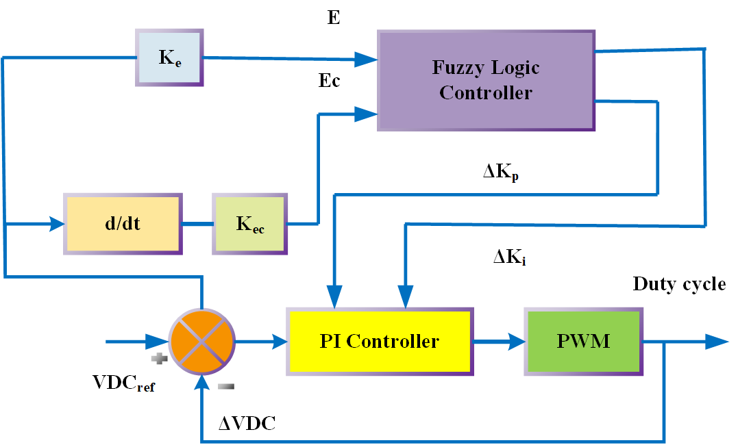
Figure 4. Control block diagram for Adaptive Fuzzy Logic Controller
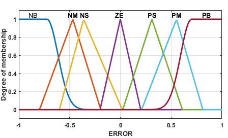
Figure 5. Error MFs
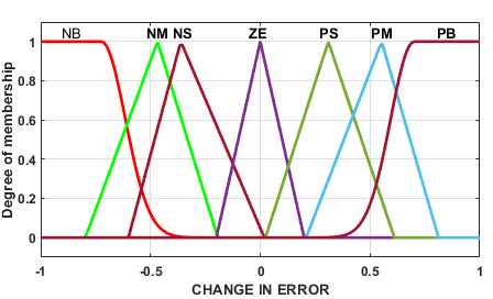
Figure 6. Change in Error MFs
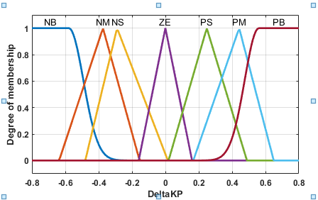
Figure 7.  MFs
MFs
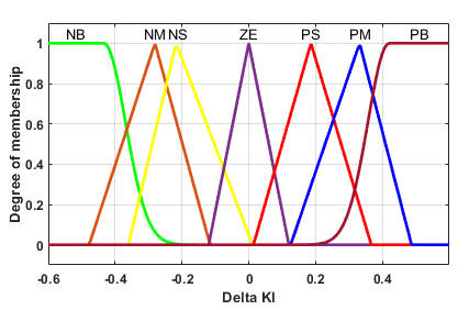
Figure 8.  MFs
MFs
Table 1. Rule table for FLC
Rule Table | Change of Error ( ) ) |
NB | NM | NS | ZE | PS | PM | PB |
Error (e) | NB | NB | NB | NB | NB | NM | NS | ZE |
NM | NB | NB | NB | NM | NS | ZE | PS |
NS | NB | NB | NM | NS | ZE | PS | PM |
ZE | NB | NM | NS | ZE | PS | PM | PB |
PS | NM | NS | ZE | PS | PM | PB | PB |
PM | NS | ZE | PS | PM | PB | PB | PB |
PB | ZE | PS | PM | PB | PB | PB | PB |
RESULT AND DISCUSSION
Figure 9 and Figure 10 Current Compensation with FLC and Adaptive FLC, respectively. The suggested adaptive controller stabilizes the source current, resulting in a sinusoidal waveform and minimized fluctuations. The simulation results for  and
and  during distortion after the deployment of Adaptive FLC are presented in Figure 11 and Figure 12. Figure 11 illustrates the Source Voltage and Source Current with Adaptive FLC, while Figure 12 illustrates the Voltage Source and Current Source with FLC. It examines the Adaptive FLC, which maintains a steady source voltage magnitude compared to FLC, while also reducing source current distortions. Figure 13 and Figure 14 present the simulation results for
  and
and  during distortion subsequent to the introduction of Adaptive FLC. Figure 13 illustrates the voltage () and current () with fuzzy logic control (FLC), whereas Figure 14 presents the voltage () and current () with Adaptive fuzzy logic control. It examines the Adaptive FLC, which maintains a steady voltage magnitude compared to FLC, while also reducing load current distortions. Figure 15 to Figure 22 illustrate total harmonic distortion (THD) for source and load currents, source and load voltages, respectively.
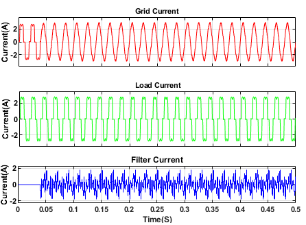
Figure 9. Simulation result Current of Compensation with FLC
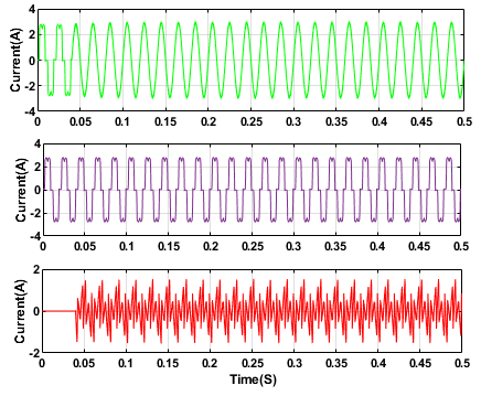
Figure 10. Simulation result of Current Compensation with Adaptive FLC
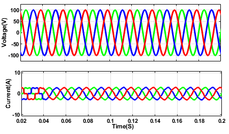
Figure 11. Result of and with Adaptive FLC
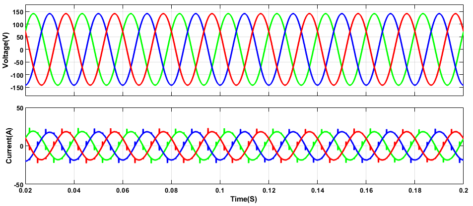
Figure 12. Result of and with FLC
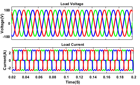
Figure 13. Simulation result of and with FLC
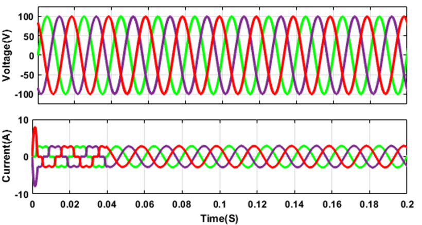
Figure 14. Simulation result of Load Voltage and Load Current with Adaptive FLC
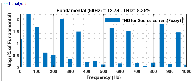
Figure 15. THD for  with FLC
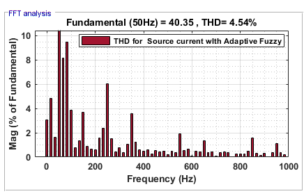
Figure 16. THD for with Adaptive FLC
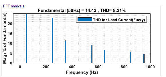
Figure 17. THD for with FLC
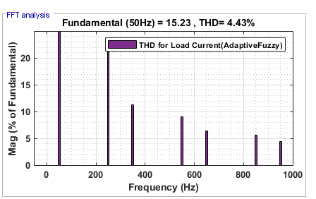
Figure 18. THD for with Adaptive FLC
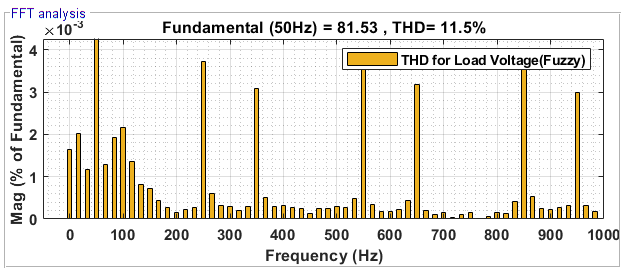
Figure 19. THD for with FLC
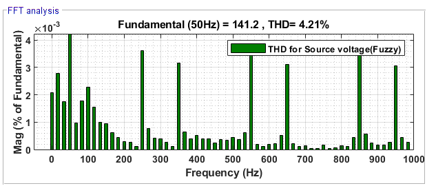
Figure 20. THD for  with FLC
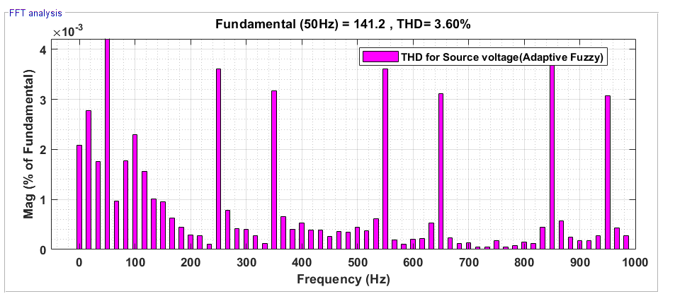
Figure 21. THD for with Adaptive FLC
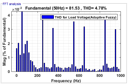
Figure 22. THD for with Adaptive FLC
Table 2. Comparison of THD values
Control Methods | % THD Values |
Source Current | Source Voltage | Load Current | Load Voltage |
PV fed Shunt APF without PI | 18.8% | 14.8% | 24% | 23.4% |
PV fed Shunt APF with PI | 16.6% | 6.1% | 10.3% | 15.1% |
PV fed Shunt APF with FLC | 8.35% | 4.21% | 8.21% | 11.5% |
PV fed Shunt APF with Adaptive FLC | 4.54% | 3.60% | 4.43% | 4.78% |
CONCLUSIONS
Adaptive FLC based Shunt APF is proposed in this Paper to tackle power quality difficulties and VDC-Link regulation, two of the most pressing problems in the power quality industry. The MATLAB/Simulink model is built and the simulation results are evaluated to determine how the shunt APF's two controllers, the FLC and the Adaptive FLC, work. Every controller has its own THD value, which is then compared with the others. Findings demonstrate that 3.60% for source voltage and 4.54 % for source current THD when an Adaptive FLC is employed. One more proof that this controller's compensation for all parameters works. Thus, among the alternatives, the adaptive FLC offers the best performance. Among the many advantages of the proposed controller are the following: Voltage distortion was used to provide steady voltage regulation. There is a considerable improvement in power supply losses and VSI compared to the earlier method. There are a lot of Power Q problems that can be solved by the current approach using Shunt APF
DECLARATION
Author Contribution
All authors contributed equally to the main contributor to this paper. All authors read and approved the final paper.
Funding
This research received no external funding.
Acknowledgement
Write a thank you to those who have helped in this research who are not listed in the author's list.
Conflicts of Interest
No conflict of interest.
REFERENCES
- D. K. Nishad, A. N. Tiwari, S. Khalid, S. Gupta, and A. Shukla, “AI based UPQC control technique for power quality optimization of railway transportation systems,” Sci. Rep., vol. 14, no. 1, p. 17935, 2024, https://doi.org/10.1038/s41598-024-68575-5.
- P. Meenalochini, R. Karthick, and E. Sakthivel, “An efficient control strategy for an extended switched coupled inductor quasi-Z-source inverter for 3 Φ grid connected system,” J. Circuits, Syst. Comput., vol. 32, no. 11, p. 2450011, 2023, https://doi.org/10.1142/S0218126624500117.
- T. Porselvi, P. Rajesh, and F. H. Shajin, “An intelligent approach for cascaded multi-level inverter (CMLI) with grid-connected adaptive system,” Environ. Dev. Sustain., pp. 1–23, 2024, https://doi.org/10.1007/s10668-023-04432-1.
- S. K. Yadav, K. B. Yadav, and A. Priyadarshi, “Performance analysis of three-phase solar PV, BESS, and wind integrated UPQC for power quality improvement,” Comput. Electr. Eng., vol. 116, p. 109230, 2024, https://doi.org/10.1016/j.compeleceng.2024.109230.
- L. B. Chilakapati and T. G. Manohar, “Power quality enhancement in a grid-integrated solar-PV system with an adaptive UPQC control strategy,” Solar Energy Sustain. Dev. J., vol. 13, no. 2, pp. 120–137, 2024, https://doi.org/10.51646/jsesd.v13i2.220.
- A. Y. Qasim, F. R. Tahir, and A. N. B. Alsammak, “Improving power quality in distribution systems using UPQC: An overview,” J. Eur. Syst. Autom., vol. 57, no. 2, 2024, https://doi.org/10.18280/jesa.570201.
- L. Chitra, M. Sridevi, and S. Prakash, “Intelligent MPPT controller for PV with energy storage system fed UPQC system for power quality improvement,” in Proc. 7th Int. Conf. Circuit Power Comput. Technol. (ICCPCT), vol. 1, pp. 1287–1293, 2024, https://doi.org/10.1109/ICCPCT61902.2024.10672830.
- D. Sunitha, M. A. Bhaskar, S. V. Anjana, V. S. Kumar and S. S. Dash, "Power Quality Enhancement with Wind Energy Coupled UPQC with Adaptive Controller," 2019 8th International Conference on Renewable Energy Research and Applications (ICRERA), pp. 898-903, 2019, https://doi.org/10.1109/ICRERA47325.2019.8997101.
- A. Ranjan and J. Choudhary, “Meta-heuristic-based power quality improvement in UPQC-based grid-connected adaptive renewable energy system,” Multimed. Tools Appl., pp. 1–30, 2024, https://doi.org/10.11591/ehs.v2i1.pp14-29.
- C. Shravani and R. L. Narasimham, “UPQC-based power quality improvement in grid-linked PV, battery & wind systems,” in E3S Web Conf., vol. 547, p. 01007, 2024, https://doi.org/10.1051/e3sconf/202454701007.
- M. Pandikumar, K. J. Jenisha, M. Baskar, M. Swathi, N. K. Rayaguru, and S. Baskaran, “Optimized power quality enhancement in PV-integrated UPQC systems using chaotic PSO-based MPPT algorithm,” in Proc. Int. Conf. Advancement Renew. Energy Intell. Syst. (AREIS), pp. 1–6, 2024, https://doi.org/10.1109/AREIS62559.2024.10893654.
- E. Borkar and N. Singh, “Power quality enhancement by PV-UPQC for non-linear load,” in Artif. Intell. Tech. Power Syst. Oper. Anal., pp. 37–64, 2024, https://doi.org/10.1201/9781003301820-3.
- D. Krishna, M. Sasikala, and R. Kiranmayi, “FOPI and FOFL controller based UPQC for mitigation of power quality problems in distribution power system,” Journal of Electrical Engineering & Technology, vol. 17, no. 3, pp. 1543-1554, 2022, https://doi.org/10.1007/s42835-022-00996-6.
- D. Krishna, M. Sasikala, and V. Ganesh, “Adaptive FLC-based UPQC in distribution power systems for power quality problems,” International Journal of Ambient Energy, vol. 43, no. 1, pp. 1719-1729, 2022, https://doi.org/10.1080/01430750.2020.1722232.
- E. Himabindu, D. Krishna, S. Venkateshwarlu, and K. C. Reddy, “Solar PV fed DC link voltage for fuzzy logic sliding mode controller based UPQC to improve the dynamic performance in power grid,” J. Appl. Sci. Eng., vol. 28, no. 5, pp. 969–978, 2025, http://dx.doi.org/10.6180/jase.202505_28(5).0006.
- B. S. Goud, C. N. S. Kalyan, D. Krishna, B. N. Reddy, M. Bajaj, M. F. Ansari, and R. K. Barik, “Novel optimization techniques and controllers for power quality improvement,” in Proc. 1st Int. Conf. Circuits, Power Intell. Syst. (CCPIS), pp. 1–6, 2023, https://doi.org/10.1109/CCPIS59145.2023.10291320.
- L. B. Chilakapati, “Power quality improvement in a grid connected solar-PV system with adaptive neuro-fuzzy controller based UPQC,” Int. Res. J. Multidiscip. Technovation, vol. 7, no. 1, pp. 264–279, 2025, https://doi.org/10.54392/irjmt25118.
- L. Sahihi and B. Berbaoui, “Hybrid neuro-fuzzy integral sliding mode control technique optimized UPQC for power quality improvement in solar systems,” Iran. J. Fuzzy Syst., vol. 22, no. 1, pp. 147–168, 2025, https://doi.org/10.22111/ijfs.2025.49224.8678.
- P. Ray, P. K. Ray, P. S. Puhan, and M. T. K. Liyanage, “Performance improvement of microgrid with strategic control of distributed energy resources integrated UPQC,” IEEE Trans. Ind. Appl., 2025, https://doi.org/10.1109/TIA.2025.3539616.
- B. G. Lukka, T. R. S. Reddy, and M. R. Kotapuri, “UPQC with adaptive HBD-SWO optimisation for improving power quality in a grid-connected HRES system,” Int. J. Ind. Syst. Eng., vol. 49, no. 1, pp. 57–95, 2025, https://doi.org/10.1504/IJISE.2025.144088.
- B. Aljafari, Y. K. Alapati, K. Srilakshmi, P. K. Balachandran, and S. B. Thanikanti, “An optimized neural network-honey badger based control technique for an adaptive solar PV and battery energy storage fed unified power quality conditioner,” J. Energy Storage, vol. 106, p. 114818, 2025, https://doi.org/10.1016/j.est.2024.114818.
- C. Li, K. Song, J. Sun, and B. Huang, “Power quality enhancement of three-phase solar photovoltaic system-based generalized integrator controlled UPQC,” J. Phys.: Conf. Ser., vol. 2917, no. 1, p. 012022, 2024, https://doi.org/10.1088/1742-6596/2917/1/012022.
- T. Trivedi, R. Jadeja, P. Bhatt, C. Long, P. Sanjeevikumar, and A. Ved, “Sliding mode-based direct power control of unified power quality conditioner,” Heliyon, vol. 10, no. 20, 2024, https://doi.org/10.1016/j.heliyon.2024.e39597.
- T. A. Devi, G. S. Rao, T. A. Kumar, B. S. Goud, C. R. Reddy, M. W. D. Eutyche, F. Aymen, C. Z. El-Bayedh, H. Kraiem, and V. Blazek, “Adaptive optimal-FOPID based UPQC for reducing harmonics and compensate load power in renewable energy sources grid connected system,” PLoS One, vol. 19, no. 5, p. e0300145, 2024, https://doi.org/10.1371/journal.pone.0300145.
- R. Simhachalam and A. D. Goswami, “Fuzzy induced controller for optimal power quality improvement with PVA connected UPQC,” Energy Harvest. Syst., vol. 11, no. 1, p. 20220146, 2024, https://doi.org/10.1515/ehs-2022-0146.
- Y. Li, H. Yi, F. Zhuo and X. Jiang, "Analysis and Stabilization of APF Systems Considering Dynamic of Nonlinear Loads," in IEEE Transactions on Power Electronics, vol. 39, no. 1, pp. 409-423, 2024, https://doi.org/10.1109/TPEL.2023.3324650.
- S. Garlapati and R. Gupta, "Shunt active power filter as front end converter for DC loads," 2012 IEEE 5th India International Conference on Power Electronics (IICPE), pp. 1-6, 2012, https://doi.org/10.1109/IICPE.2012.6450515.
- S. S. K. Budi and R. Kiranmayi, "Sinusoidal Subtraction Methods for Enhanced Multilevel Shunt Active Power Filter for Nonlinear Loads," 2024 3rd International Conference for Advancement in Technology (ICONAT), pp. 1-6, 2024, https://doi.org/10.1109/ICONAT61936.2024.10774841.
- S. H. S. K. Budi and R. Kiranmayi, “Harmonic reduction of shunt active power filter using SVPWM,” Int. J. Recent Technol. Eng. (IJRTE), vol. 8, no. 2, 2019, https://doi.org/10.35940/ijrte.B1034.0882S819.
- P. K. Ray and S. D. Swain, “Performance enhancement of shunt active power filter with the application of an adaptive controller,” IET Gener., Transmiss. Distrib., vol. 14, no. 21, pp. 5134–5142, 2020, https://doi.org/10.1049/iet-gtd.2020.0334.
- V. Nageswararao and D. Prasad, “Analysis of modified shunt active power filter based on one cycle control,” in Smart and Sustainable Intelligent Systems, pp. 275–287, 2024, https://doi.org/10.1007/978-981-97-6714-4_24.
- P. Patel et al., “Shunt active power filter with MSRF-PI-AHCC technique for harmonics mitigation in a hybrid energy system,” Australas. J. Electr. Electron. Eng., vol. 20, no. 1, pp. 1–10, 2022, https://doi.org/10.1080/1448837X.2022.2114154.
- B. Sahoo, M. M. Alhaider, and P. K. Rout, “Power quality and stability improvement of microgrid through shunt active filter control application: An overview,” Renew. Energy Focus, vol. 44, pp. 139–154, 2023, https://doi.org/10.1016/j.ref.2022.12.006.
- G. Ambati, M. S. Basha, and R. J. Raja, “Power quality improvement of PV-fed grid connected system using ANN controlled shunt active power filter,” Int. J. Electr. Electron. Res., vol. 12, no. 4, pp. 1701–1707, 2024, https://doi.org/10.37391/IJEER.120421.
- M. Al-Gahtani et al., “A developed DQ control method for shunt active power filter to improve power quality in transformers,” ISA Trans., vol. 19, no. 7, p. e0299635, 2024, https://doi.org/10.1016/j.isatra.2024.05.036.
- M. -S. Karbasforooshan and M. Monfared, "Adaptive Predictive Deadbeat Current Control of Single-Phase Multi-Tuned Shunt Hybrid Active Power Filters," in IEEE Transactions on Power Delivery, vol. 39, no. 1, pp. 446-454, 2024, https://doi.org/10.1109/TPWRD.2023.3262662.
- Y. Li, H. Yi, F. Zhuo and X. Jiang, "Harmonic Oscillation and Stabilization Strategy of Source-Current-Detected Shunt APF Considering Interaction With Nonlinear Load and Grid Impedance," in IEEE Journal of Emerging and Selected Topics in Power Electronics, vol. 12, no. 1, pp. 420-430, 2024, https://doi.org/10.1109/JESTPE.2023.3329171.
- B. L. Daouli and H. Mana, “Improving power quality by using active power filter based on DQ frame of reference theory,” in Intelligent Computing and Applications, pp. 375–387, 2025, https://doi.org/10.1007/978-3-031-80301-7_30.
- L. Zhou et al., “Hybrid prediction-based deadbeat control for high-performance SAPF,” IEEE Access, vol. 11, pp. 11118–11131, 2023, https://doi.org/10.1109/ACCESS.2023.3241300.
- Z. Xiao, H. Xue, T. Liu and G. Zheng, "Research on Control Strategy of Shunt Active Power Filter," 2023 8th Asia Conference on Power and Electrical Engineering (ACPEE), pp. 2377-2382, 2023, https://doi.org/10.1109/ACPEE56931.2023.10135649.
- C. R. Rao et al., “Synchronization control techniques for SAPF: An overview,” Bull. Electr. Eng. Inform., vol. 12, no. 1, pp. 465–472, 2023, https://doi.org/10.11591/eei.v12i1.4300.
- M. Miletić, K. R. Raguž, V. Zeleničić, I. Erceg and D. Sumina, "Development of Single-Phase Shunt Active Power Filter for Reduction of Current Harmonics in Data Center Power System," 2023 11th International Conference on Smart Grid (icSmartGrid), pp. 1-7, 2023, https://doi.org/10.1109/icSmartGrid58556.2023.10170839.
- R. Hou et al., “Oscillation suppression methods in SAPF systems,” Energies, vol. 15, no. 9, p. 3125, 2022, https://doi.org/10.3390/en15093125.
- R. K. Nepal et al., “Compensation for reactive power and harmonic current in a PV-micro-hydro grid using SAPF,” arXiv preprint arXiv:2406.05342, 2024, https://arxiv.org/abs/2406.05342.
- A. Mishra, “Adaptive fuzzy controlled hybrid SAPF for power quality enhancement,” Neural Comput. Appl., vol. 32, pp. 9805–9816, 2020, https://doi.org/10.1007/s00521-020-05027-x.
- S. Sharma et al., “Real-time implementation of SAPF with reduced sensors,” IEEE Trans. Ind. Appl., vol. 56, no. 2, pp. 1850–1861, 2020, https://doi.org/10.1109/TIA.2019.2957734.
- M. A. Awan et al., “A simplified model predictive control for three-phase four-wire shunt active power filter,” Energies, vol. 16, no. 10, p. 4080, 2023, https://doi.org/10.3390/en16104080.
- M. Khalid et al., “Design of AI-based SAPF for distorted distribution grid connected with renewable energy,” Sustain. Energy, Grids Netw., vol. 34, p. 101048, 2023, https://doi.org/10.1016/j.segan.2023.101048.
AUTHOR BIOGRAPHY

| SH Suresh Kumar Budi was born in Bobbili, India. He received the B.Tech (Electrical and Electronics Engineering) degree and M.Tech (Power Electronics) from Jawaharlal Nehru Technological University, India, in 2009 and 2014 respectively. He is pursuing a Ph.D. in the Department of Electrical Engineering, JNTU Anantapur, and working as an Assistant Professor at CMR Technical Campus, Kandlakoya, Medchal. His field of interest includes Power Electronics and Electrical Power systems, bsrihari99@gmail.com, https://orcid.org/0000-0001-8537-8456
|
|
|

| R.Kiranmayi received a B.Tech (Electrical and Electronic Engineering) degree, M.Tech., and Doctoral degree from Jawaharlal Nehru Technological University Anantapur, India in 1993, 1995, and 2013 respectively. She is a professor in Electrical Engineering at JNTUA, Anantapuramu. She has published over 40 research papers in International and National Conferences and Journals. Her areas of interest are Electrical Power Systems, and Photo Voltaic Systems, kiranmayi0109@gmail.com, https://orcid.org/0000-0001-8277-9131
|
SH Suresh Kumar Budi (Adaptive FLC-based Shunt Active Power Filter with a PV-Fed DC Link for Improved Current Compensation and THD Mitigation)