ISSN: 2685-9572 Buletin Ilmiah Sarjana Teknik Elektro
Vol. 7, No. 3, September 2025, pp. 509-526
Solar-Powered EV Charging Using Modified SEPIC-Luo Converter with Recurrent Neural Network Technique
S. L. Sreedevi 1, B. T. Geetha 2
1 Research Scholar, Department of Electrical and Electronics Engineering, Saveetha School of Engineering, SIMATS, Saveetha University, Chennai - 602 105, India
2 Associate Professor, Department of Electrical and Electronics Engineering, Saveetha School of Engineering, SIMATS, Saveetha University, Chennai - 602 105, India
ARTICLE INFORMATION |
| ABSTRACT |
Article History: Received 17 May 2025 Revised 17 July 2025 Accepted 16 September 2025 |
| 
In order to address issues with renewable energy utilization processes and the growing power consumption of Electric Vehicles (EVs) in the near future,a solar powered charging station for EV is developed. Initially, a highly efficient Modified Single Ended Primary Inductor Converter (SEPIC) Luo converter is used to increase a low voltage of the PV system. The maximum power of the Photovoltaic (PV) system is then tracked using the Recurrent Neural Network based Maximum Power Point Tracking (RNN-MPPT), whose parameters are adjusted using the Monarch Butterfly Optimization (MBO) algorithm. Then, the high frequency full bridge inverter effectively transforms the power and isolation transformer is utilized for decreasing electrical noise and interference. Furthermore, the interleaved synchronous rectifier is used for attaining effective charging by reducing conduction losses. The developed work is applied in Matlab/Simulink software, reveals that the developed work attains the converter efficiency of 97.44%when compared to 90% of Luo and 95.16% of Enhanced SEPIC, ensuring the stable and reliable power delivery. Also, The MBO-RNN approach exhibits 98.8% of tracking efficiency and a root mean square error of 0.0125. |
Keywords: PV System; Solar-powered EV Charging; Renewable Energy Integration; Modified SEPIC-Luo Converter; RNN-MPPT; MBO; Full Bridge Inverter; Interleaved Synchronous Rectifier |
Corresponding Author: B.T. Geetha, Associate Professor, Department of Electrical and Electronics Engineering, Saveetha School of Engineering, SIMATS, Saveetha University, Chennai - 602 105, India. Email: btgeetha039@gmail.com |
This work is open access under a Creative Commons Attribution-Share Alike 4.0 
|
Document Citation: S. L. Sreedevi and B. T. Geetha, “Solar-Powered EV Charging Using Modified SEPIC-Luo Converter with Recurrent Neural Network Technique,” Buletin Ilmiah Sarjana Teknik Elektro, vol. 7, no. 3, pp. 509-526, 2025, DOI: 10.12928/biste.v7i3.13675. |
INTRODUCTION
One practical strategy for attaining low-carbon transportation system is the electrification of vehicles [1]. EVs are anticipated to be more affordable than vehicles that run on fossil fuels [2]. Furthermore, EVs cannot be considered sustainable unless an electrical energy needed for charging comes from sustainable and renewable sources. Additionally, the quick implementation of EVs as an inexpensive transportation mode, particularly in developing nations, is restricted by the deficiency of charging stations [3]. Fossil fuels, however, only transport pollutants from automobiles to power plants when they are used to generate energy [4]. The incorporation of renewable energy system (RES) into the EVs charging station is growing due to the concerns on improvement of grid load and greenhouse gas (GHG) emission because of EV charging utilizing conventional power sources [5]. Even while charging stations are traditionally powered by the grid, it become more cost-effective to integrate charging stations with PV farms as PV cell efficiency rises [6]. These systems offer consistent power supply for EV charging though preserving PV system value, and dependability of utility system [7][8]. Since a PV system's voltage output is essentially low owing to the condition of weather and solar irradiance, a direct current (DC)-DC converter is essential for altering the low to a high voltage [9].
The Boost converter offers a viable way to get high efficiency and high gain. However, when combined with microgrids, it needs to run at greater duty ratio levels [10]. The interleaved Boost converter (IBC) has high conversion efficiency because it has fewer switching losses. IBCs exhibit reduced supply-side current ripple and load-side voltage ripple as a result of the interleaving process [11]. Selecting switching devices with low ratings is made possible by a modified SEPIC converter with low voltage stress levels. To increase system efficiency and decrease conduction and switching losses, it is imperative to choose devices with low ratings. However, as the number of components increases and more complex control methods are needed, the converter's overall cost rises [12]. A Luo converter presents a higher voltage gain, less voltage stress on power switches, and less capacitor stress in addition to having fewer parts. However, a voltage gain ratio of this converter is usually low, which is inadequate for a number of applications [13]. As a result, the improved SEPIC-Luo converter is used to improve the PV system's low voltage. This process requires a tracking of maximum power which is possible with the adopting of algorithms.
The MPPT algorithms [14] are utilized for tracking the maximum power such as an Artificial Neural Networks (ANN) [15], Fuzzy Logic (FL) [16], and Genetic algorithm (GA) [17] are used to enhance the efficiency of PV panel. However, these approaches have computational complexity, slower convergence speed and need larger training data. To overcome these issues, this research proposes a RNN based MPPT and its performance is enhanced by optimization algorithm. The Particle Swarm Optimization (PSO) [18], Cuckoo search algorithm (CSA) [19] and Harmony search algorithm (HSA) [20] are the conventional optimization approaches for MPPT parameter tuning. These approaches offer quick convergence and precise outcomes but converges at local optima as effective solution.
Although EVs offer a sustainable alternative to fossil-fuel-based transportation, their widespread adoption is hindered by inadequate charging infrastructure and the continued dependence on grid-based energy, which often relies on non-renewable sources. Integrating renewable energy systems like PV with EV charging stations helps address this, but PV systems inherently suffer from low and fluctuating voltage outputs, requiring efficient DC-DC conversion. Conventional converters have performance trade-offs, such as increased component count, voltage stress or insufficient voltage gain, limiting their suitability for PV-based EV charging. Additionally, traditional MPPT algorithms while effective, suffer from high computational complexity, slow convergence and dependence on large datasets. Conventional optimization methods used for MPPT tuning get trapped in local optima. Therefore, there is a clear need for a high-gain and efficient converter architecture, along with a fast and accurate MPPT technique with global convergence capabilities.
The primary research contribution is to develop an efficient and reliable PV-based charging system for EVs by addressing key limitations in voltage conversion, power tracking and system safety. To overcome the inherent low and variable voltage output of PV systems, a modified SEPIC Luo converter is integrated, which combines an advantage of both converter types offering higher voltage gain and improved energy conversion efficiency. MPPT algorithm based on RNN is used to extract the greatest amount of electricity that may be obtained from PV system under different environmental circumstances. RNN's ability to process time dependent input allows for better prediction and real-time tracking, and its performance is further enhanced by MBO, which tunes the MPPT parameters for faster convergence and global optimum tracking. Additionally, to convert a regulated DC output into a usable high-frequency AC supply, a high-frequency full-bridge inverter is employed, ensuring minimal switching losses and compact transformer design. Finally, a high-frequency isolation transformer is developed and integrated to provide galvanic isolation between the PV source and the EV battery, ensuring user safety, protecting sensitive components from fault conditions and improving overall system reliability. This comprehensive approach aims to deliver a smart, efficient and safe renewable energy solution for EV charging applications. The adopted methodology and the individual components used are discussed in detail in the following section.
- PROPOSED METHODOLOGY
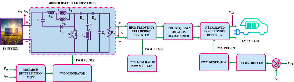
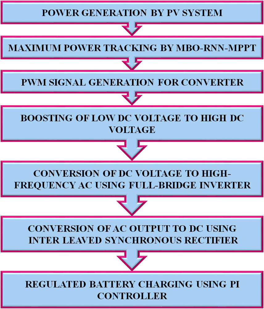
Figure 1(a) depicts the proposed PV based EV charging station, while Figure 1(b) shows the proposed workflow for it. A Modified SEPIC-Luo converter enhances the low voltage generated by PV system, which is the first component of the system. A RNN based MPPT is then used to extract a PV system's peak power, and the Monarch Butterfly optimization algorithm is utilized to adjust its settings. The proposed converter's performance is further improved by PWM pulses produced by a Pulse Width Modulation (PWM) generator. DC voltage is given to the high frequency full bridge inverter that transforms DC into high frequency AC power. Then, it is delivered through a high frequency isolation transformer, which provides isolation between PV system and EV battery. Consequently, the AC power is converted into DC power with the aid of interleaved synchronous rectifier that enhances the efficiency by diminishing conduction losses. Here, a rectifier's operation is controlled by PI controller. A developed system assures an efficient, stable and high performance EV charging from RES. PV system modeling is discussed in the next section.
|
(a) |
|
(b) |
Figure 1. (a) Proposed block diagram and (b) Proposed work flow
PV System
A single-diode equivalent circuit of a series-connected PV cell with an equivalent shunt resistance  and series resistance
  is depicted in Figure 2. When utilizing a PV panel composed of monocrystalline solar cells, the single diode model with five parameters acceptable. The net current
  is,
is,
Where  is denoted by thermal voltage,
 is saturation current of diode, Boltzmann constant is
 , charge of an electron is
  operating temperature is
 , number of series attached cells is
  and
and  is ideality factor. DC/DC converter is needed to boost a voltage from PV system, which is discussed below. The converter used for enhancing the solar voltage is explained as follows.
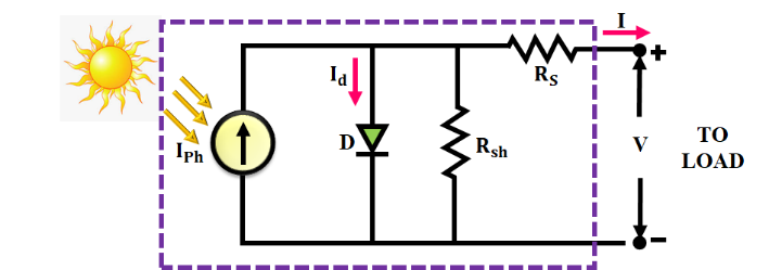
Figure 2. Circuit of PV system
Modified SEPIC-Luo Converter
The circuit design for improved SEPIC-Luo converter used in this research to raise a low voltage of the PV system is presented in Figure 3. It eliminates the requirement for an independent drive circuit for the insulated gate bipolar transistor (IGBT), which is less expensive. Additionally, by attaching the capacitor  in series with the coupled inductor, the dc current flow in the inductor is stopped that prevents saturation. In this configuration, the PV source provides the input voltage, which is processed through a combination of inductors, capacitors and diodes. The switch controls the energy transfer process. The SEPIC portion provides non-inverting output and isolation via a series capacitor while the Luo structure enhances voltage boosting by storing and transferring energy through coupled inductors and an additional filtering stage. The isolation transformer helps reduce electromagnetic interference (EMI) and provides safety. The interleaved synchronous rectification section, involving inductor and diode, further minimizes conduction losses and improves conversion efficiency. Overall, this modified topology ensures high gain, efficient operation and reduced ripple, making it ideal for solar-powered EV charging systems. Figure 4 displays the switching waveform of developed converter.
Stage 1
A switch is turned on at and diodes
  and
and  are reverse and forward biased. In this stage, the coupled inductor’s secondary side and the capacitor
  both provide energy to load. During this time, the output capacitor
  is charged. At the end, a magnetizing current reaches its maximum value. This mode terminates at
  and voltage across a magnetizing inductor
  is identical to an input source voltage
 . A stage 1 operation is provided in Figure 5.
Stage 2
The switch is off at and the diodes and are forward and reverse biased, In this stage, the voltage stress through the switch is decreased and leakage energy supplied by the connected inductor is recovered. The supplies the necessary power to load, while the diodeoffers the channel for magnetizing current. This mode finishes at  and is very short.
In stage 1, the voltage across  is,
is,
| 
| (4) |
By utilizing a voltage second balance principle,
| 
| (5) |
Multiply through by  to eliminate the denominator,
The voltage across the is,
| 
| (11) |
By applying KVL in stage-1, the voltage across the capacitoris,
| 
| (12) |
The static voltage gain is,
| 
| (13) |
Here,  denotes the turns ratio of the coupled inductors. In real-world applications, parasitic losses and non-idealities significantly impact the performance of modified SEPIC-Luo converter. Such factors lead to reduced efficiency, voltage drops and thermal stresses, especially under high load conditions. To address these issues, careful component selection and thermal management are essential and future designs can incorporate soft-switching techniques to minimize switching losses. Regarding mode transitions, the converter operates in two stages and transition is achieved through the controller that continuously monitors input/output voltage and current, adjusting the duty cycle accordingly. Under dynamic conditions, such as fluctuating solar irradiance or variable EV charging loads, RNN based MPPT, which learns from time-series data and adapt in real time, enabling quick and stable tracking of the Maximum Power Point (MPP). This adaptive control ensures that the converter maintains stability, minimizes transients and provides consistent performance despite environmental and load variations. Consequently, the peak power is tracked from PV system with the aid of RNN MPPT algorithm and its performance is enhanced by MBO algorithm which is described as follows.
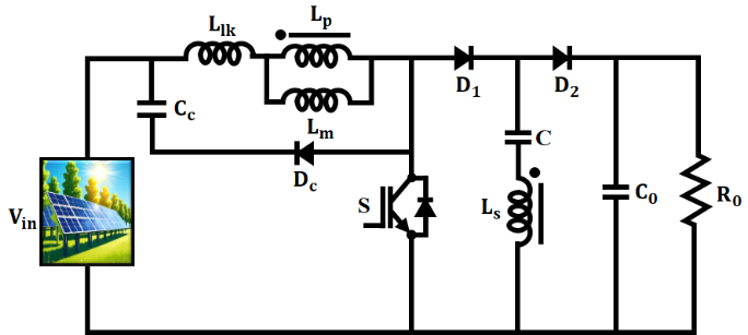
Figure 3. Structure of developed converter
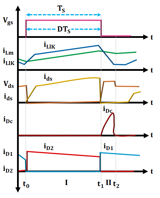
Figure 4. Switching waveform of developed converter
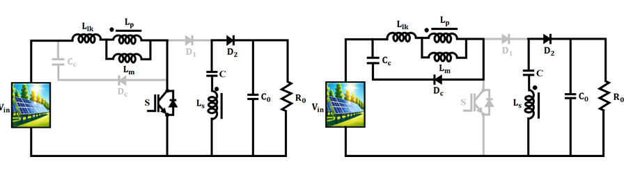
Figure 5. Stages of developed converter
Monarch Butterfly Optimized RNN MPPT
The RNN is well-suited for managing time-dependent data and nonlinear input fluctuations which incorporates feedback connections into its inner layers. This function is essential for monitoring the MPP in real time and guaranteeing the PV array operates at its best. Because the RNN successfully handle nonlinear and time-dependent input fluctuations, it is anticipated to deliver improved accuracy in forecasting the MPP. Unlike conventional techniques, which may suffer from oscillations around the MPP and slow convergence during rapid irradiance or temperature changes, RNN-MPPT can learn and adapt to complex patterns in real time. Its memory-based architecture allows it to retain past information and make more accurate predictions of the MPP, even in fluctuating conditions. Additionally, RNN-MPPT improves tracking speed and accuracy through algorithm optimization, leading to more reliable and effective energy extraction from the PV system. In terms of training data dependency, the RNN requires a moderately sized and representative dataset comprising varying irradiance and temperature profiles to effectively learn temporal patterns.
The structure of the RNN-based MPPT controller for the PV system is shown in Figure 6. RNNs maximize energy harvesting and boost system efficiency by improving MPP tracking accuracy and facilitating quicker responses to environmental changes. When compared to other networks, RNNs are often considered unusual because they are the networks with loops and a hidden state. Based on its structure, the RNN works with sequences and saves prior information in the hidden state. The hidden layer and the RNN output are defined by (14) and (15).
| 
| (14) |
| 
| (15) |
Where and
and  are the appropriate activation functions, given in (16) and (17) respectively;
  are variable matrices and vectors and
 and
and  are input, hidden layer and output vectors, respectively.
| 
| (16) |
| 
| (17) |
The reference current vector , which represents MPP's continuous functioning is the output of this work, which uses irradiation and temperature as 2 input feature vectors to train RNN. The error is the difference between the target expected outcome and the amount of training data, denoted by
 . The training performance is computed using MSE, as indicated in (18). It achieves high prediction outcomes with steadied output voltage when compared to ANN-MPPT. Additionally, it is quickly perceiving the PV's optimal power. MBO mimics the natural interactions between monarch butterflies to solve optimization challenges. MBO has gained attention and been successfully used to address a variety of optimization problems.
| 
| (18) |
The MBO algorithm is selected for parameter tuning due to its strong global search capability, fast convergence speed and ability to avoid local minima, which are critical for optimizing the performance of nonlinear systems like RNN-MPPT in PV applications. Inspired by seasonal migration behaviour of monarch butterflies, MBO balances two distinct migration and adjusting operators, making it highly effective in tuning complex model parameters. Compared to traditional optimization algorithms, MBO demonstrates improved consistency and efficiency in finding optimal solutions with less iteration. Its lightweight computational nature and adaptive behaviour make it well-suited for real-time applications, ensuring that the RNN-MPPT operates at its highest accuracy in tracking MPP under varying environmental conditions. Figure 7 depicts the flowchart for the proposed approach.

Figure 6. RNN based MPPT
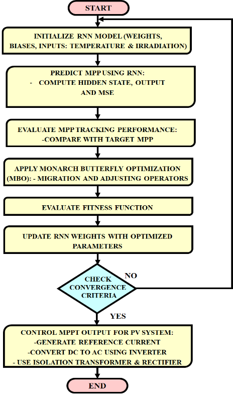
Figure 7. Flowchart of Monarch Butterfly Optimized RNN MPPT
Migration Operator
The solutions in Land 1 are updated using the migration operator in the manner described below: The r_1is estimated as,
| 
| (19) |
When  denotes a random number that is chosen at random from a uniform distribution and
  is the migration time. While
  is found by,
| 
| (20) |
where  is the current generation,
 indicates the
  component of the
  butterfly in the generation
  that indicates the location of the monarch butterfly
  and
and  denotes the component in the generation
  of the
  butterfly, which is chosen at random from Subpopulation
  If
If  then,
then,
| 
| (21) |
Where is the component in the generation of the
  butterfly, and
  is the monarch butterfly’s order selected at random from Subpopulation 2. Here,
  is the migration ratio, the migration operator is,
| 
| (22) |
Adjusting operator
The solutions in Land 2 are updated using the butterfly adjusting operator in the manner described below: Equation (23) updates  if
if  , where
  is a random number that belongs to
  and
and
| 
| (23) |
Where  indicates the element of
  monarch butterfly, where is the best monarch butterfly that has been obtained far in the entire population, and indicates the component of
  butterfly in the generation that indicates where the monarch butterfly
  is located. Equation (24) updates
 .
.
| 
| (24) |
Where is the monarch butterfly’s order selected at random from Land 2 and
 is the component in the generation of the
  butterfly. Equation (7) updates
  which is determined by equation (25) if
  :
:
| 
| (25) |
According to equation (26), Butterfly Adjusting Rate (BAR) and  represents the weighting factor.
| 
| (26) |
The maximum walk step a monarch butterfly may take in a single stride is denoted by , and the step a monarch butterfly
  takes when walking is
  which calculated using Levy flight as,
| 
| (27) |
The hyperparameters used are listed in Table 1. The training of the MPPT model involves a carefully structured dataset composed of irradiance and temperature values as input features and the corresponding reference current as the output label, representing the maximum power point for given environmental conditions. To improve training efficiency and stability, feature normalization is applied using min-max scaling or z-score standardization to ensure that all input values are within a uniform range, preventing gradient vanishing or exploding issues during back propagation. To assess generalization performance and prevent overfitting, a dataset is split into training and validation sets in an 80:20 ratio. Cross validation is used to modify hyperparameters like the number of hidden units, learning rate, activation functions, and epochs in order to achieve the highest prediction accuracy. During training and real-time adaptation, the MBO interacts with the RNN by dynamically adjusting its weights, biases, or learning rate parameters. In offline training, MBO acts as a meta-optimizer to find globally optimal initial parameters, while in online adaptation, it refines these parameters in response to real time fluctuations in solar conditions. This hybrid interaction integrates MBO’s global search capability to guide the RNN toward more accurate and responsive MPPT control under dynamic operating conditions.
MBO helps overcome overfitting issues in neural network training by enabling a more effective and generalized exploration of the parameter space. MBO addresses this by using population-based global search mechanisms, where the migration and adjusting operators diversify the search process and prevent the algorithm from getting trapped in narrow, over-specialized solutions. Its stochastic nature ensures that a wide range of weight and bias configurations are explored, reducing the risk of over-tuning the model to specific patterns in the training set. MBO is computationally lightweight compared to other evolutionary algorithms and is suitable for real-time tuning when efficiently configured. Additionally, by optimizing the network’s hyperparameters and architecture, MBO finds a balance between model complexity and generalization ability. A high frequency inverter then uses a high frequency to convert DC electricity to AC power. The isolation between the PV system and batteries is then provided by the high frequency isolation transformer. Additionally, the AC to DC power conversion is done with the help of interleaved synchronous rectifier. The attained outcomes using the proposed method are analysed as follows.
Table 1. Hyperparameters of MBO-RNN
Parameters | Value |
Number of hidden neurons | 10-20 |
Learning rate | 0.001 |
Epoch | 100 |
Population size | 50 |
Maximum iterations | 100 |
Migration ratio | 0.7 |
Butterfly adjusting rate | 0.3 |
Maximum walk step | 0.1 |
Activation function | Linear |
- RESULTS AND DISCUSSION
The outcomes of a PV based EV charging station utilizing a Matlab/Simulink program are shown in this section. A comparison with other conventional approaches is also included in this section. Table 2 presents the parameters of the planned investigation.
Table 2. Specification of parameters
Parameter | Specification |
PV System |

| 
|

| 12 |

| 
|

| 
|

| 5 |

| 
|
Modified SEPIC-Luo Converter |

| 
|

| 
|

| 
|

| 
|

| 
|
Case 1: Constant Intensity and Temperature
The solar panel’s waveform in constant temperature and intensity condition is illustrated in Figure 8. temperature of PV panel is sustained at a stable value of  while an intensity is maintained at a value of
 . Subsequently, the voltage of PV system stabilizes at
  without oscillations. Furthermore, the input current of developed converter is randomly varied in starting stage and it continued at a steady value of
  with no distortions. Figure 9 shows the waveform of the produced converter. With a modified SEPIC-Luo converter, the output voltage is gradually raised to 420 V. Additionally, an output current is gradually increased and maintained at 5.8 A without distortion. The waveform of power is indicated in Figure 10. The input power is arbitrarily changed in initial time and it maintained at
  Likewise, an output power is gradually increased and it settled at a value of
  .
.

Figure 8. Waveform of PV system
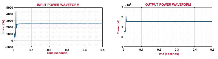
Figure 9. Waveform of developed converter
Figure 10. Waveform of power
Case 2: Varying Intensity and Temperature
Figure 11 depicts a waveform of PV panel in changing temperature and intensity condition. While PV panel's intensity is varied in the beginning and maintained at 1000 (W⁄(Sq.m)), a panel's temperature is varied in the beginning and settles at 35°C.In a similar manner, after being originally altered, the voltage remained constant at 100 V without distortion. In addition, an input current is randomly changed and maintained at 25 A without oscillating. Figure 12 shows the output waveform of the proposed converter. An output voltage is gradually raised with random variations and is continued at 420 V. Also, an output current is slowly improved and maintained at a value of 5.8 A. A power waveform is shown in Figure 13. Initially, the input power is varied arbitrarily and it settled at 2500 W while the output power is slowly improved and it sustained at a value of  with no fluctuations.
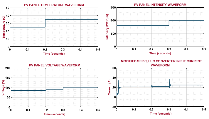
Figure 11. Waveform of PV panel
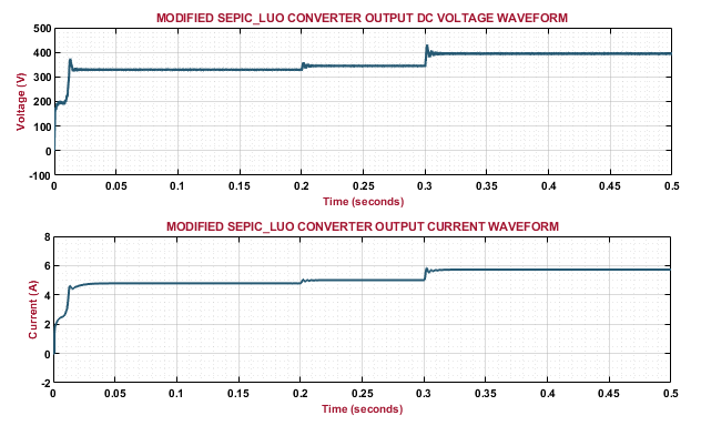
Figure 12. Output waveform of converter
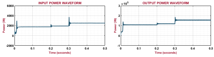
Figure 13. Waveform of power
Figure 14 presents the waveform of high frequency transformer. Initially, the high frequency inverter’s voltages varied and it sustained at a value of 400V in the entire system. Additionally, the voltage of high frequency transformer is slowly enhanced and it settled at a constant value of 100V. Figure 15 illustrates the waveform of synchronous rectifier. The output voltage of rectifier 1 has variations in the starting period and it continued at a value of 110V while an output current is gradually changed and it continued at a steady value of 3.2A. Likewise, the output voltage of rectifier 2 changed and it sustained at a value of 110V.Furthermore, the output current is gradually increased and stabilized at 3.2A without oscillations. A waveform of the interleaved synchronous rectifier is shown in Figure 16, which combines the output of synchronous rectifiers 1 and 2. An output voltage is progressively raised and kept at a steady 220 V throughout the system. The battery waveform is depicted in Figure 17. An overall mechanism maintains a battery's State of Charge (SOC) at 80%. Also, a voltage of battery is settled at 120 V while the battery current has reduced significantly.
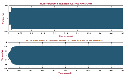
Figure 14. Waveform of high frequency inverter and transformer
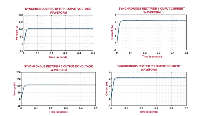
Figure 15. Waveform of synchronous rectifier
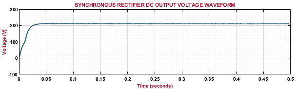
Figure 16. Waveform of interleaved synchronous rectifier
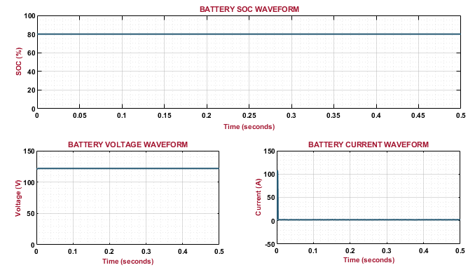
Figure 17. Waveform of battery
Comparative Analysis
Figure 18 represents the analysis of efficiency for Luo [21], enhanced SEPIC [22] and developed converter, which has highest efficiency of 97.44% than other approaches, reveals that the overall performance of system is enhanced. Key factors contributing to this high efficiency include the use of fewer switching components operating under soft-switching conditions, which reduces switching losses and the presence of coupled inductors that enhance voltage conversion with minimal conduction loss. The improved control strategy ensures that the converter operates close to its optimal duty cycle, thereby minimizing both switching and conduction losses across various load conditions.
The analysis of tracking efficiency for developed MPPT approach with Improved Perturb& Observe (P&O) [23], Evolutionary Algorithm (EA) [24] and Fuzzy approach [25] is revealed in Figure 19. The developed approach outperforms than conventional methods with efficiency of 98.8%, demonstrating its ability in maintaining accurate tracking performance. RNNs adopt their memory and sequence-processing capabilities to predict optimal operating points based on past and current data. RNN-MPPT also offers faster convergence and higher tracking accuracy without the need for manually defined rules or extensive parameter tuning.
The voltage gain analysis between non-isolated high step-up [26], Switched inductor Boost [27], high step-up [28] and developed converter is depicted in Figure 20 and Table 3. The other converters exhibit lowest voltage gain than proposed converter, which is a more effective solution for high voltage conversion applications. The comparative analysis of maximum voltage stress on diode for Z-source based high step-up [29], Quasi Z-source based high step-up [30] and developed converter is seen in Figure 21 and Table 4. It indicates the better performance of developed converter in reducing voltage stress on diode across distinct duty cycles, which enhances the efficiency and reliability of the system. This reduction in diode stress directly enhances the converter's reliability by minimizing the electrical and thermal stress imposed on the diodes during operation. This not only improves the overall lifespan of the power converter, but also ensures stable performance under varying load and environmental conditions.
The convergence graph in Figure 22 compares the performance of MBO, GA and PSO of their objective function values over successive iterations. X-axis denotes the number of iterations, while Y-axis shows the objective function value, which is typically to be minimized or maximized depending on the optimization goal. The graph clearly demonstrates that MBO achieves a faster and more efficient convergence, reaching a lower objective function value in less iteration compared to GA and PSO. This indicates that MBO not only locates the optimal solution more rapidly but also maintains better accuracy and stability across iterations.
Table 5 presents a comparative analysis of three converter topologies based on key parameters: number of components, voltage gain and efficiency. A SEPIC converter has efficiency of 92.56%.and Luo converter has a slightly simpler capacitor-inductor configuration with efficiency of 93.22%. In contrast, the proposed converter integrates the strengths of both resulting in the highest voltage gain of 14 and a significantly improved efficiency of 97.44%. It exhibits a 5.27% improvement over the SEPIC converter and a 4.53% improvement over the Luo converter. Although the proposed design includes a higher component count, especially in inductors and diodes, it justifies the increase with superior performance, making it highly suitable for high-gain, energy-efficient applications such as solar-powered EV charging systems. Arrived conclusions from the proposed work are summarized in Table 6.
Table 6 presents a comparison of the Root Mean Square Error (RMSE) values used in MPPT applications. RMSE metric quantifies the deviation between both an actual and predicted values, where a lower RMSE indicates higher accuracy. Among the three algorithms, MBO achieves the lowest RMSE of 0.0125, demonstrating superior precision and convergence capability. PSO performs moderately with an RMSE of 0.0258, while GA shows the highest error at 0.0324, indicating relatively lower accuracy.
Figure 18. Analysis of efficiency
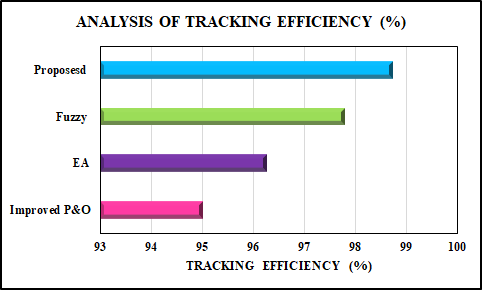
Figure 19. Analysis of tracking efficiency

Figure 20. Comparison of voltage gain of modified SEPIC-Luo with existing ones for varying duty cycle
Table 3. Voltage gain comparison for different duty cycles
Duty cycle (D) | Non-isolated high step-up | Switched Inductor Boost | High step-up DC-DC | Proposed converter |
0.60 | 7 | 5 | 4.5 | 10 |
0.65 | 9 | 6 | 5 | 13 |
0.70 | 12 | 8 | 6.5 | 18 |
0.75 | 16 | 10 | 8 | 25 |
0.80 | 21 | 13 | 10 | 35 |
0.85 | 28 | 17 | 4.5 | 55 |
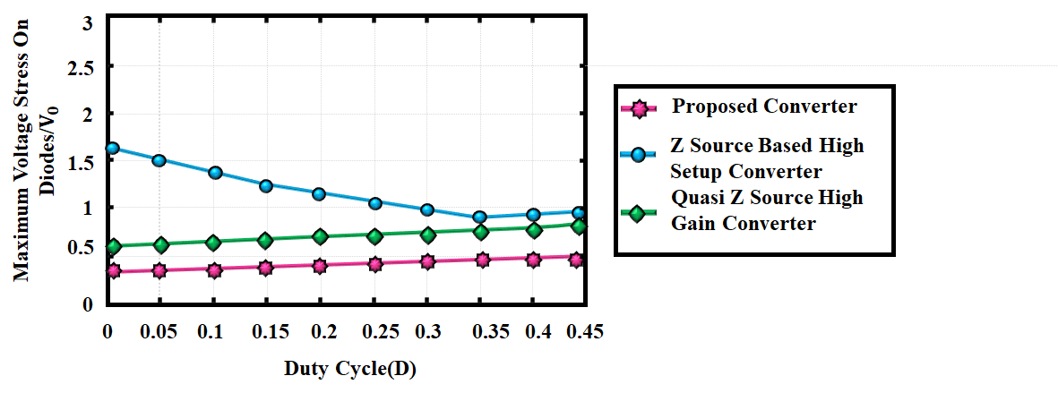
Figure 21. Comparison of voltage stress
Table 4. Comparison of voltage stress for varying duty cycle
Duty cycle (D) | Proposed converter | Z-source high step-up | Quasi Z-source high gain |
0.05 | 0.5 | 1.7 | 0.85 |
0.10 | 0.5 | 1.6 | 0.87 |
0.15 | 0.5 | 1.6 | 0.88 |
0.20 | 0.5 | 1.4 | 0.9 |
0.25 | 0.5 | 1.3 | 0.92 |
0.30 | 0.5 | 1.2 | 0.93 |
0.35 | 0.5 | 1.15 | 1.94 |
0.40 | 0.5 | 1.1 | 0.95 |
0.45 | 0.5 | 1.05 | 0.95 |
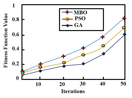
Figure 22. Comparison of convergence
Table 5. Comparison of converters
Converters | No. of components | Gain | Efficiency (%) |
Capacitors | Switches | Diodes | Inductors |
SEPIC | 3 | 1 | 1 | 2 | 10 | 92.56 |
Luo | 2 | 1 | 2 | 1 | 12 | 93.22 |
Proposed | 3 | 1 | 3 | 4 | 14 | 97.44 |
Table 6. Comparison of RMSE
Converters | RMSE |
GA | 0.0324 |
PSO | 0.0258 |
MBO | 0.0125 |
- CONCLUSIONS
Key results: The solar powered EV charging station with a modified SEPIC-Luo converter is presented in this research. The overall research is implemented in MATLAB/Simulink tool, reveals that it attains the converter efficiency of 97.44 %, tracking efficiency of 98.8%, ensuring the efficient and stable performance. The proposed converter shows an efficiency improvement of 8.27% over Luo [21] and 2.39% over enhanced SEPIC [22]. The MBO is 4.45% faster than Improved P&O [23], 2.81% faster than EA [24] and 1.44% faster than Fuzzy [25] approaches.
Broader significance: The modified SEPIC-Luo converter aids in increasing gain and efficiency, leading to smoother operation. Then, the RNN based MPPT algorithm rapidly responds to fluctuations, confirming that the PV system functions at its MPP. Additionally, MBO helps in finding an optimal set of hyper parameters for the RNN, leading to better efficiency and accuracy in tracking the MPP. Additionally, the isolation transformer and high frequency full bridge inverter improve efficiency and guarantee component safety. Primarily, the isolation transformer provides galvanic isolation between the input and the output, preventing direct electrical contact and thereby protecting users and sensitive equipment from electric shocks or faults. It also plays a key role in mitigating ground loop issues, which can otherwise cause unwanted current paths and noise interference. Finally, the interleaved synchronous rectifier improves the dynamic response of the system, enabling improved management of load changes and transient conditions. Thus, the proposed system offers a forward-looking and sustainable solution that outweighs initial concerns, making it a valuable investment for future energy infrastructure. While the upfront cost may be higher due to advanced components and intelligent control algorithms, these are justified by the system’s high efficiency, reduced energy losses and long-term operational savings. Moreover, the scalability of the design allows it to be modular, easily expanded to accommodate multiple EVs or integrated into smart grids. In future, this work can be implemented in a hardware prototype for validating the real-time performance.
REFERENCES
- N. Kumar, H. K. Singh and R. Niwareeba, “Adaptive Control Technique for Portable Solar Powered EV Charging Adapter to Operate in Remote Location,” in IEEE Open Journal of Circuits and Systems, vol. 4, pp. 115-125, 2023, https://doi.org/10.1109/OJCAS.2023.3247573.
- S. Zhou et al., “Dynamic EV Charging Pricing Methodology for Facilitating Renewable Energy with Consideration of Highway Traffic Flow”, in IEEE Access, vol. 8, pp. 13161-13178, 2020, https://doi.org/10.1109/ACCESS.2019.2958403.
- A. K. Karmaker, M. A. Hossain, H. R. Pota, A. Onen and J. Jung, “Energy Management System for Hybrid Renewable Energy-Based Electric Vehicle Charging Station,” in IEEE Access, vol. 11, pp. 27793-27805, 2023, https://doi.org/10.1109/ACCESS.2023.3259232.
- B. Singh, A. Verma, A. Chandra and K. Al-Haddad, “Implementation of Solar PV-Battery and Diesel Generator Based Electric Vehicle Charging Station,” in IEEE Transactions on Industry Applications, vol. 56, no. 4, pp. 4007-4016, 2020, https://doi.org/10.1109/TIA.2020.2989680.
- G. H. Reddy, S. R. Depuru, S. Gope, B. V. Narayana and M. N. Bhukya, “Simultaneous Placement of Multiple Rooftop Solar PV Integrated Electric Vehicle Charging Stations for Reliability Benefits,” in IEEE Access, vol. 11, pp. 130788-130801, 2023, https://doi.org/10.1109/ACCESS.2023.3335093.
- Y. Yang, H. G. Yeh and N. C. T. Dam, “Optimal Infrastructure Design and Power Management for a Photovoltaic and Battery Assisted Electric Vehicle Charging Station in Southern California,” in IEEE Access, vol. 12, pp. 54101-54114, 2024, https://doi.org/10.1109/ACCESS.2024.3386659.
- S. Mateen, A. Haque, V. S. B. Kurukuru and M. A. Khan, “Discrete Stochastic Control for Energy Management With Photovoltaic Electric Vehicle Charging Station,” in CPSS Transactions on Power Electronics and Applications, vol. 7, no. 2, pp. 216-225, 2022, https://doi.org/10.24295/CPSSTPEA.2022.00020.
- S. Bagherwal and S. Mahapatra, “Enhanced Stability and Control of Solar Powered EV Charging Stations Using Disturbance Observer-Based Adaptive Sliding Mode Control for DC Voltage Stabilization,” in IEEE Access, vol. 12, pp. 183293-183311, 2024, https://doi.org/10.1109/ACCESS.2024.3511637.
- K. S. Kavin, P. Subha Karuvelam, M. Devesh Raj, and M. Sivasubramanian, “A Novel KSK Converter with Machine Learning MPPT for PV Applications,” Electric Power Components and Systems, pp. 1-19, 2024, https://doi.org/10.1080/15325008.2024.2346806.
- C. H. Lin, M. S. Khan, J. Ahmad, H. D. Liu and T. C. Hsiao, “Design and Analysis of Novel High-Gain Boost Converter for Renewable Energy Systems (RES),” in IEEE Access, vol. 12, pp. 24262-24273, 2024, https://doi.org/10.1109/ACCESS.2024.3365705.
- É. A. Tonolo, J. W. M. Soares, E. F. R. Romaneli and A. A. Badin, “Current Sensorless MPPT With a CCM Interleaved Boost Converter for Renewable Energy System,” in IEEE Transactions on Power Electronics, vol. 37, no. 9, pp. 11296-11304, 2022, https://doi.org/10.1109/TPEL.2022.3166747.
- O. Abdel-Rahim, M. L. Alghaythi, M. S. Alshammari and D. S. M. Osheba, “Enhancing Photovoltaic Conversion Efficiency With Model Predictive Control-Based Sensor-Reduced Maximum Power Point Tracking in Modified SEPIC Converters,” in IEEE Access, vol. 11, pp. 100769-100780, 2023, https://doi.org/10.1109/ACCESS.2023.3315150.
- F. Ghasemi, M. R. Yazdani and M. Delshad, “Step-Up DC-DC Switching Converter with Single Switch and Multi-Outputs Based on Luo Topology,” in IEEE Access, vol. 10, pp. 16871-16882, 2022, https://doi.org/10.1109/ACCESS.2022.3150316.
- K. S. Kavin, P. Subha Karuvelam, Murali Matcha, and Suresh Vendoti, “Improved BRBFNN-based MPPT algorithm for coupled inductor KSK converter for sustainable PV system applications,” Electrical Engineering, pp. 1-23, 2025, https://doi.org/10.1007/s00202-025-02952-9.
- N. F. Ibrahim, et al., “Operation of Grid-Connected PV System With ANN-Based MPPT and an Optimized LCL Filter Using GRG Algorithm for Enhanced Power Quality,” in IEEE Access, vol. 11, pp. 106859-106876, 2023, https://doi.org/10.1109/ACCESS.2023.3317980.
- A. A. Salem, N. A. N. Aldin, A. M. Azmy and W. S. E. Abdellatif, “Implementation and Validation of an Adaptive Fuzzy Logic Controller for MPPT of PMSG-Based Wind Turbines,” in IEEE Access, vol. 9, pp. 165690-165707, 2021, https://doi.org/10.1109/ACCESS.2021.3134947.
- A. Hilali, Y. Mardoude, A. Essahlaoui, A. Rahali, and N. E. Ouanjli, “Migration to solar water pump system: Environmental and economic benefits and their optimization using genetic algorithm Based MPPT,” Energy Reports, vol. 8, pp. 10144-10153, 2022, https://doi.org/10.1016/j.egyr.2022.08.017.
- E. S. Wirateruna, and A. F. A. Millenia, “Design of MPPT PV using particle swarm optimization algorithm under partial shading condition,” International Journal of Artificial Intelligence & Robotics (IJAIR), vol. 4, no. 1, pp.24-30, 2022, https://doi.org/10.25139/ijair.v4i1.4327.
- Z. B. Bel, H. Salah, S. Krim, M. A. Hajjaji, B. M. Alshammari, K. Alqunun, A. Alzamil, and T. Guesmi, “A new efficient cuckoo search MPPT algorithm based on a super-twisting sliding mode controller for partially shaded standalone photovoltaic system,” Sustainability, vol. 15, no. 12, pp. 9753, 2023, https://doi.org/10.3390/su15129753.
- J. Gholami, K. K. A. Ghany, and H. M. Zawbaa, “A novel global harmony search algorithm for solving numerical optimizations,” Soft Computing, vol. 25, pp. 2837-2849, 2021, https://doi.org/10.1007/s00500-020-05341-5.
- S. Sivarajeswari, and D. Kirubakaran, “Design and Development of Efficient Luo Converters for DC Micro Grid,” The International Journal of Electrical Engineering & Education, vol. 60, no. 1S, pp. 40-48, 2023, https://doi.org/10.1177/0020720919845152.
- S. Esmaeili, M. Shekari, M. Rasouli, S. Hasanpour, A. A. Khan and H. Hafezi, "High Gain Magnetically Coupled Single Switch Quadratic Modified SEPIC DC-DC Converter," in IEEE Transactions on Industry Applications, vol. 59, no. 3, pp. 3593-3604, 2023, https://doi.org/10.1109/TIA.2023.3250405.
- P. Manoharan, U. Subramaniam, T. S. Babu, S. Padmanaban, J. B. Holm-Nielsen, M. Mitolo and S. Ravichandran,“Improved perturb and observation maximum power point tracking technique for solar photovoltaic power generation systems,” IEEE Systems Journal, vol. 15, no. 2, pp. 3024-3035, 2020, https://doi.org/10.1109/JSYST.2020.3003255.
- E. Mendez, A. Ortiz, P. Ponce, I. Macias, D. Balderas and A. Molina, “Improved MPPT algorithm for photovoltaic systems based on the earthquake optimization algorithm,” Energies, vol. 13, no. 12, pp. 3047, 2020, https://doi.org/10.3390/en13123047.
- D. N. Luta and A. K. Raji,“Fuzzy rule-based and particle swarm optimisation MPPT techniques for a fuel cell stack,” Energies, vol. 12, no. 5, pp. 936, 2019, https://doi.org/10.3390/en12050936.
- M. A. Salvador, J. M. de Andrade, T. B. Lazzarin, and R. F. Coelho, “Nonisolated high-step-up dc–dc converter derived from switched-inductors and switched-capacitors,” IEEE Transactions on Industrial Electronics, vol. 67, no. 10, pp. 8506–8516, 2020, https://doi.org/10.1109/TIE.2019.2949535.
- S. Sadaf, M. S. Bhaskar, M. Meraj, A. Iqbal, and N. Al-Emadi, “A novel modifed switched inductor boost converter with reduced switch voltage stress,” IEEE Transactions on Industrial Electronics, vol. 68, no. 2, pp. 1275–1289, 2021, https://doi.org/10.1109/TIE.2020.2970648.
- S. Tangavelu and P. Umapathy, “Design of new high step-up dc-dc converter topology for solar pv applications,” International Journal of Photo energy, vol. 2021, 2021, https://doi.org/10.1155/2021/7833628.
- R. Rahimi, S. Habibi, M. Ferdowsi, and P. Shamsi, “Z-source-based high step-up DC–DC converters for photovoltaic applications,” IEEE J. Emerg. Sel. Top. Power Electron. Vol. 10, no. 4, pp. 4783–4796, 2022, https://doi.org/10.1109/JESTPE.2021.3131996.
- A. Mahmood, “A non-isolated quasi-Z-source-based high-gain DC–DC converter,” Int. J. Circ. Teor. Appl. vol. 50, no. 2, pp.653–682, 2022, https://doi.org/10.1002/cta.3162.
S. L. Sreedevi (Solar-Powered EV Charging Using Modified SEPIC-Luo Converter with Recurrent Neural Network Technique)