Buletin Ilmiah Sarjana Teknik Elektro ISSN: 2685-9572
Implementation of a Synergetic Controller for a 2-DOF Helicopter on an Embedded Platform Using an STM32 Microcontroller
Nguyen Xuan Chiem 1, Tran Cong Phan 1, Pham Duy Thai 2, Bui Xuan Hai 1
1 Department of Automation and Computing Techniques, Le Quy Don Technical University, Hanoi, Vietnam
2 Department of Biomedical Engineering, Le Quy Don Technical University, Hanoi, Vietnam
ARTICLE INFORMATION |
| ABSTRACT |
Article History: Received 01 May 2025 Revised 18 June 2025 Accepted 01 July 2025 |
| 
This study introduces the development of a synergetic control scheme for a two-degree-of-freedom (2-DOF) helicopter, integrated into an embedded system utilizing the STM32 microcontroller. A discrete-time controller is formulated for both pitch and yaw motion, relying on stable manifold design within the framework of synergetic control. Lyapunov-based analysis is used to ensure system stability. The controller is implemented on an STM32F4 device and coded in the C programming language. System performance is assessed through numerical simulations and real-time testing, with results demonstrating strong control precision and feasibility on the physical experimental platform. |
Keywords: 2-DOF Helicopter; Synergetic Controller; Embedded System; Lyapunov Function; ADAR |
Corresponding Author: Bui Xuan Hai, Department of Automation and Computing Techniques, Le Quy Don Technical University, Hanoi, Vietnam. Email: buixuanhai.mta@gmail.com |
This work is licensed under a Creative Commons Attribution-Share Alike 4.0 
|
Document Citation: N. X. Chiem, T. C. Phan, P. D. Thai, and B. X. Hai, “Implementation of a Synergetic Controller for a 2-DOF Helicopter on an Embedded Platform Using an STM32 Microcontroller,” Buletin Ilmiah Sarjana Teknik Elektro, vol. 7, no. 2, pp. 253-269, 2025, DOI: 10.12928/biste.v7i2.13410. |
- INTRODUCTION
In recent years, there has been growing interest from both the academic community and industry in developing high-accuracy control solutions for small-scale aerial platforms such as the Two-Degree-of-Freedom (2-DOF) helicopter. The control challenges arise primarily from the system’s highly nonlinear behavior, strong inter-axis coupling, and vulnerability to external disturbances. These characteristics often limit the effectiveness of conventional control methods in ensuring stable and precise operation [1]–[14].
Since testing control algorithms on full-scale helicopters is not feasible in academic environments, various compact experimental models have been created for education and research in flight control. Among them, the two-degree-of-freedom (2-DOF) helicopter setup has gained popularity due to its simplicity and versatility [10]-[17]. Many control strategies—both linear and nonlinear—have been proposed for managing this system [18]-[69]. Traditional linear controllers such as Proportional-Integral-Derivative (PID), Linear Quadratic Regulator (LQR), and model-driven adaptive or optimal control techniques are frequently applied [18]-[25]. For example, the use of an adaptive LQR method on the Quanser 2-DOF platform is detailed in [22], while [24] presents an optimal LQR design for attitude stabilization. Another contribution [26] utilizes extended linearization techniques for trajectory tracking purposes. In addition, [27] proposes a Multi-step Q-learning (MsQL) approach to address output regulation challenges in the same system. Although linear methods are generally straightforward to implement, their performance often degrades under wide variations in operating conditions.
Due to the complex nonlinear behavior of helicopter systems and their high sensitivity to parameter uncertainties and environmental disturbances, designing effective control strategies presents significant challenges [28]-[50]. Traditional linear controllers often fall short when it comes to meeting the stringent demands of real-world applications [51]-[73]. In response, recent studies have increasingly emphasized the formulation of adaptive and robust nonlinear control approaches to better manage system nonlinearities and external variations. For example, [36] proposed a backstepping method using saturation-based feedback to enhance trajectory tracking. In a related effort [37], an adaptive nonlinear backstepping technique was developed to individually manage pitch and yaw dynamics. Additionally, [60] introduced a fractional-order sliding mode control (SMC) approach applied to the Quanser AERO 2-DOF platform, where a specially designed sliding surface helped reduce chattering effects. Other works [72][73] have explored synergetic control frameworks employing varied manifold structures tailored to this system.
Synergetic control, a contemporary nonlinear control methodology, has proven highly effective for stabilizing complex dynamic systems. By designing appropriate control manifolds, this approach ensures global convergence of system trajectories and offers strong resistance to external disturbances [72]-[89]. The foundational principles of synergetic control were pioneered by Professor A. A. Kolecnikov and his team, as elaborated in works [74]-[79]. Numerous engineering applications have successfully adopted this control framework [80]-[89], consistently demonstrating its advantages over traditional control techniques in terms of robustness and performance. Concurrently, the deployment of advanced control algorithms on high-performance yet cost-effective embedded platforms, such as STM32 microcontrollers, has become increasingly widespread. This trend is driven by the STM32’s powerful processing capabilities, comprehensive hardware features, and ease of integration into real-time systems.
This research aims to develop and deploy a synergetic control approach for a 2-DOF helicopter, implemented on an STM32 microcontroller-based embedded system. The goal is to verify its applicability and performance when subjected to realistic operational limitations. The main contributions of this paper include: (1) constructing a mathematical representation of the 2-DOF helicopter model tailored for the application of synergetic control; (2) designing a discrete-time synergetic controller that ensures both stability and desired performance; (3) coding and executing the control strategy using the C programming language on the STM32 platform, and integrating it with the actual helicopter system; and (4) conducting real-time experiments to evaluate the system’s tracking capability, accuracy, and robustness in practical conditions.
The rest of the paper is organized as follows. Section 2 introduces the mathematical modeling of the 2-DOF helicopter. In Section 3, an in-depth explanation of synergetic control theory is provided, followed by the formulation of a discrete-time controller specifically adapted to the system’s dynamics. Section 4 focuses on the practical implementation of the control algorithm using an STM32 microcontroller, detailing the experimental setup, test procedures, and performance analysis. Finally, Section 5 summarizes the findings and suggests potential directions for future enhancements.
- METHODS
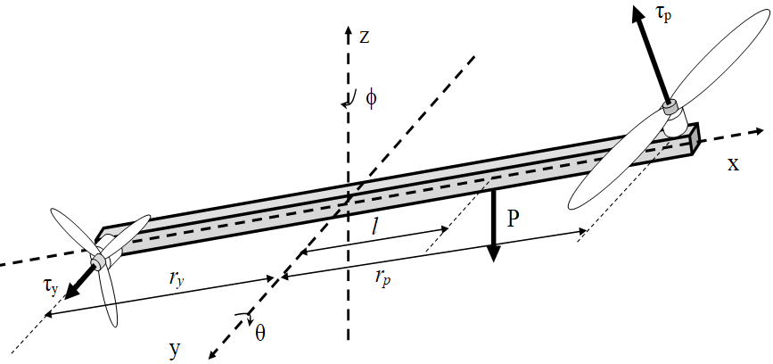
The two-degree-of-freedom (2-DOF) helicopter model comprises a beam mounted on a base that permits independent rotations around both the vertical and horizontal axes, as shown in Figure 1. At each end of the beam, a brushless DC (BLDC) motor drives a rotor—one functioning as the main rotor and the other as the tail rotor. By adjusting the speed of these motors, the system can achieve motion in the elevation (pitch) and azimuth (yaw) directions [65]-[73].
Figure 1. Dynamics of the 2-DOF Helicopter
- Mathematical Model of the BLDC Motor
The structure of a brushless DC (BLDC) motor is similar to that of a permanent magnet synchronous machine. However, due to the placement of the permanent magnets on the rotor, there are certain differences in the dynamic characteristics. The armature winding model of the BLDC motor is described as follows. By applying Kirchhoff’s voltage law to the three-phase BLDC motor and neglecting mutual inductance [89][90], we obtain:
where  ,
,  ,
,  denote the input voltages for phases
  ,
,  , and
, and  , respectively;
  ,
,  ,
,  represent the corresponding phase currents; L and R represent the phase inductance and resistance; and
  ,
,  ,
,  are the back electromotive forces (EMFs) induced in each phase. The generated torque is affected by the presence of permanent magnets, owing to the trapezoidal nature of the flux linkage. As a result, the torque can be expressed as:
| 
| (2) |
The resulting torque  can be calculated as follows:
Where,  is rotor angle in electrical degree ;
  is rotor speed (rad/sec);
  is rotor angle mechanical:
| 
| (4) |
The dynamic equation of the motion system, including friction, load torque, and inertia, is:
| 
| (5) |
Where, is Electric Torque,  is Load (Mechanical) Torque,
  is friction constant,
  is Rotor Inertia. The rotational speed of the motor is synchronized with the speed of the propeller mounted on the rotor and generates thrust along the pitch and yaw axes of the 2-DOF helicopter model.
- Dynamic Model of the 2-DOF Helicopter
The 2-DOF helicopter system is modeled using a number of simplifying assumptions [18],[73]:
- The dynamics of the motors are significantly faster than the overall system dynamics and thus can be ignored.
- The system experiences viscous-type friction.
- The interaction between the rotors and air follows the principles of flow theory.
As depicted in Figure 1, the model includes two thrust components:  and
and  , which are exerted along the pitch and yaw directions, respectively. These torques are applied at distances
  and
and  from their corresponding rotational axes. The helicopter experiences a gravitational force
  acting downward at the nose. The center of mass is offset by a distance
  (m) from the pitch axis along the longitudinal body of the helicopter. By applying coordinate transformations, the location of the center of mass is expressed using generalized coordinates as follows:
| 
| (6) |
The formula used to calculate gravitational potential energy is:
| 
| (7) |
The formula for calculating total kinetic energy due to moments of inertia is as follows
| 
| (8) |
Where:
Let  and
and  denote the total rotational kinetic energies associated with the pitch and yaw axes, respectively, while
  represents the translational kinetic energy due to the motion of the system's center of mass. The terms
  and
and  refer to the equivalent moments of inertia for the pitch and yaw motors. By taking the time derivatives of the equations given in (6), and substituting the resulting expressions into equations (9) and (8), we can derive the complete expression for the system's total kinetic energy as follows:
| 
| (10) |
Based on the Euler-Lagrange equations of motion, we have:
| 
| (11) |
| 
|
Where the Lagrangian function  is defined as
  , calculated from (10) and (7), as follows:
| 
| (12) |
The corresponding generalized forces are given by
The parameters  and
and  represent the damping coefficients associated with rotational motion about the pitch and yaw axes, respectively. The torques exerted on these axes are given by:
In this context:
 and
and  denote the primary lift torques generated by the pitch and yaw motors along their respective axes.
 represents the influence of the yaw motor on the pitch axis, while
 accounts for the effect of the pitch motor on the yaw axis.
These cross-coupling torques arise due to the spatial configuration and aerodynamic interactions between the two rotors. The torque components are identified and quantified as follows:
| 
| (13) |
| 
|
From equations (11), (12), and (13), we obtain:
| 
| (14) |
Simplifying equation (14), we obtain:
| 
| (15) |
Similarly to the pitch axis, the equation of motion for the yaw axis is derived as follows:
| 
| (16) |
According to the dynamic behavior of the BLDC motors, when their response times are significantly faster than those of the pitch and yaw axes, the torques exerted on the system can be approximated as:
Here,  and
and  represent the input voltages applied to the pitch and yaw BLDC motors, respectively. The constants
  and
and  denote the thrust coefficients for the pitch and yaw motors, whereas
  and
and  account for the cross-axis torque effects induced by the yaw motor on the pitch axis and vice versa. For implementation on embedded digital platforms, the continuous-time model is converted into discrete-time form. Employing a finite-difference approach with a sampling interval
  , and based on the equations (15) and (16), the discrete-time representation of the system dynamics is obtained as follows:
| 
| (17) |
| 
| (18) |
The values  ,
,  are calculated from the torques
  ,
,  according to the following formulas:
| 
| (19) |
- SYNTHESIS OF DISCRETE SYNERGETIC CONTROL LAW FOR THE 2-DOF HELICOPTER SYSTEM
The discrete synergetic controller is developed using the Analytical Design of Aggregate Regulators (ADAR) framework. This approach involves a systematic design methodology, which can be outlined in the following key steps. Consider a nonlinear discrete-time system governed by a general difference equation of the form:
| 
| (20) |
Where  is the state vector, and
  is the control input vector.
The initial step involves defining a macro variable (also referred to as a manifold) as a function of the system's state at time step kkk, expressed as  . The objective of the control law is to constrain the system dynamics such that the trajectory remains on the manifold, i.e.,
  . The structure of this macro variable can be tailored by the designer based on specific performance criteria or control objectives [72]–[79].
In practice, the macro variable may be chosen as a linear combination of the state variables for simplicity. This procedure can be extended to multiple control loops by introducing additional manifolds for each control direction. The evolution of each macro variable is typically governed by a dynamic equation of the form given in (10), which defines the desired closed-loop behavior.
| 
| (21) |
Here,  is a tunable parameter that governs how quickly the system states converge to the manifold defined by the macro-variable. Equation (10) serves as the foundation for deriving the control input
  . To summarize, the introduction of each synergetic manifold imposes an additional constraint within the state-space, effectively lowering the system’s dynamic order and guiding its evolution toward overall asymptotic stability.
- Synthesis of the Digital Synergetic Control Law for the 2-DOF Helicopter System
The control objective for stabilizing the 2-DOF helicopter system is to ensure the helicopter remains stable at the desired position. In this paper, the synergetic control law synthesis method is applied independently for each pitch and yaw channel. According to synergetic control theory, the authors select the invariant manifold for the pitch channel corresponding to the control objective as follows:
| 
| (22) |
As the initial step in the control design, the mathematical model presented in equation (17) is analyzed. It is observed that variations in the control inputs influence the behavior of the pitch dynamics. Consequently, the first synergetic manifold is constructed to reflect this coupling effect and is defined as:
| 
| (23) |
Here, the condition  ensures that the manifold described in equation (23) asymptotically converges to the target reference value
  , while remaining within the operational bounds of the system. Following the control design methodology previously outlined, the macro-variable
  is required to fulfill the solution of the associated canonical functional equation, which governs the desired evolution of the manifold dynamics:
| 
| (24) |
Substituting expression (23) into equation (24), we obtain:
| 
| (25) |
Substituting equation (17) into equation (25), the control law for the pitch channel is obtained as follows:
| 
| (26) |
| 
|
Similarly, the control law for the yaw channel is derived as follows:
| 
| (27) |
| 
|
From the control laws for the pitch axis (26) and the yaw axis (27), based on equation (19), the control voltage laws , for each motor along the respective axes are obtained.
- Stability Analysis
A Lyapunov function is selected in the following form:
| 
| (28) |
The variation of 𝑉 along the solution of equations (17) and (18) with the control law is given by:
| 
| (29) |
Substituting the manifold form (23) for the pitch and yaw channels into (29), we obtain:
| 

| (30) |
Simplifying equation (30), we obtain:
| 
| (31) |
According to the condition in expression (24), we have  , implying that the system is stable in the Lyapunov sense.
- RESULT AND DISCUSSION
- Description of the Experimental Setup for the 2-DOF Helicopter System
To validate the effectiveness of the proposed control strategy applied through the input signals up,k and uy,k, a series of experiments were conducted. The experimental platform consists of a custom-built 2-DOF helicopter prototype, along with a complete test bench and instrumentation setup. Figure 2 and Figure 3 illustrate the hardware configuration and the experimental arrangement used in the study.
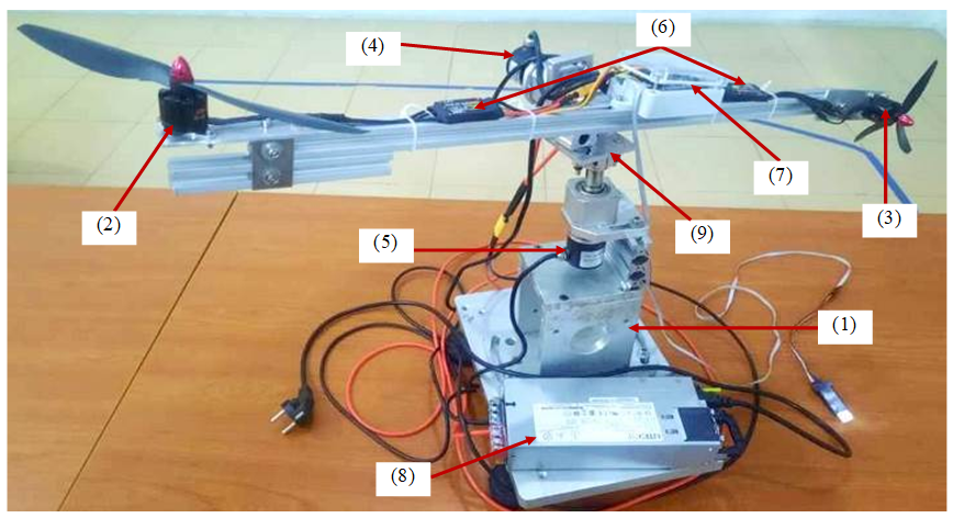
Figure 2. The physical model of the 2-DOF helicopter: (1) Base, (2) Pitch axis BLDC motor, (3) Yaw axis BLDC motor (4) Pitch angle encoder, (5) Pitch angle encoder, (6) BLDC motor drivers (ESC), (7) STM32F411 board, (8) Power 24V, (9) pan-tilt frame
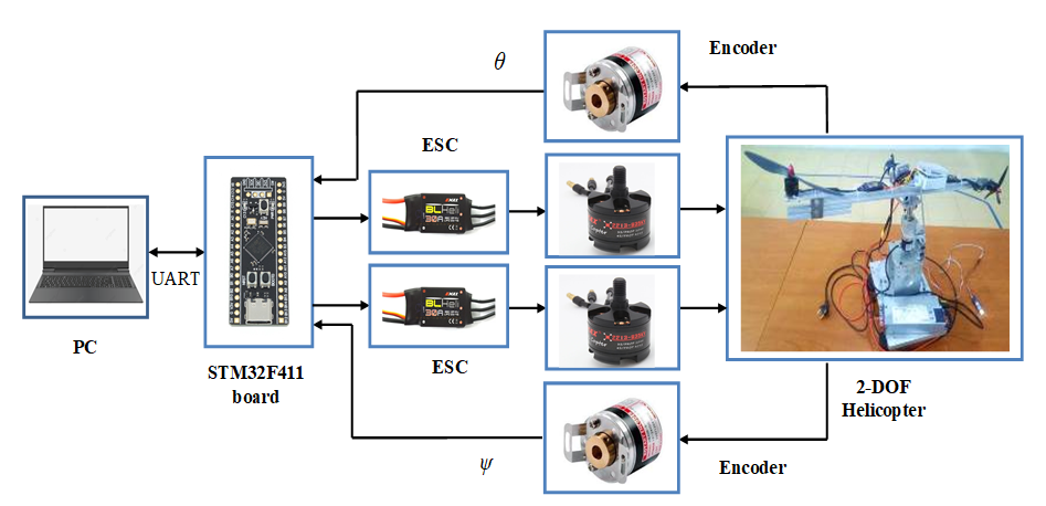
Figure 3. Block diagram of the experimental setup to validate the control law results
The system consists of a 2-DOF helicopter frame, two rotary encoders (AMC3808-001G, 500 P/R), two power amplifier circuits for controlling ESCs (EMAX BLHeli Series 30A), two BLDC motors (EMAX 2213), and a 12V 100A power supply (LITEON). An STM32F411 embedded board is used as the main controller of the system. The STM32F411 operates at a system frequency of up to 100 MHz and features a high-performance 32-bit CPU. Its wide range of peripheral interfaces enables not only efficient data processing but also facilitates the design of real-time embedded control systems. The control program is written in the C programming language using STM32CubeIDE. Experimental data are transmitted and displayed via UART communication at a baud rate of 9600.
The 2-DOF helicopter includes two BLDC motors (labeled 2 and 3), each equipped with a propeller mounted at opposite ends of the shaft along the pitch and yaw axes. These are attached to a pan-tilt frame (9). Two encoders (4 and 5) are mounted on the pitch and yaw axes of the frame to measure angular positions. The pan-tilt frame is rigidly mounted to the support bracket (1) via a motor flange coupling. The STM32F411 embedded board (7) receives feedback signals from the encoders and, based on the control algorithm described earlier, generates PPM pulse control signals to drive the BLDC motor drivers (6). The entire system is powered by a 12V DC source (8).
- Implementation of the Control Law Using the C Programming Language
In this section, we present the implementation of the control law on an embedded control system using the C programming language. To deploy the control law on the embedded platform (STM32F411 microcontroller), the aforementioned formulas are implemented using the following C code snippet:
- /* ----------------- control law program code --------------------*/
- float psi_theta_k = theta_k+beta_theta*theta_k1+theta_dk1;
- float psi_phi_k = phi_k+beta_phi*phi_k1+phi_dk1;
-
- float tau_p = (J_eq_p + m*l*l)*(theta_k1-(beta_theta+2)*theta_k-k_theta*theta_d-lambda_theta*psi_theta_k)/(delta_T*delta_T)+ m*g*l*cos(theta_k)+ B_p*(theta_k-theta_k1)/delta_T + m*g*l*l* sin(theta_k)*cos(theta_k)*(phi_k-phi_k1)*(phi_k-phi_k1)/(delta_T*delta_T);
- float tau_y = (J_eq_y + m*l*l*cos(theta_k)*cos(theta_k))*(phi_k1-(beta_phi+2)*phi_k-k_phi*phi_d-lambda_phi*psi_phi_k)/(delta_T*delta_T)+ B_p*(phi_k-phi_k1)/delta_T + m*g*l*l* sin(theta_k)*cos(theta_k)*(phi_k-phi_k1)*(theta_k-theta_k1)/(delta_T*delta_T);
- ;
- float A[2][2] = {{r_p*K_pp / (J_eq_p + m*l*l), K_py / (J_eq_p + m*l*l)},
- {K_yp / (J_eq_y + m*l*l*cos(theta_k)*cos(theta_k)), r_y*K_yy / (J_eq_y+ m*l*l*cos(theta_k)*cos(theta_k))}};
- float detA = A[0][0] * A[1][1] - A[0][1] * A[1][0];
- if (detA != 0)
- {
- float invA[2][2] = { {A[1][1] / detA, -A[0][1] / detA},
- {-A[1][0] / detA, A[0][0] / detA}};
-
- u_p = invA[0][0]*tau_p + invA[0][1]*tau_y;
- u_y = invA[1][0]*tau_p + invA[1][1]*tau_y;
- }
- else
- {
- }
|
- Experimental Scenarios
The structural parameters of the 2-DOF helicopter system are approximately identified based on the actual model, as shown in Table 1. The parameters of the proposed controller are selected experimentally through a trial-and-error process, with the following values:  = 0.006,
  = 0.6,
  = 1,
= 1,  = 0.02,
  = 0.4,
  = 1. The sampling time used in the embedded control program is = 0.02 seconds. Two experimental scenarios are designed as follows:
Table 1. System Parameters
Symbol | Parameter | Value | Unit |

| Equivalent moment of inertia around the pitch axis | 0.046 | kg·m2 |

| Equivalent moment of inertia around the yaw axis | 0.046 | kg·m2 |

| Mass of the helicopter body | 0.75 | kg |
| Viscous damping coefficient in the pitch direction | 0.01 | N/V |
| Viscous damping coefficient in the yaw direction | 0.01 | N/V |

| Distance from the system's center of mass to the mounting frame point | 0.04 | m |
| Pitch-axis torque constant generated by the pitch motor | 0.198 | N·m/V |
| Pitch-axis torque contribution from the yaw motor | -0.008 | N·m/V |
| Yaw-axis torque contribution from the pitch motor | -0.014 | N·m/V |
| Yaw-axis torque constant produced by the yaw motor | 0.056 | N·m/V |

| Acceleration due to gravity | 9.8 | m/s2 |
- Scenario 1: System Behavior Under External Disturbance
In this scenario, the helicopter system is held at its nominal equilibrium position and subjected to simulated external disturbances. These disturbances are introduced manually, following a predefined sequence: an upward force is applied along the pitch axis (positive direction), a forward force along the yaw axis (positive direction), and a combined disturbance in the negative direction for both axes simultaneously.
Figure 4 and Figure 5 illustrate the system’s dynamic response, showing the variations in the pitch angle ( ) and yaw angle (
 ) alongside the corresponding control signals and applied to the motors. A summary of key response characteristics is provided in Table 2, and Figure 6 includes a sequence of images capturing the physical behavior of the system during disturbance events.
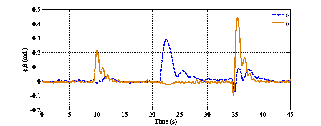
Figure 4. Pitch and yaw angle responses of the system under external disturbance
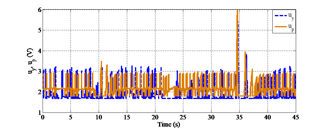
Figure 5. Control signals supplied to the pitch and yaw motors of the system under external disturbance
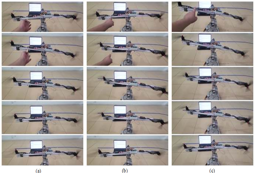
Figure 6. Illustrative images of the system’s response at moments of external disturbance: (a) around the 10th second; (b) around the 21rd second; (c) around the 34th second
Tabel 2. Response of proposed controllers in Scenario 1
Variable | Time (9-21 s) | Time (21-34 s) | Time (34-45 s) |
Pitch | Yaw | Pitch | Yaw | Pitch | Yaw |
Peak oscillation amplitude (rad.) | 0.213 | 0.031 | -0.022 | 0.3 | 0.443 | 0.09 |
Settling Time (s) | 3.5 | 3.0 | 2.7 | 8 | 4.5 | 6.0 |
Steady-state Error (rad.) | ±0.005 | ±0.005 | -0.005 | 0.01 | ±0.006 | ±0.003 |
From 0 to 10 seconds, the system remains in a stable state with minimal angular oscillations around the equilibrium position. However, noticeable disturbances occur at approximately 10 seconds, 21 seconds, and most significantly at 34 seconds, affecting both the pitch and yaw channels. Specifically, at around 10 seconds, the pitch angle spikes to approximately 0.2 rad. At about 21 seconds, the yaw angle increases sharply to around 0.3 rad. The most significant response is observed at approximately 34 seconds, when external disturbances drive both pitch and yaw angles down to -0.1 rad. The system immediately reacts by correcting the deviation, with θ peaking at nearly 0.45 rad and reaching up to 0.15 rad, before gradually returning to a stable state. Despite the presence of disturbances, the system in all scenarios rapidly returns to a stable state within approximately 3–5 seconds, demonstrating the controller’s fast and precise response capability. Corresponding to these responses, the control signals and clearly reflect the controller’s efforts to compensate for deviations and maintain trajectory tracking.
The control signal exhibits oscillation amplitudes ranging from 1.8 (V) to approximately 3.5 (V) and contains numerous high-frequency control pulses, which can be attributed to the relatively large quantization interval. At around 34 seconds, a significant control pulse appears in the pitch channel with an amplitude nearing 6 (V), coinciding with the peak deviation of θ. In contrast, the control signal remains relatively stable, fluctuating steadily within the range of 2–3 (V) without exhibiting large spikes. These results confirm that the control system effectively tracks the desired trajectory and promptly recovers from external disturbances.
- Scenario 2: System response when the setpoint values at the pitch and yaw axes change sequentially as follows:
The system begins at position A . At 11 seconds, it transitions to position
  , then moves to position
  after 20 seconds, and finally returns to the initial position A. The system responses are illustrated in Figure 7, Figure 8, Figure 9, and summarized in Table 3.
Figure 7 presents the time responses of the pitch angle and yaw angle of the 2-DOF helicopter system. The results indicate that the system responds distinctly to the reference changes occurring at approximately 11 s, 31 s, and 51 s. Specifically, at around 11 seconds, the pitch angle overshoots to more than 0.5 radians before rapidly settling to the target value of approximately  radians, while the yaw angle remains near zero. Similarly, at approximately 31 seconds, the yaw angle undergoes a significant step change, rising to nearly 0.4 radians before quickly converging to the steady-state value of , while the pitch angle remains nearly constant. At 51 seconds, both angles decrease sharply toward 0 radians, demonstrating the system's ability to return to the equilibrium state with accurate tracking performance.
Figure 8 displays the control voltage signals applied to the two motors responsible for controlling the pitch axis () and yaw axis (). The control signals exhibit a sensitive response to setpoint changes: at each transition point (11 s, 31 s, and 51 s), both and show sharp voltage spikes, corresponding to increased torque required for rapid angle adjustments. Following these initial spikes, the signals oscillate slightly around their respective average values, thereby maintaining system stability. Notably, the voltage peaks remain within the control limit (approximately 6 V), demonstrating that the controller operates effectively within a safe and constrained range.
Figure 9 illustrates the system’s trajectory as the setpoints move through positions A, B, and C, before returning to A. The simulation results confirm that the proposed control system can regulate the pitch and yaw angles accurately and rapidly, producing appropriate voltage responses without introducing significant oscillations after the transient phase. These findings validate the effectiveness of the control algorithm in stabilizing and guiding the 2-DOF helicopter system. However, in both experimental scenarios, the control signals at the equilibrium position exhibit pulse-like behavior, which may be attributed to the relatively large sampling period of 0.02 seconds used in the embedded control implementation.
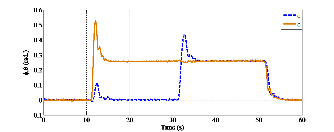
Figure 7. Response of the system’s pitch and yaw angles when the setpoint values change
Tabel 3. Response of proposed controllers in Scenario 2
Variable | Time (10-30 s) | Time (30-50 s) | Time (50-60 s) |
Pitch | Yaw | Pitch | Yaw | Pitch | Yaw |
Settling Time (s) | 3.2 | 2.8 | 2.2 | 4.0 | 3.5 | 3 |
Steady-state Error (rad.) | -0.002 | 0.0 | -0.002 | -0.002 | 0.001 | 0 |
Percent Overshoot (%) | 100 |
|
| 67 | 0 | 0 |
Peak oscillation amplitude (rad.) |
| 0.107 | -0.001 |
|
|
|
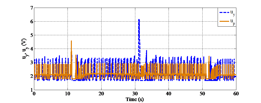
Figure 8. Control signals of the system when the setpoint values change
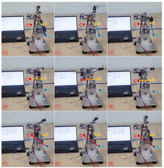
Figure 9. Illustration of the system's response to changes in setpoint values: (1)(2)(3) – Movement from A to B; (4)(5)(6) – Movement from B to C; (7)(8)(9) – Movement from C to A
- CONCLUSIONS
This study has introduced the development, deployment, and experimental assessment of a discrete-time synergetic controller tailored for a 2-DOF helicopter platform. The controller was implemented on an STM32-based embedded system, leveraging the synergetic control framework for its robustness in handling nonlinear behaviors, mitigating external disturbances, and accommodating parameter uncertainties. The method ensures stable system behavior and delivers rapid dynamic response in both stabilization and reference tracking scenarios. Experimental validation demonstrates that the proposed control scheme provides accurate regulation of both pitch and yaw movements. The system operates reliably in real-time conditions and exhibits low computational overhead, making it a viable option for embedded applications with limited processing resources. The integration on the STM32 microcontroller further confirms the practical feasibility of the approach in real-time embedded control environments. Prospective enhancements include the incorporation of high-resolution inertial sensors, the extension of the control framework to address higher-order discrete models, and the adoption of intelligent control paradigms such as fuzzy inference systems or neural network-based adaptation to better handle complex operating conditions. Additionally, refining the controller's sampling strategy and optimizing embedded code execution are expected to mitigate transient oscillations near steady-state conditions.
REFERENCES
- P. Castillo, R. Lozano, and A. E. Dzul. Modelling and control of mini-flying machines. Springer Science & Business Media. 2005. https://doi.org/10.1007/1-84628-179-2.
- G. V. Raffo, M. G. Ortega, and F. R. Rubio, “An integral predictive/nonlinear H∞ control structure for a quadrotor helicopter,” Automatica, vol. 46, no. 1, pp. 29–39, 2010, https://doi.org/10.1016/j.automatica.2009.10.018.
- G. Cai, B. M. Chen, X. Dong, and T. H. Lee, “Design and implementation of a robust and nonlinear flight control system for an unmanned helicopter,” Mechatronics, vol. 21, no. 5, pp. 803–820, 2011, https://doi.org/10.1016/j.mechatronics.2011.02.002.
- A. Fernández-Caballero, L. M. Belmonte, R. Morales, and J. A. Somolinos, “Generalized proportional integral control for an unmanned quadrotor system,” Int. J. Adv. Robot. Syst., vol. 12, no. 85, pp. 1–14, 2015, https://doi.org/10.5772/60833.
- S. M. Ahmad, A. J. Chipperfield, and M. O. Tokhi, “Parametric modelling and dynamic characterization of a two-degree-of-freedom twin-rotor multi-input multi-output system,” Proc. Inst. Mech. Eng. G, vol. 215, no. 2, pp. 63–78, 2001, https://doi.org/10.1243/0954410011531772.
- S. M. Ahmad, M. H. Shaheed, A. J. Chipperfield, and M. O. Tokhi, “Non-linear modelling of a one-degree-of-freedom twin-rotor multi-input multi-output system using radial basis function networks,” Proc. Inst. Mech. Eng. G, vol. 216, no. 4, pp. 197–208, 2002, https://doi.org/10.1243/09544100260369731.
- M. H. Shaheed, “Feedforward neural network based non-linear dynamic modelling of a TRMS using RPROP algorithm,” Aircraft Eng. Aerosp. Technol., vol. 77, no. 1, pp. 13–22, 2005, https://doi.org/10.1108/00022660510576000.
- A. Rahideh and M. H. Shaheed, “Mathematical dynamic modelling of a twin-rotor multiple input-multiple output system,” Proc. Inst. Mech. Eng. I, vol. 221, no. 1, pp. 89–101, 2007, https://doi.org/10.1243/09596518JSCE292.
- A. Rahideh, M. H. Shaheed, and H. J. C. Huijberts, “Dynamic modelling of a TRMS using analytical and empirical approaches,” Control Eng. Pract., vol. 16, no. 3, pp. 241–259, 2008, https://doi.org/10.1016/j.conengprac.2007.04.008.
- S. F. Toha and M. O. Tokhi, "ANFIS modelling of a twin rotor system using particle swarm optimisation and RLS," 2010 IEEE 9th International Conference on Cyberntic Intelligent Systems, pp. 1-6, 2010, https://doi.org/10.1109/UKRICIS.2010.5898130.
- A. Tastemirov, A. Lecchini-Visintini, and R. M. Morales, “Complete dynamic model of a twin rotor MIMO System (TRMS) with experimental validation,” Control Engineering Practice, 66, 89-98, 2017, https://doi.org/10.1016/j.conengprac.2017.06.009.
- S. M. Ahmad, A. J. Chipperfield, and M. O. Tokhi, “Dynamic modelling and open-loop control of a twin rotor multi-input multi-output system,” Proc. Inst. Mech. Eng. I, vol. 216, no. 6, pp. 477–496, 2002, https://doi.org/10.1177/095965180221600604.
- S. M. Ahmad, A. J. Chipperfield, and M. O. Tokhi, “Dynamic modelling and linear quadratic Gaussian control of a twin-rotor multi-input multi-output system,” Proc. Inst. Mech. Eng. I, vol. 217, no. 3, pp. 203–227, 2003, https://doi.org/10.1177/095965180321700304.
- M. López-Martínez, M. G. Ortega, C. Vivas, and F. R. Rubio, “Nonlinear L2 control of a laboratory helicopter with variable speed rotors,” Automatica, vol. 43, no. 4, pp. 655–661, 2007, https://doi.org/10.1016/j.automatica.2006.10.013.
- A. Rahideh, A. H. Bajodah, and M. H. Shaheed, “Real time adaptive nonlinear model inversion control of a twin rotor MIMO system using neural networks,” Eng. Appl. Artif. Intell., vol. 25, no. 6, pp. 1289–1297, 2012, https://doi.org/10.1016/j.engappai.2011.12.006.
- G. Reynoso-Meza, S. Garcia-Nieto, J. Sanchis, and F. X. Blasco, “Controller tuning by means of multi-objective optimization algorithms: a global tuning framework,” IEEE Trans. Control Syst. Technol., vol. 21, no. 2, pp. 445–458, 2013, https://doi.org/10.1109/TCST.2012.2185698.
- C. Lebres, V. Santos, N. F. Ferreira, and J. T. Machado, “Application of fractional controllers for quad rotor,” Nonlinear Science and Complexity, pp. 303-309, 2011, https://doi.org/10.1007/978-90-481-9884-9_35.
- A. Boubakir, S. Labiod, F. Boudjema, and F. Plestan, “Design and experimentation of a self-tuning PID control applied to the 3DOF helicopter,” Arch. Control Sci., vol. 23, no. 3, pp. 311–331, 2013, https://doi.org/10.2478/acsc-2013-0019.
- J.-G. Juang, M.-T. Huang, and W.-K. Liu, “PID control using presearched genetic algorithms for a MIMO system,” IEEE Trans. Syst., Man, Cybern. C, vol. 38, no. 5, pp. 716–727, 2008, https://doi.org/10.1109/TSMCC.2008.923890.
- A. Muhammad, A. Omar, and M. Ali, “Model-Free LQR Based PID Controller for Trajectory Tracking of 2-DoF Helicopter: Comparison and Experimental Results,” arXiv preprint arXiv:2103.10988, 2021, https://doi.org/10.48550/arXiv.2103.10988.
- F. Gopmandal and A. Ghosh, “LQR-based MIMO PID control of a 2-DOF helicopter system with uncertain cross-coupled gain,” IFAC-PapersOnLine, vol. 55, no. 22, pp. 183–188, 2022, https://doi.org/10.1016/j.ifacol.2023.03.031.
- S. K. Pandey and V. Laxmi, “Optimal control of twin rotor MIMO system using LQR technique,” in Int. Conf. Comput. Intell. Data Min., pp. 11–21, 2014, https://doi.org/10.1007/978-81-322-2205-7_2.
- C. W. Tao, J. S. Taur, and Y. C. Chen, “Design of a parallel distributed fuzzy LQR controller for the twin rotor multi-input multi-output system,” Fuzzy Sets Syst., vol. 161, no. 15, pp. 2081–2103, 2010, https://doi.org/10.1016/j.fss.2009.12.007.
- E. V. Kumar, G. S. Raaja, and J. Jerome, “Adaptive PSO for optimal LQR tracking control of 2 DOF laboratory helicopter,” Appl. Soft Comput., vol. 41, pp. 77–90, 2016, https://doi.org/10.1016/j.asoc.2015.12.023.
- R. G. Subramanian and V. K. Elumalai, “Robust MRAC augmented baseline LQR for tracking control of 2 DoF helicopter,” Robot. Auton. Syst., vol. 86, pp. 70–77, 2016, https://doi.org/10.1016/j.robot.2016.08.004.
- S. Butt and H. Aschemann, “Control design by extended linearisation techniques for a two degrees of freedom helicopter,” IFAC-PapersOnLine, vol. 48, no. 12, pp. 302–307, 2015, https://doi.org/10.1016/j.ifacol.2015.09.274.
- B. Luo, H. N. Wu, and T. Huang, “Optimal output regulation for model-free Quanser helicopter with multistep Q-learning,” IEEE Trans. Ind. Electron., vol. 65, no. 10, pp. 8293–8302, 2018, https://doi.org/10.1109/TIE.2017.2784354.
- A. P. S. Ramalakshmi, P. S. Manoharan, K. Harshath, and M. Varatharajan, “Model predictive control of 2DOF helicopter,” Int. J. Innov. Sci. Res., vol. 24, no. 2, pp. 337–346, 2016, https://doi.org/10.1109/ICEEE2019.2019.00068.
- D. K. Saroj, I. Kar and V. K. Pandey, "Sliding mode controller design for Twin Rotor MIMO system with a nonlinear state observer," 2013 International Mutli-Conference on Automation, Computing, Communication, Control and Compressed Sensing (iMac4s), pp. 668-673, 2013, https://doi.org/10.1109/iMac4s.2013.6526493.
- A. K. Ekbote, N. S. Srinivasan, and A. D. Mahindrakar, “Terminal sliding mode control of a twin rotor multiple-input multiple-output system,” IFAC Proc. Volumes, vol. 44, no. 1, pp. 10952–10957, 2011, https://doi.org/10.3182/20110828-6-IT-1002.00645.
- M. Ilyas, N. Abbas, M. UbaidUllah, W. A. Imtiaz, M. A. Q. Shah, and K. Mahmood, “Control Law Design for Twin Rotor MIMO System with Nonlinear Control Strategy,” Discrete Dynamics in Nature and Society, vol. 2016, no. 1, p. 2952738, 2016, https://doi.org/10.1155/2016/2952738.
- M. Derakhshannia, S. B. F. Asl and S. S. Moosapour, "Backstepping Terminal Sliding Mode Control Design for a TRMS," 2021 7th International Conference on Control, Instrumentation and Automation (ICCIA), pp. 1-5, 2021, https://doi.org/10.1109/ICCIA52082.2021.9403545.
- A. Boulkroune, M. M’Saad, and H. Chekireb, “Design of a fuzzy adaptive controller for MIMO nonlinear time-delay systems with unknown actuator nonlinearities and unknown control direction,” Information Sciences, vol. 180, no. 24, pp. 5041–5059, 2010, https://doi.org/10.1016/j.ins.2010.08.034.
- B. Wu, J. Wu, J. Zhang, G. Tang, and Z. Zhao, “Adaptive Neural Control of a 2DOF Helicopter with Input Saturation and Time-Varying Output Constraint,” Actuators, vol. 11, no. 336, 2022, https://doi.org/10.3390/act11110336.
- J. M. Frasik and S. I. L. Gabrielsen. Practical application of advanced control: An evaluation of control methods on a quanser aero (Master's thesis, Universitetet i Agder; University of Agder). 2018. http://hdl.handle.net/11250/2563895.
- R. Patel, D. Deb, H. Modi, and S. Shah, “Adaptive backstepping control scheme with integral action for quanser 2-DOF helicopter,” in Proc. Int. Conf. Advances in Computing, Communications and Informatics (ICACCI), 2017, https://doi.org/10.1109/ICACCI.2017.8125901.
- S. M. Schlanbusch and J. Zhou, "Adaptive Backstepping Control of a 2-DOF Helicopter System with Uniform Quantized Inputs," IECON 2020 The 46th Annual Conference of the IEEE Industrial Electronics Society, pp. 88-94, 2020. https://doi.org/10.1109/IECON43393.2020.9254497.
- S. Mondal and C. Mahanta, “Adaptive second-order sliding mode controller for a twin rotor multi-input–multi-output system,” IET Control Theory & Applications, vol. 6, no. 14, pp. 2157–2167, 2012, https://doi.org/10.1049/iet-cta.2011.0478.
- Y. Zhang, C. Yang, and J. Qiu, “Neural Network-Based Adaptive Finite-Time Control for 2-DOF Helicopter Systems With Prescribed Performance and Input Saturation,” J. Intell. Robot. Syst., vol. 110, no. 55, 2024, https://doi.org/10.1007/s10846-024-02165-5.
- G. Ma, H. Wu, Z. Zhao, T. Zou, and K. S. Hong, “Adaptive neural network control of a non‐linear two‐degree‐of‐freedom helicopter system with prescribed performance,” IET Control Theory & Applications, vol. 17, no. 13, pp. 1789-1799, 2023, https://doi.org/10.1049/cth2.12379.
- L. Cao, J. Zhang, S. Liu, and Z. Zhao, “Adaptive neural fault‐tolerant control of an uncertain 2‐DOF helicopter system with actuator faults and output error constrains,” IET Control Theory & Applications, vol. 17, no. 13, pp. 1768-1778, 2023, https://doi.org/10.1049/cth2.12347.
- F. Silva and M. Correia, “Robust Position Regulation of a 2-DOF Experimental Helicopter Using Higher Order Super Twisting Sliding Mode Control,” Stud. Eng. Exact Sci., vol. 11, no. 2, pp. 1–17, 2023, https://doi.org/10.54021/seesv5n2-236.
- J. Li and C. ZHU, “LPV sliding mode observer and control design for a 2-DOF helicopter system,” 2021, https://www.politesi.polimi.it/handle/10589/198254.
- B. M. Kim and S. J. Yoo, “Approximation-Based Quantized State Feedback Tracking of Uncertain Input-Saturated MIMO Nonlinear Systems with Application to 2-DOF Helicopter,” Mathematics, vol. 9, no. 1062, 2021, https://doi.org/10.3390/math9091062.
- M. Reyhanoglu, M. Jafari, and M. Rehan, “Simple Learning-Based Robust Trajectory Tracking Control of a 2-DOF Helicopter System,” Electronics, vol. 11, no. 2075, 2022, https://doi.org/10.3390/electronics11132075.
- S. I. Abdelmaksoud, M. Mailah, and A. M. Abdallah, “Practical real-time implementation of a disturbance rejection control scheme for a twin-rotor helicopter system using intelligent active force control,” IEEE Access, vol. 9, pp. 4886–4901, 2020, https://doi.org/10.1109/ACCESS.2020.3046728.
- R. C. Romana, R. E. Precupa, and R. C. David, “Second Order Intelligent Proportional-Integral Fuzzy Control of Twin Rotor Aerodynamic Systems,” Procedia Comput. Sci., vol. 139, pp. 372–380, 2018, https://doi.org/10.1016/j.procs.2018.10.277.
- E. C. V. González, D. M. Rivera and E. J. Gómez, "Model and Observer-Based Controller Design for a Quanser Helicopter with Two DOF," 2012 IEEE Ninth Electronics, Robotics and Automotive Mechanics Conference, pp. 267-271, 2012. https://doi.org/10.1109/CERMA.2012.50.
- G. G. Neto, F. dos Santos Barbosa and B. A. Angélico, "2-DOF helicopter controlling by pole-placements," 2016 12th IEEE International Conference on Industry Applications (INDUSCON), pp. 1-5, 2016, https://doi.org/10.1109/INDUSCON.2016.7874535.
- P. Wen and Y. Li, "Twin rotor system modeling, de-coupling and optimal control," 2011 IEEE International Conference on Mechatronics and Automation, Beijing, China, 2011, pp. 1839-1842, 2011, https://doi.org/10.1109/ICMA.2011.5986259.
- A. Tastemirov, A. Lecchini-Visintini, and R. M. Morales, “Complete dynamic model of a twin rotor MIMO System (TRMS) with experimental validation,” Control Eng. Pract., vol. 66, pp. 89–98, 2017, https://doi.org/10.1016/j.conengprac.2017.06.009.
- A. Rahideh, M. H. Shaheed, and H. J. C. Huijberts, “Dynamic modelling of a TRMS using analytical and empirical approaches,” Control Eng. Pract., vol. 16, no. 3, pp. 241–259, 2008, https://doi.org/10.1016/j.conengprac.2007.04.008.
- S. M. Ahmad, A. J. Chipperfield, and M. O. Tokhi, “Dynamic modelling and linear quadratic Gaussian control of a twin-rotor multi-input multi-output system,” Proc. Inst. Mech. Eng. Part I: J. Syst. Control Eng., vol. 217, no. 3, pp. 203–227, 2003, https://doi.org/10.1243/095965103765832885.
- C. Nguyen, H. Phan, and H. Nguyen, “An energy saving method of stable control of inverted pendulum system when affected by external interference using auxiliary pendulum,” E3S Web Conf., vol. 104, p. 01015, 2019, https://doi.org/10.1051/e3sconf/201910401015.
- A. O. Muhammad, A. S. Omar, and H. A. Habib, “Simple Learning-Based Robust Trajectory Tracking Control of a 2-DOF Helicopter System,” Electronics, vol. 11, no. 13, p. 2075, 2022, https://doi.org/10.3390/electronics11132075.
- N. X. Chiem, “Synthesis of an Orbit Tracking Controller for a 2DOF Helicopter based on Sequential Manifolds with Stabilization Time in the Presence of Disturbances,” Engineering, Technology & Applied Science Research, vol. 14, no. 4, pp. 15083-15089, 2023, https://doi.org/10.48084/etasr.7512.
- H. Xu, C. Wang, and Z. Li, “Adaptive Fault-Tolerant Control of a Nonlinear 2-DOF Helicopter System With Prescribed Performance,” IET Control Theory & Applications, vol. 18, no. 5, pp. 623–634, 2024, https://doi.org/10.1049/cth2.12679.
- J. Jacob and N. Khaneja, “A General Controller Scheme for Stabilization & Disturbance Rejection with Application to Non-Linear Systems and its Implementation on 2 DOF Helicopter,” arXiv preprint arXiv:2107.03117, 2021, https://doi.org/10.48550/arXiv.2107.03117.
- A. K. Hamoudi and S. S. Husain, “Design of Adaptive Synergetic Controller for One-Degree of Freedom Robotic ARM Under External Disturbance,” Journal of Robotics and Control (JRC), vol. 6, no. 1, 2025, https://doi.org/10.18196/jrc.v6i1.25207.
- M. Q. Kadhim, F. R. Yaseen, H. Al-Khazraji, and A. J. Humaidi, “Application of Terminal Synergetic Control Based Water Strider Optimizer for Magnetic Bearing Systems,” Journal of Robotics and Control (JRC), vol. 5, no. 6, pp. 1973–1979, 2024, https://doi.org/10.18196/jrc.v5i6.23867.
- A. K. Abbas and S. K. Kadhim, “Dynamic Motion Control of Two-Link Robots with Adaptive Synergetic Algorithms,” Journal of Robotics and Control (JRC), vol. 5, no. 5, pp. 1536–1548, 2024, https://doi.org/10.18196/jrc.v5i5.22985.
- H. Al-Khazraji, K. Al-Badri, R. Al-Majeez, and A. J. Humaidi, “Synergetic Control Design Based Sparrow Search Optimization for Tracking Control of Driven-Pendulum System,” Journal of Robotics and Control (JRC), vol. 5, no. 5, pp. 1549–1556, 2024, https://doi.org/10.18196/jrc.v5i5.22893.
- A. S. Ahmed and S. K. Kadhim, “A Comparative Study Between Convolution and Optimal Backstepping Controller for Single Arm Pneumatic Artificial Muscles,” Journal of Robotics and Control (JRC), vol. 3, no. 6, pp. 769–778, 2022, https://doi.org/10.18196/jrc.v3i6.16064.
- H. Al-Khazraji, “Optimal Synergetic and Feedback Linearization Controllers Design for Magnetic Levitation System,” Journal of Robotics and Control (JRC), vol. 6, no. 1, pp. 22–30, 2024, https://doi.org/10.18196/jrc.v6i1.24452.
- A. J. Humaidi and H. Al-Khazraji, “Integration of Sparrow Search Optimization with Terminal Synergetic Control for Permanent Magnet Linear Synchronous Motors,” Journal of Robotics and Control (JRC), vol. 6, no. 2, pp. 123–130, 2025, https://doi.org/10.18196/jrc.v6i2.26174.
- O. Y. Ismael, M. N. Noaman, and I. Kh. Abdullah, “Fick’s Law Algorithm Based-Nonlinear Model Predictive Control of Twin Rotor MIMO System,” Journal of Robotics and Control (JRC), vol. 5, no. 3, pp. 694–705, 2024, https://doi.org/10.18196/jrc.v5i1.20615.
- M. Qasim, M. N. Noaman, and O. Y. Ismael, “Tracking Iterative Learning Control of TRMS using Feedback Linearization Model with Input Disturbance,” Journal of Robotics and Control (JRC), vol. 6, no. 1, pp. 1–10, 2025, https://doi.org/10.18196/jrc.v6i1.25579.
- R. Al-Majeez, K. Al-Badri, H. Al-Khazraji, and S. Ra'afat, “Design of A Backstepping Control and Synergetic Control for An Interconnected Twin-Tanks System: A Comparative Study,” International Journal of Robotics and Control Systems, vol. 4, no. 4, pp. 2041–2054, 2024, https://doi.org/10.31763/ijrcs.v4i4.1682.
- H. Al-Khazraji, K. Albadri, R. Almajeez, and A. Humaidi, “Synergetic Control-Based Sea Lion Optimization Approach for Position Tracking Control of Ball and Beam System,” International Journal of Robotics and Control Systems, vol. 4, no. 4, pp. 1547–1560, 2024, https://doi.org/10.31763/ijrcs.v4i4.1551.
- N. X. Chiem, B. X. Hai, and T. C. Phan, “Synthesis of Adaptive Sliding Mode Control for Twin Rotor MIMO System with Mass Uncertainty based on Synergetic Control Theory,” International Journal of Robotics and Control Systems, vol. 4, no. 1, pp. 174–187, 2024, https://doi.org/10.31763/ijrcs.v4i1.1307.
- N. X. Chiem and L. T. Thang, “Synthesis of an Orbit Tracking Controller for a 2DOF Helicopter based on Sequential Manifolds with Stabilization Time in the Presence of Disturbances,” Engineering, Technology & Applied Science Research, vol. 14, no. 4, pp. 15083–15089, 2024, https://doi.org/10.48084/etasr.7512.
- A. A. Kolesnikov, "Introduction of synergetic control," 2014 American Control Conference, pp. 3013-3016, 2014, https://doi.org/10.1109/ACC.2014.6859397.
- A. A. Kolesnikov and A. A. Kuz’menko, “Sliding Mode Control Laws Design by the ADAR Method with Subsequent Invariant Manifolds Aggregation,” Mekhatronika, Avtomatizatsiya, Upravlenie, vol. 20, no. 8, pp. 451–460, 2019, https://doi.org/10.17587/mau.20.451-460.
- A. A. Kolesnikov and A. S. Mushenko, "Applied Theory of Nonlinear System Design: Method Comparison," 2019 III International Conference on Control in Technical Systems (CTS), pp. 50-53, 2019. https://doi.org/10.1109/CTS48763.2019.8973304.
- A. A. Kolesnikov and A. A. Kuz’menko, "Forced Sliding Mode Control: Synergetic Approach," 2020 2nd International Conference on Control Systems, Mathematical Modeling, Automation and Energy Efficiency (SUMMA), pp. 36-40, 2020, https://doi.org/10.1109/SUMMA50634.2020.9280620.
- E. Obukhova, G. E. Veselov, P. Obukhov, A. Beskopylny, S. A. Stel’makh, and E. M. Shcherban’, “Synergetic Synthesis of Nonlinear Laws of Throttle Control of a Pneumatic Drive,” Appl. Sci., vol. 12, no. 4, 2022, https://doi.org/10.3390/app12041797.
- A. A. Kuz’menko, “Robust Control of Permanent Magnet Synchronous Motor: Synergetic Approach,” Mekhatronika, Avtomatizatsiya, Upravlenie, vol. 21, no. 8, pp. 480–488, 2020, https://doi.org/10.17587/mau.21.480-488.
- C. X. Nguyen, A. D. Lukianov, T. D. Pham, and A. D. Nguyen, “Synthesis of a nonlinear control law with efficiency energy for the self-balancing two wheeled vehicle,” IOP Conf. Ser.: Mater. Sci. Eng., vol. 900, 2020, https://doi.org/10.1088/1757-899X/900/1/012002.
- C. X. Nguyen et al., “Synthesis of non-linear controller to energy efficiency for damped-elastic-jointed inverted pendulum,” E3S Web Conf., vol. 279, p. 01020, 2021, https://doi.org/10.1051/e3sconf/202127901020.
- Ph. C. Tran et al., “Design control system for Pan-Tilt Camera for Visual Tracking based on ADAR method taking into account energy output,” E3S Web Conf., vol. 279, p. 01007, 2021, https://doi.org/10.1051/e3sconf/202127902007.
- L. T. Thang, T. V. Son, T. D. Khoa, and N. X. Chiem, “Synthesis of sliding mode control for flexible-joint manipulators based on serial invariant manifolds,” Bull. Electr. Eng. Inform., vol. 12, no. 1, pp. 98–108, 2023, https://doi.org/10.11591/eei.v12i1.4363.
- C. N. Xuan and L. T. Thang, "Design of nonlinear controller based on ADAR method for wedge balancing," 2022 22nd International Conference on Control, Automation and Systems (ICCAS), pp. 1372-1377, 2022, https://doi.org/10.23919/ICCAS55662.2022.10003732.
- N. X. Chiem and L. T. Thang, “Synthesis of inverted wedge-balanced stable nonlinear controller based on synergetic control theory,” in Proc. XVII Int. Sci.-Tech. Conf. “Dynamics of Technical Systems” (DTS-2021), AIP Conf. Proc., vol. 2507, no. 1, 2023, https://doi.org/10.1063/5.0109852.
- C. X. Nguyen, S. V. Tran, and H. N. Phan, “Control Law Synthesis for Flexible Joint Manipulator Based on Synergetic Control Theory,” Mekhatronika, Avtomatizatsiya, Upravlenie, vol. 24, no. 8, pp. 395–402, 2023, https://doi.org/10.17587/mau.24.395-402.
- N. X. Chiem, L. T. Thang and N. C. Dinh, "Synthesis of stable control law for ball and beam system robust to disturbances based on synergetic control theory," 2023 12th International Conference on Control, Automation and Information Sciences (ICCAIS), pp. 466-470, 2023, https://doi.org/10.1109/ICCAIS59597.2023.10382309.
- Nguyen X.C., Le D.T. “Adaptive finite-time synergetic control for flexible-joint robot manipulator with disturbance inputs,” Electrical Engineering & Electromechanics, vol. 3, pp. 45-52, 2025, https://doi.org/10.20998/2074-272X.2025.3.07.
- C. N. X. Chiem and T. P. Xuan, “Synthesis of control laws for magnetic levitation systems based on serial invariant manifolds,” IAES Int. J. Robot. Autom. (IJRA), vol. 11, no. 4, pp. 333–342, 2022, https://doi.org/10.11591/ijra.v11i4.pp333-342.
- N. X. Chiem, “Cascade control for trajectory-tracking mobile robots based on synergetic control theory and Lyapunov functions,” Control Syst. Optim. Lett., vol. 3, no. 1, 2025, https://doi.org/10.59247/csol.v3i1.169.
- M. Poovizhi, M. S. Kumaran, P. Ragul, L. I. Priyadarshini and R. Logambal, "Investigation of mathematical modelling of brushless dc motor(BLDC) drives by using MATLAB-SIMULINK," 2017 International Conference on Power and Embedded Drive Control (ICPEDC), pp. 178-183, 2017, https://doi.org/10.1109/ICPEDC.2017.8081083.
- J. Tripathi, K. Sharma, and J. N. Rai, “Speed Control Analysis of Brushless DC Motor Using PI, PID and Fuzzy-PI Controllers,” Int. J. Electr. Electron. Res., vol. 10, no. 3, pp. 470-474, 2022, https://doi.org/10.37391/ijeer.100311.
AUTHOR BIOGRAPHY

| Nguyen Xuan Chiem received a Ph.D. degree in Technology and equipment for mechanical and physical-technical processing from Don State Technical University, Russia in 2012. From 2013 to the present, he is a lecturer at the Department of Automation and Computing Techniques, Institute of Control Engineering, Le Quy Don Technical University. His research interests include nonlinear control, intelligent control, and embedded systems. |
|
|

| Pham Duy Thai received his PhD in Information Technology from Moscow State University of Information Technology, Radio Engineering and Electronics in 2015. Since 2016, he has been a lecturer at the Department of Biomedical Electronics, Institute of Control Engineering, Le Quy Don University of Technology. His research interests include information systems, information technology and databases. |
|
|

| Tran Cong Phan born in 1983, received his Master of Engineering in Flight Control Equipment, Bauman Moscow State Technical University, Moscow, Russia, 2009. From 2010 to the present, he is a lecturer at the Department of Automation and Computing Techniques, Institute of Control Engineering, Le Quy Don Technical University. His research interests include automatic control theory, intelligent control, and computer science. |
|
|

| Bùi Xuan Hai born in 1995, received his Bachelor of Engineering in Control and Automation Engineering (advanced program in control and informatics in engineering systems) from Le Quy Don University, Vietnam in 2019. From 2023 to present, he has been studying for a master's degree in control and automation engineering at Le Quy Don University of Technology. His main research interests are nonlinear control, intelligent control, and digital image processing. |
Implementation of a Synergetic Controller for a 2-DOF Helicopter on an Embedded Platform Using an STM32 Microcontroller (Nguyen Xuan Chiem)