ISSN: 2685-9572 Buletin Ilmiah Sarjana Teknik Elektro
Induction Motor Speed Control Using PID Tuned by Particle Swarm Optimization Under Vector Control
Hari Maghfiroh 1, Meiyanto Eko Sulistyo 1, Alfian Ma’arif 2, Nia Maharani Raharja 3,
Iswanto Suwarno 4, Dwi Ana Ratna Wati 5, Muhammad Ahmad Baballe 6
1 Dept. of Electrical Engineering, Universitas Sebelas Maret, Indonesia
2 Dept. of Electrical Engineering, Universitas Ahmad Dahlan, Indonesia
3 Universitas Islam Negeri Sunan Kalijaga, Yogyakarta, Indonesia
4 Dept. of Electrical Engineering, Universitas Muhammadiyah Yogyakarta, Indonesia
5 Dept. of Electrical Engineering, Universitas Islam Indonesia, Indonesia
6 Dept. of Mechatronic Engineering, Nigerian Defence Academy (NDA), Kaduna, Nigeria
ARTICLE INFORMATION |
| ABSTRACT |
Article History: Received 28 March 2025 Revised 07 May 2025 Accepted 17 May 2025 |
| 
Induction motors (IMs) are widely used in industrial applications due to their cost-effectiveness, durability, and low maintenance requirements. This study investigates the speed control of an induction motor using vector control combined with a PID controller whose parameters are tuned via Particle Swarm Optimization (PID-PSO). A reduced-order small-signal state-space model is derived from a detailed nonlinear IM model to facilitate efficient controller tuning while maintaining fidelity to real-world behavior. The PID parameters are optimized using PSO, with the Integral of Absolute Error (IAE) selected as the objective function due to its ability to penalize long-duration deviations and reflect steady-state performance. The optimized PID controller is then validated on the full nonlinear IM model under speed and load variations. Simulation results demonstrate that PID-PSO significantly outperforms manually tuned PID control in terms of tracking accuracy, reducing IAE by 37.79% and 14.76% under speed and load variation conditions, respectively. However, this improvement comes at the cost of slightly slower settling time. These results highlight a trade-off between accuracy and transient response, motivating future research on multi-objective optimization to balance conflicting criteria such as robustness, energy efficiency, and response time. |
Keywords: Induction Motor; Speed Control; PID Tuning; PSO; Optimal Tuning |
Corresponding Author: Hari Maghfiroh, Department of Electrical Engineering, Universitas Sebelas Maret, Indonesia. Email: hari.maghfiroh@staff.uns.ac.id |
This work is open access under a Creative Commons Attribution-Share Alike 4.0 
|
Document Citation: H. Maghfiroh, M. E. Sulistyo, A. Ma’arif, N. M. Raharja, I. Suwarno, D. A. R. Wati, and M. A. Baballe, “Induction Motor Speed Control Using PID Tuned by Particle Swarm Optimization Under Vector Control,” Buletin Ilmiah Sarjana Teknik Elektro, vol. 7, no. 2, pp. 172-180, 2025, DOI: 10.12928/biste.v7i2.13112. |
- INTRODUCTION
The electric motor is the backbone of modern industry due to its ability to enhance process efficiency [1]–[3]. Electric motors are broadly classified based on their supply current into AC and DC types. AC motors are more favorable in terms of maintenance costs compared to DC motors, which require carbon brushes [4]. AC motors are further divided into synchronous and asynchronous types. The induction motor (IM), a subtype of asynchronous motor, is the most widely used due to its low cost, simple yet robust design, ease of maintenance, and high reliability [5][6]. In fact, IMs account for approximately 60% of a plant’s total energy consumption [7]. They are also commonly used as traction motors in electric vehicles, such as those discussed in [8]–[11], and in railway applications [12].
Despite their widespread use, induction motors present challenges due to their complex and nonlinear mathematical behavior and lack of inherent speed control, making them traditionally suited for fixed-speed applications [13]. According to [14], the main limitation of IMs is their speed control capability. However, with advances in semiconductor technology, more sophisticated real-time control methods have become feasible.
One widely adopted technique for IM speed regulation is the Variable Frequency Drive (VFD). An overview of VFD control approaches is shown in Figure 1 [15]. VFDs are generally classified as either sensor-based or sensorless. The sensor-based category is further subdivided into scalar and vector control methods. Scalar control offers simple modeling and is parameter independent [16]. In contrast, vector control is more commonly used due to its superior performance [17]. Vector control includes two main techniques: field-oriented control (FOC) and direct torque control (DTC). FOC provides fast dynamic response and high efficiency, but is highly sensitive to parameter variations. DTC offers robust performance even under parameter fluctuations [18].
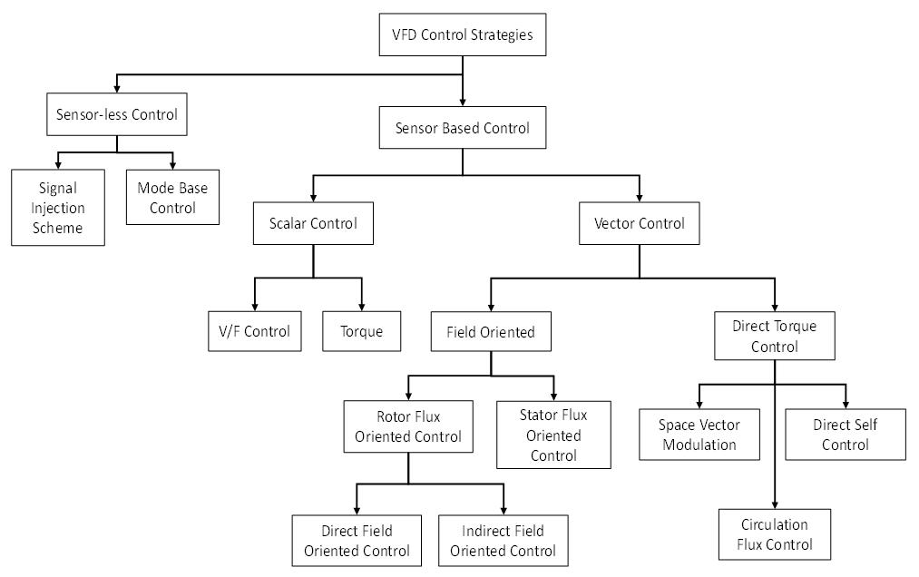
Figure 1. VFD control classification [15]
While FOC and DTC effectively manage torque, they do not directly handle speed regulation, necessitating additional control mechanisms. Numerous algorithms have been developed for IM speed control, including Proportional–Integral–Derivative (PID) [4],[19], Linear Quadratic Gaussian (LQG) [20], Sliding Mode Control (SMC) [21][22], Artificial Neural Networks (ANN) [23][24], Fuzzy Logic Controller (FLC) [25], and hybrid approaches that combine traditional and intelligent techniques [26]. Among these, PID control remains the most widely used due to its simplicity and robust general performance [27][28]. As noted in [29][30], PID is easily applicable across a wide range of industrial systems.
According to [31], nearly 90% of industries utilize PID controllers. The Ziegler–Nichols method is one of the most well-known PID tuning techniques. However, achieving optimal performance using this method can be difficult [32]. To overcome this, researchers have employed metaheuristic optimization algorithms such as Ant Colony Optimization (ACO) [33], Genetic Algorithms (GA) [34], and Particle Swarm Optimization (PSO) [35] to fine-tune PID gains.
In this study, PSO is used to optimize PID parameters based on a defined objective function. PSO has been demonstrated to be effective in obtaining optimal control gains in various domains, as shown in [36][37]. Its fast convergence and ease of implementation have made it a popular choice for control tasks involving DC motors, robotic manipulators, and intelligent wheelchairs [38].
The main contributions of this paper are as follows:
- It presents a simplified control design methodology by leveraging a small-signal state-space model derived from a detailed IM;
- It demonstrates the effectiveness of PSO-tuned PID in improving steady-state performance using the Integral of Absolute Error (IAE) as the optimization criterion;
- It compares the proposed method against a conventional PID controller under varying speed and load scenarios, showing significant error reduction without compromising transient stability.
This work aims to provide a computationally efficient yet effective tuning strategy for vector-controlled IMs, paving the way for future research into multi-objective optimization techniques that simultaneously consider robustness, energy efficiency, and transient performance. The remainder of this paper is organized as follows: Section II presents the IM modeling and the PSO algorithm used for PID tuning. Section III discusses the results and analysis. Section IV concludes the paper.
- METHODS
System Model
The IM specifications used in this study are listed in Table 1. The detailed Simulink model of the IM system is illustrated in Figure 2, which includes both vector control and speed control blocks. This work focuses on optimizing the speed control component, while the vector control is based on the FOC method. However, performing PID optimization directly on the full detailed model (Figure 2) is computationally intensive and not practical for real-time or hardware applications. Therefore, a simplified state-space model is derived to enable efficient controller tuning. This reduced-order model provides a practical interface for offline PID tuning, which can later be implemented on real hardware systems.
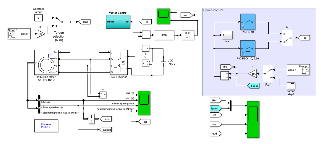
Figure 2. Induction motor detailed model in Simulink
Table 1. Induction motor parameters
Parameters | Values |
Power | 50 HP |
Torque | 300 Nm |
Nominal Voltage | 460 V |
Nominal Frequency | 60 Hz |
Rotor type | Squirrel-cage |
To approximate the system behavior, black-box modeling is employed using MATLAB's System Identification Toolbox. This approach extracts a state-space model from input-output data of the Simulink simulation. Unlike analytical or physics-based derivation (e.g., [39][40]), this method requires no prior knowledge of motor parameters, making it suitable for real-world hardware where parameters may be unknown or difficult to measure [41]. The resulting state-space representation is given in (1), where  ,
,  , and
, and  denote the state, input, and output vectors, respectively:
| 
| (1) |
| 
|
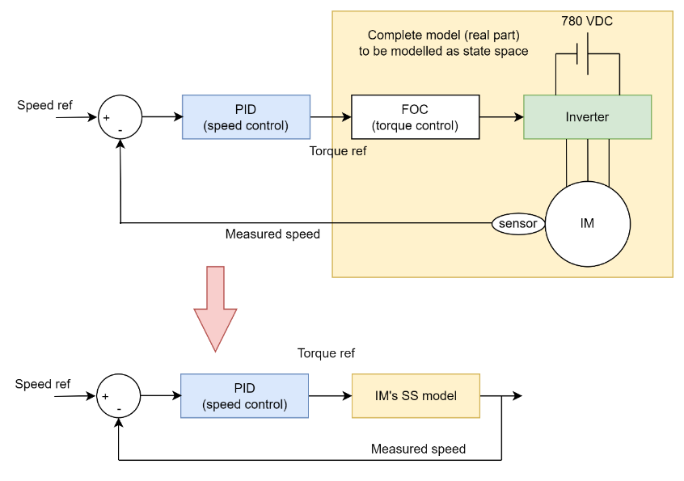
The modeling process is summarized in Figure 3. First, the combined system (FOC, inverter, and IM) is treated as a black box, with input as torque reference and output as motor speed. From this, a simplified linear model is obtained. This model is then used to derive a small-signal model, which allows for efficient offline PID tuning via PSO. Finally, the optimized PID parameters are validated in the detailed Simulink model and are intended for hardware implementation. The small-signal model neglects nonlinear dynamics such as rotor flux linkage variation, saturation effects, and parameter changes under load. Therefore, its accuracy in capturing transient behavior may be limited. Future work should include validation against the detailed model.

Figure 3. Modeling process from a detailed model (real hardware) into a small signal model
- PID Tuned by PSO
PID control that must serve an objective function, such as optimal control, is referred to as optimal PID control. PSO is used to optimize PID parameters to satisfy the objective function's goal. Kennedy and Eberhart were the first to introduce PSO, which is based on the social and communicative behavior of birds [41]. Every individual is supposed to be a vector and offer a possible solution to optimization problems. In this study, the objective function used is IAE with the formula shown in (2). IAE is chosen over alternatives like ISE (Integral of Squared Error) or ITAE (Integral of Time-weighted Absolute Error) because it offers a balanced trade-off between responsiveness and robustness. It penalizes sustained errors without excessively amplifying brief transients, making it more suitable for speed control in induction motor systems [42]. At the same time, the parameters of the PSO are listed in Table 2.
| 
| (2) |
Table 2. PSO parameters
Parameters | Values |
Population | 20 |
Max Iteration | 10 |
Number of variables | 2 |
Lower bound | 0 |
Upper bound | 10 |
The PID tuning process is illustrated in Figure 4. The algorithm starts by randomly initializing the PID parameters. Each candidate is tested using the small-signal model (from Figure 3) to evaluate its IAE. PSO then updates particles based on their own best performance and the global best result. This loop continues until the maximum number of iterations is reached. The best PID parameters are then applied to the detailed Simulink model (Figure 2) for validation and potential hardware implementation.
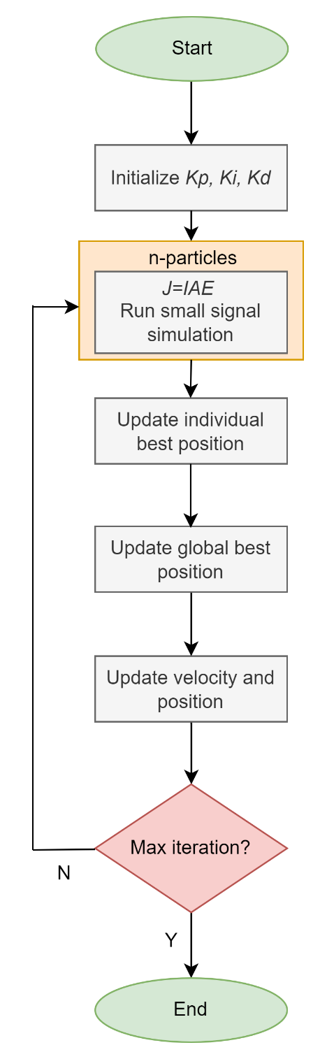
Figure 4. Flowchart of PSO tuning PID
- RESULT AND DISCUSSION
To evaluate the performance of the proposed PID-PSO, two tests were conducted: a speed variation test and a load variation test. The system was designed with a 2% tolerance band for speed control. Performance was assessed using three key metrics: settling time, overshoot/undershoot (OS/US), and the IAE, which quantifies the accumulated tracking error throughout the simulation. Table 3 presents the manually tuned and PSO-optimized PID parameters used in the simulations.
Table 3. PID parameters
Parameters | Manual | PSO |

| 5 | 10 |

| 10 | 9.66 |

| 0 | 0 |
- Speed Variation Test
The motor was subjected to three step changes in speed: 50 rpm, 100 rpm, and 80 rpm. The corresponding simulation results for speed, torque, and IAE are shown in Figure 5. In Figure 5(a), both controllers successfully track the speed reference. Visually, PID-PSO shows a faster rise and smaller overshoot. However, quantitative analysis reveals that conventional PID achieves faster settling times for most steps when using a 2% tolerance criterion. This discrepancy arises because the PID response crosses the steady-state band earlier, even though it appears slower in the plot, highlighting the importance of defining performance metrics precisely. The torque responses in Figure 5(b) are similar between both methods, though PID-PSO produces sharper peaks during speed changes. The IAE comparison in Figure 5(c) shows that PID-PSO achieves a significantly lower cumulative error over the entire simulation. Quantitative performance data are summarized in Table 4. PID-PSO achieves a 37.79% reduction in cumulative IAE (from 52.26 to 34.08) compared to PID. Additionally, PID-PSO consistently reduces overshoot and undershoot, improving steady-state performance.
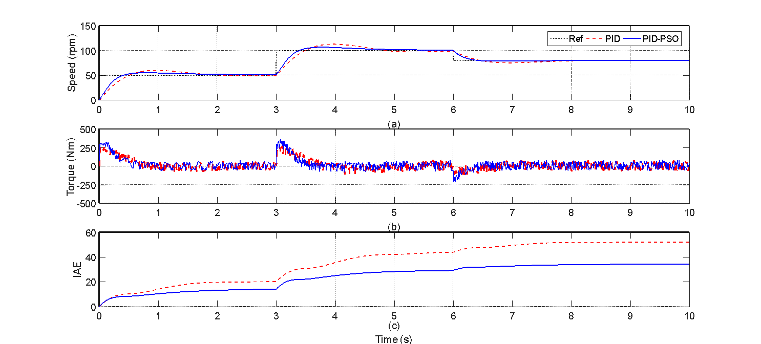
Figure 5. Speed variation test results
Table 4. Results of speed variations
Control method | Settling time (s) | OS/ US (%) | IAE |
Set-point-1: 50rpm |
PID | 1.98 | 20.64 |
|
PID-PSO | 2.29 | 9.40 |
|
Set-point-2: 100rpm |
PID | 1.75 | 13.32 |
|
PID-PSO | 1.83 | 6.28 |
|
Set-point-3: 80rpm |
PID | 1.66 | -5.53 | 52.26 |
PID-PSO | 1.11 | -2.29 | 34.08 |
- Load Variation Test
This test evaluated controller robustness under varying mechanical load conditions at a constant speed set-point of 100 rpm. The system was subjected to an increase and subsequent decrease in load. Figure 6(a) shows that PID-PSO produces lower overshoot and undershoot during load disturbances compared to PID. Torque responses in Figure 6(b) are similar for both controllers. As shown in Figure 6(c), PID-PSO again outperforms PID in terms of IAE, indicating better overall tracking performance. Table 5 summarizes the performance metrics. While the PID controller maintains a faster settling time (2.23 s vs. 2.93 s), PID-PSO achieves a 14.76% reduction in total IAE and significantly lower overshoot/undershoot during load transients.
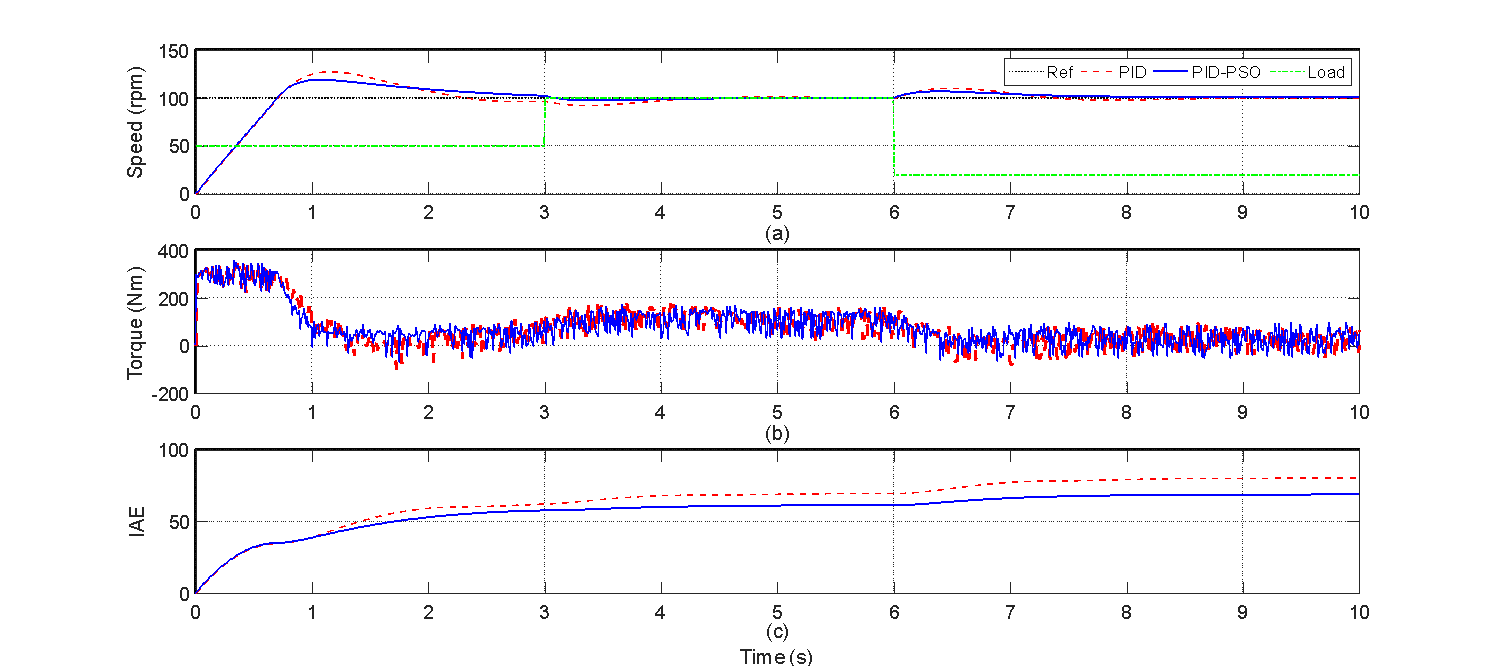
Figure 6. Load variation test results
Table 5. Results of load variations
Control method | Settling time (s) | OS/ US (%) | IAE |
Set-point-1: 100rpm |
PID | 2.23 | 27.51 |
|
PID-PSO | 2.93 | 18.53 |
|
Increase load |
PID |
| 7.58 |
|
PID-PSO |
| 3.13 |
|
Decrease load |
PID |
| 10.33 | 80.51 |
PID-PSO |
| 6.40 | 68.63 |
The main findings confirm that the PID-PSO controller significantly reduces IAE and overshoot/undershoot across both test scenarios, although it introduces a modest increase in settling time compared to conventional PID. This trade-off between speed of response and accuracy is typical when optimizing a single objective (IAE), as done in this study. The limitation of this study is the optimization focused solely on IAE, overlooking other industrially relevant objectives such as robustness to parameter variation (e.g., rotor resistance changes) and actuator constraints (e.g., saturation). Despite these limitations, the study demonstrates the potential of PSO to improve control accuracy, especially in scenarios where overshoot and error accumulation are critical. Future work should consider multi-objective optimization and validate against more complex or real-time models.
- CONCLUSIONS
This study presented the design and simulation of an induction motor speed control system using a PID controller optimized by PSO (PID-PSO). A black-box modeling approach was employed to derive a reduced-order state-space model for PID tuning. The PSO algorithm was applied with the IAE as the objective function to enhance control accuracy. The controller's performance was evaluated through speed and load variation tests. While the manually tuned PID controller achieved faster settling times, the PID-PSO method significantly outperformed it in terms of overshoot, undershoot, and overall control accuracy. Specifically, PID-PSO reduced the IAE by 37.79% during speed variation and by 14.76% during load variation compared to manual PID tuning. These improvements indicate enhanced stability and tracking performance, which are critical for precise motor control. However, the modeling approach simplifies the nonlinear dynamics of the induction motor, which may limit real-world applicability. Future work should consider high-fidelity modeling and experimental validation to address this limitation. Moreover, integrating multi-objective optimization could further enhance the controller's ability to balance trade-offs between performance metrics such as settling time and transient behavior.
DECLARATION
Author Contribution
All authors contributed equally to the main contributor to this paper. All authors read and approved the final paper.
Funding
This research was funded by HGR-Penelitian UNS No. 371/UN27.22/PT.01.03/2025.
Conflicts of Interest
The authors declare no conflict of interest.
REFERENCES
- L. Gumilar, I. Ridzki, A. Muazib, A. I. Syah, and M. Z. Falah, “Dynamic Voltage Restorer for Mitigation of Voltage Sags Due to 3 Phase Motor Starts Based on Artificial Neural Networks,” J. Ilm. Tek. Elektro Komput. and Inform., vol. 9, no. 1, pp. 200–211, 2023, https://doi.org/10.26555/jiteki.v9i1.25897.
- M. E. Sulistyo, D. D. Susilo, M. Nizam, and U. Ubaidillah, "A Literature Review: Bearing Fault in BLDC Motor Based on Vibration and Thermal Signals," J. Electr., Electron., Inf., Commun. Technol., vol. 7, no. 1, pp. 10–15, 2025, https://doi.org/10.20961/jeeict.7.1.100165.
- A. R. Al Tahtawi, S. Yahya, P. Elbizzar, and S. M. Ilman, "Speed Control of 3 Phase 1.5 kW Induction Motor using VSD LS SV015IG5A-2 with Proportional Integral Anti-Windup Method," J. Fuzzy Syst. Control, vol. 2, no. 3, pp. 140–146, 2024, https://doi.org/10.59247/jfsc.v2i3.242.
- H. Maghfiroh, A. J. Titus, A. Sujono, F. Adriyanto, and J. S. Saputro, “Induction Motor Torque Measurement using Prony Brake,” Int. J. Robot. Control Syst., vol. 2, no. 3, pp. 594–605, 2022, https://doi.org/10.31763/ijrcs.v2i3.782.
- H. Maghfiroh, I. Iftadi, and A. Sujono, “Speed Control of Induction Motor using LQG,” Journal of Robotics and Control (JRC), vol. 2, no. 6, pp. 565-570, 2021, https://doi.org/10.18196/26138.
- M. Swargiary, J. Dey, and T. K. Saha, “Optimal Speed Control of Induction Motor Based on Linear Quadratic Regulator Theory,” Annual IEEE India Conference (INDICON), 2015, https://doi.org/10.1109/INDICON.2015.7443806.
- M. Magzoub, N. Saad, R. Ibrahim, and M. Irfan, “An experimental demonstration of hybrid fuzzy-fuzzy space- vector control on AC variable speed drives,” Neural Computing and Applications, pp. 1-16, 2017, https://doi.org/10.1007/s00521-017-3008-6.
- B. R. Ke, H. Maghfiroh, K. L. Lian, N. Chen, and D. F. Teshome, “Model of traction system and speed control for single train of Taipei mass rapid transit system,” IEEE International Conference on Advanced Intelligent Mechatronics (AIM), pp. 781-787, 2016, https://doi.org/10.1109/AIM.2016.7576863.
- M. M. Islam, S. A. Siffat, I. Ahmad, and M. Liaquat, “Adaptive Nonlinear Control of Unified Model of Fuel Cell, Battery, Ultracapacitor and Induction Motor Based Hybrid Electric Vehicles,” IEEE Access, vol. 9, pp. 57486-57509, 2021, https://doi.org/10.1109/ACCESS.2021.3072478.
- H. Maghfiroh, M. R. Subeno, M. R. Darmawan, and R. Prihananto, “A survey on traction motor and its prototyping method for electric vehicle application,” J. Electr. Electron. Inf. Commun. Technol., vol. 5, no. 1, pp. 21–26, 2023, https://doi.org/10.20961/jeeict.5.1.71317.
- M. Y. A. Khan, “Enhancing electric vehicle performance: A case study on advanced motor drive systems, integration, efficiency, and thermal management,” Control Syst. Optim. Lett., vol. 3, no. 1, pp. 20–27, 2025, https://doi.org/10.59247/csol.v3i1.152.
- H. Maghfiroh and C. Hermanu, “Optimal energy control of railway traction motor: Comparative study,” in AIP Conf. Proc., vol. 2097, no. 1, 2019, https://doi.org/10.1063/1.5098195.
- L. Guangqiang, H. Fei, L. Qiang and J. Yanchao, "Torque close-loop control of a novel soft starter of induction motor," 2013 IEEE International Symposium on Industrial Electronics, pp. 1-6, 2013, https://doi.org/10.1109/ISIE.2013.6563613.
- U. Sengamalai, G. Anbazhagan, T. M. Thamizh Thentral, P. Vishnuram, T. Khurshaid, and S. Kamel, “Three phase induction motor drive: A systematic review on dynamic modeling, parameter estimation, and control schemes,” Energies, vol. 15, no. 21, p. 8260, 2022, https://doi.org/10.3390/en15218260.
- A. Alwadie, “A concise review of control techniques for reliable and efficient control of induction motor,” International Journal of Power Electronics and Drive Systems, vol. 9, no. 3, p. 1124, 2018, http://doi.org/10.11591/ijpeds.v9.i3.pp1124-1139.
- S. Roy and R. Pandey, "Efficiency Optimization of Vector Controlled Induction Motor Drive by Field Orientation Technique," 2023 Third International Conference on Advances in Electrical, Computing, Communication and Sustainable Technologies (ICAECT), pp. 1-5, 2023, https://doi.org/10.1109/ICAECT57570.2023.10118261.
- T. Sutikno, N. R. N. Idris, and A. Jidin, “A review of direct torque control of induction motors for sustainable reliability and energy efficient drives,” Renewable Sustainable Energy Review, vol. 32, pp. 548–58, 2014, https://doi.org/10.1016/j.rser.2014.01.040.
- Y. Zahraoui, M. Akherraz, C. Fahassa, and S. Elbadaoui, “Induction Motor DTC Performance Improvement by Reducing Flux and Torque Ripples in Low Speed,” J. Robot. Control, vol. 3, no. 1, pp. 93–100, 2022, https://doi.org/10.18196/jrc.v3i1.12550.
- V. Shekher, A. Sisodiya, A. K. Sinha, H. Harsh, and N. Soren, "Optimal tuning of PID controller for V/f control of linear induction motor using artificial biological intelligence," Franklin Open, vol. 9, p. 100183, 2024, https://doi.org/10.1016/j.fraope.2024.100183.
- H. Maghfiroh, A. Ma’arif, F. Adriyanto, I. Suwarno, and W. Caesarendra, “Adaptive Linear Quadratic Gaussian Speed Control of Induction Motor Using Fuzzy Logic,” J. Eur. des Systèmes Autom., vol. 56, no. 4, pp. 703–711, 2023, https://doi.org/10.18280/jesa.560420.
- Y. Zahraoui, M. Akherraz, and A. Ma’arif, “A Comparative Study of Nonlinear Control Schemes for Induction Motor Operation Improvement,” Int. J. Robot. Control Syst., vol. 2, no. 1, pp. 1–17, 2021, https://doi.org/10.31763/ijrcs.v2i1.521.
- M. Zhou, S. Cheng, Y. Feng, W. Xu, L. Wang, and W. Cai, “Full-order terminal sliding-mode-based sensorless control of induction motor with gain adaptation,” IEEE Journal of Emerging and Selected Topics in Power Electronics, vol. 10, no. 2, pp. 1978–1991, 2021, https://doi.org/10.1109/JESTPE.2021.3081863.
- C-K. Lin, “Radial basis function neural network-based adaptive critic control of induction motors,” Appl. Soft Computing, vol. 11, no. 3, 3066–3074, 2011, https://doi.org/10.1016/j.asoc.2010.12.007.
- S. Mahfoud, A. Derouich, N. El Ouanjli, and M. El Mahfoud, "Enhancement of the direct torque control by using artificial neuron network for a doubly fed induction motor," Intelligent Systems with Applications, vol. 13, p. 200060, 2022, https://doi.org/10.1016/j.iswa.2022.200060.
- M. Meriem, G. Ahmed and M. Youness, "Speed Control of Induction Motor using Fuzzy Logic Controller and DTC Strategy," 2024 4th International Conference on Innovative Research in Applied Science, Engineering and Technology (IRASET), FEZ, pp. 1-5, 2024, https://doi.org/10.1109/IRASET60544.2024.10548936.
- H. Maghfiroh, J. Slamet Saputro, F. Fahmizal, and M. Ahmad Baballe, “Adaptive Fuzzy-PI for Induction Motor Speed Control,” J. Fuzzy Syst. Control, vol. 1, no. 1, pp. 1–5, 2023, https://doi.org/10.59247/jfsc.v1i1.24.
- E. S. Ghith and F. A. A. Tolba, “Design and Optimization of PID Controller using Various Algorithms for Micro-Robotics System,” J. Robot. Control, vol. 3, no. 3, pp. 244–256, 2022, https://doi.org/10.18196/jrc.v3i3.14827.
- H. Maghfiroh, O. Wahyunggoro, A. I. Cahyadi, and S. Praptodiyono, “PID-hybrid tuning to improve control performance in speed control of DC Motor based on PLC,” 3rd Int. Conf. on Instrumentation Control and Automation (ICA), 2013, pp. 233-238, https://doi.org/10.1109/ICA.2013.6734078.
- W. Findiastuti, A. Dafid, and R. Annisa, “Design of a Device for Utilizing Hazardous and Toxic Waste as Fuel For a Stove (Burner) with a PID Control System,” J. Ilm. Tek. Elektro Komput. dan Inform., vol. 9, no. 2, pp. 319–332, 2023, https://doi.org/10.26555/jiteki.v9i2.26179.
- R. Rikwan and A. Ma’arif, “DC Motor Rotary Speed Control with Arduino UNO Based PID Control,” Control Syst. Optim. Lett., vol. 1, no. 1, pp. 17–31, 2023, https://doi.org/10.59247/csol.v1i1.6.
- M. Zadehbagheri, A. Ma’arif, R. Ildarabadi, M. Ansarifard, and I. Suwarno, “Design of Multivariate PID Controller for Power Networks Using GEA and PSO,” J. Robot. Control, vol. 4, no. 1, pp. 108–117, 2023, https://doi.org/10.18196/jrc.v4i1.15682.
- E. S. Ghith and F. A. A. Tolba, “Design and Optimization of PID Controller using Various Algorithms for Micro-Robotics System,” J. Robot. Control, vol. 3, no. 3, pp. 244–256, 2022, https://doi.org/10.18196/jrc.v3i3.14827.
- M. A. Abdelghany, A. O. Elnady, and S. O. Ibrahim, “Optimum PID Controller with Fuzzy Self-Tuning for DC Servo Motor,” J. Robot. Control, vol. 4, no. 4, 2023, https://doi.org/10.18196/jrc.v4i4.18676.
- E. W. Suseno and A. Ma’Arif, “Tuning of PID Controller Parameters with Genetic Algorithm Method on DC Motor,” Int. J. Robot. Control Syst., vol. 1, no. 1, pp. 41–53, 2021, https://doi.org/10.31763/ijrcs.v1i1.249.
- E. S. Rahayu, A. Ma’arif, and A. Cakan, “Particle Swarm Optimization (PSO) Tuning of PID Control on DC Motor,” Int. J. Robot. Control Syst., vol. 2, no. 2, pp. 435–447, 2022, https://doi.org/10.31763/ijrcs.v2i2.476.
- P. L. Nguyen, D. Q. Le, Q. B. Lam, A. T. Tran, T. T. Nguyen, D. L. Pham, and B. H. Nguyen, "Adaptive Evaluation of LQR Control using Particle Swarm Optimization for Pendubot," Journal of Fuzzy Systems and Control, vol. 2, no. 2, pp. 58–66, 2024, https://doi.org/10.59247/jfsc.v2i2.203.
- E. S. Rahayu, A. Ma'arif, and A. Cakan, "Particle swarm optimization (PSO) tuning of PID control on DC motor," International Journal of Robotics and Control Systems, vol. 2, no. 2, pp. 435–447, 2022, https://doi.org/10.31763/ijrcs.v2i2.476.
- Z. Qu, W. Younis, X. Liu, A. K. Junejo, S. Z. Almutairi, and P. Wang, “Optimized PID controller for load frequency control in multi-source and dual-area power systems using PSO and GA algorithms,” IEEE Access, 2024, https://doi.org/10.1109/ACCESS.2024.3445165.
- O. S. Ebrahim, M. F. Salem, P. K. Jain, and M. A. Badr, “Application of linear quadratic regulator theory to the stator field-oriented control of induction motors,” IET Electr. Power Appl., vol. 4, no. 8, pp. 637–646, 2010, https://doi.org/10.1049/iet-epa.2009.0164.
- T. Abut, “Modeling and Optimal Control of a DC Motor,” Int. J. Eng. Trends Technol., vol. 32, no. 3, pp. 146–150, 2016, https://doi.org/10.14445/22315381/IJETT-V32P227.
- H. Maghfiroh, M. Nizam, M. Anwar, and A. Ma’Arif, “Improved LQR Control Using PSO Optimization and Kalman Filter Estimator,” IEEE Access, vol. 10, pp. 18330–18337, 2022, https://doi.org/10.1109/ACCESS.2022.3149951.
- N. Thongpance, P. Chotikunnan, A. Wongkamhang, R. Chotikunnan, P. Imura, W. Khotakham, A. Nirapai, and K. Roongprasert, "Comparative analysis of PID tuning methods for speed control in Mecanum-wheel electric wheelchairs," Buletin Ilmiah Sarjana Teknik Elektro, vol. 7, no. 2, pp. 95–110, 2025, https://doi.org/10.59247/csol.v2i3.161.
Induction Motor Speed Control Using PID Tuned by Particle Swarm Optimization Under Vector Control (Hari Maghfiroh)