Buletin Ilmiah Sarjana Teknik Elektro ISSN: 2685-9572
Dielectric Characterization of Breast Cancer Cells using Split-Rectangular Ring Resonator Sensor
Adamu Halilu Jabire 1, Sani Saminu 2, Mohammed Jajere Adamu 3, Abubakar Saddiq Mohammed 4, Sha’awanatu Aminu 5, Abubakar Muhammad Sadiq 5
1 Department of Electrical and Electronics Engineering, Taraba State University, Jalingo, Nigeria
2 Department of Biomedical Engineering, University of Ilorin, Ilorin, Nigeria
3 Department of Electronic Science and Technology, School of Microelectronics, Tianjin University, China
4 Department of Telecommunication Engineering, Federal University of Technology Minna, Nigeria
5 Tianjin Key Laboratory of Imaging and Sensing Microelectronic Technology, School of Microelectronics, Tianjin University, Tianjin, China
ARTICLE INFORMATION |
| ABSTRACT |
Article History: Received 26 December 2024 Revised 24 February 2025 Accepted 02 March 2025 |
| 
Exploring a universal method to enhance the performance of metamaterials by quantifying the impact of gap capacitance is an intriguing topic for many researchers. However, achieving this through conventional methods is extremely challenging. In this paper, we present a microwave sensor designed to characterize cancerous cells based on their electrical properties. The proposed design features a split rectangular ring resonator placed on a flame-retardant four (FR-4) substrate. The sensor aims to achieve high sensitivity and quality factors through the unique characteristics of the metamaterial structure in the GHz frequency range. Through simulations and experimental measurements, we demonstrate the sensor's effective capabilities in detecting cancer. The high sensitivity for both simulation and measurement, is estimated at 10 %. The simulations and validation confirm that this biosensor exhibits significant frequency shifts and high sensitivity. Our proposed configurations highlight the microwave sensor's potential for detecting six different breast cancer cell types: HSS-2, HS578-T_nm, MCF-2, MCF-10A_nm, T-47D, and T-47D_nm. Based on the existing literatures, the sensitivity of the proposed sensor is determined to be greater. |
Keywords: Split Rectangular-ring Resonator; Metamaterial; Microwave Sensor; Sensitivity |
Corresponding Author: Adamu Halilu Jabire, Department of Electrical and Electronics Engineering, Taraba State University, Jalingo, Nigeria. Email: adamu.jabire@tsuniversity.edu.ng |
This work is licensed under a Creative Commons Attribution-Share Alike 4.0 
|
Document Citation: A. H. Jabire, S. Saminu, M. J. Adamu, A. S. Mohammed, S. Aminu, and A. M. Sadiq, “Dielectric Characterization of Breast Cancer Cells using Split-Rectangular Ring Resonator Sensor,” Buletin Ilmiah Sarjana Teknik Elektro, vol. 7, no. 1, pp. 42-55, 2025, DOI: 10.12928/biste.v7i1.12680. |
- INTRODUCTION
Sensors are devices that can measure the physical inputs of the surrounding environment and convert them into data that can be measured/read by humans or machines. The five basic sensory systems in the human body are the visual system, auditory system, olfactory (smell) system, gustatory (taste) system, and tactile system [1]. Nowadays, the incredible progress in material science, micromachining and thin-film technologies, and printing capabilities have brought about a broad range of possibilities for the development of sensors in various applications. In addition, with the overwhelming advancement in mobile apps, sensors have become an integral part of the IoT network, providing individuals with real-time monitoring capabilities in the healthcare sector, security, and even the gaming industry [2][3]. Microwave sensors are widely used across industrial, biological, and electronic sectors due to their numerous advantages. These benefits include high sensitivity, versatility, low fabrication costs, and straightforward measurement procedures. The sensing principle of microwaves is based on band-pass filter technology. Resonator-based sensors function by detecting changes in the resonant frequency of a resonator element when the material under test (MUT) is placed on its surface. The magnitude and resonant frequency of the frequency response shift from the original resonance frequency of the structure, depending on the permittivity and thickness of the MUT. Planar resonator-based structures operating over a wide frequency range from microwave to terahertz (THz) show significant promise for various sensing applications.
In recent years, metamaterials (MTM) have become increasingly significant in sensing technology. Metamaterials are engineered materials composed of various structures that exhibit unique properties. The properties of these structures depend on their orientation, dimensions, shape, and the material used for the base. The increasing interest in metamaterials stems from their size relative to the electromagnetic waves they interact with, as the target wavelength is larger than the dimensions of the structural elements [4][5]. Various applications of metamaterials include biosensors [6], antennas [7], energy harvesting [8], microwave sensors [9], synthetic aperture radar (SAR) reduction [10, and microwave lenses [11]. Split-ring resonator (SRR) based metamaterials are particularly valued for their adaptability and the practical shape of their resonators. The SRR is the most frequently used structure among metamaterials. Depending on the geometry, it works as an LC resonant circuit resonating at a certain frequency. Another factor that affects resonant frequency is the dielectric material in the gap [12]-[14]. SRR structure varies from centimeters to nanometers. For microwave band applications, structures in centimeters to millimeters are used. Micrometer structures are used for THz frequency applications, and nanometer structures are implemented in the infrared and visible light spectrum [15][16]. The shift in resonance frequency can effectively differentiate the tested materials [17]. The success of this technique relies on variations in resonance frequency caused by differences in the cellular properties of the materials. It provides precise control over the frequency range used for differentiation. According to Kerouedan et al. [18], the resonance frequency technique generally exhibits higher accuracy than the reflection coefficient-based technique. It has emerged as an interesting sensing technology that exhibits unique properties tailored by the structure and composition of the tested material. Sensors that use metamaterials detect changes in the electromagnetic field when interacting with the material being tested. These changes in the field lead to shifts in resonance frequency and variations in the response signal amplitude [19]. This technique has been used to develop a sensor for various detection applications in different areas ranging from electronics, biological, and material science applications [20]-[28].
A microwave sensor has been developed for the dielectric characterization of biological samples [29]. This resonant configuration features two capacitively coupled printed Split Ring Resonators (SRRs) created using inkjet printing technology. Additionally, a contactless microwave sensor based on Complementary Split Ring Resonators (CSRRs) has been introduced for the dielectric characterization of liquids. This design employs multiple CSRRs, with a glass capillary tube inserted into the electric field region of the CSRRs, which acts as a container for the tested liquid [30]. A dual scale planar sensor for dielectric characterization of solid material was presented in [31]; although it has a good sensitivity, the design is complex. [32] reported a temperature-compensated differential microstrip sensor for microfluidic application. The sensor has a splitter section with two symmetrical complementary split ring resonators. The major disadvantage is that a high cost substrate was used as an aligned slot to the CSRR. A solid material permittivity characterization was reported in [33]; the sensitivity is low compared to the one presented in this work. As detailed in [34], a high-sensitivity microfluidic sensor based on CSRR with an interdigital structure is presented. The microwave sensor exhibits a single frequency band with a low sensitivity. Similar research has been reported in [35], with a lower sensitivity of 4.915% and a high-cost substrate
This research aims to categorize and distinguish different types of breast cancer cells according to their electrical properties. This investigation will focus on six specific cancer cell lines: HSS-2, HS578-T_nm, MCF-2, MCF-10A_nm, T-47D, and T-47D_nm. The electrical properties of these cancerous cells were obtained from prior studies conducted by researchers in the field [36]. The letter consists of four sections. Section 2 offers a microwave sensor design process, theoretical analysis, the proposed sensor configuration, and the Floquet model. Section 3 describes the simulation results. In section 4, the measured outcomes and the hardware prototype are examined. Section 5 provides the concluding remarks.
- METHODS
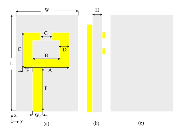
The proposed microwave sensor consists of a sensing patch arrangement that is activated by a single-port microstrip, as shown in Figure 1. The conductive ring carries current when a magnetic field interacts with the SRR, which is a rectangular metallic loop featuring a narrow gap between each ring. Due to the gap that prevents current flow, the LC circuit becomes more resonant. The inductive and capacitive reactances must be of equal amplitude for resonance to occur [37]. Sensors can be made with SRR because the space acts as a capacitor. As shown in Figure 1, W1 is used to excite the sensor, which produces a single-band responses of 6.7 GHz. In this sensor, the top layer of the substrate is carved from an FR4 material that measures 1.6 mm in thickness, possesses a relative permittivity of 4.3, and has a loss tangent of 0.025. As part of the optimization and validation of the sensor performance, computer simulation technology suite (CST) was used. According to Table 1, The proposed sensor has the following optimal parameters.
Figure 1. Microwave sensor structure (a) Upper layer (b) Side view (c) Bottom layer
Table 1. Optimized sensor geometry
Parameter | Size (mm) | Parameter | Size (mm) |
A | 14 | F | 19.7 |
B | 9.36 | G | 2 |
C | 10 | L | 40 |
D | 2.32 | W | 20 |
E | 3 | Wf | 3.1 |
- Theoretical analysis
A dielectric resonator's resonant frequency shifts to a lower value when a material under test (MUT) is present, to put it another way. The MUT's complex permittivity directly affects how much of a shift this is. The resonance frequency shift increases with the permittivity value. The following formula explains this frequency shift [38]-[43].
| 
| (1) |
In this context,  denotes the frequency of resonance, where ε represents the permittivity and μ signifies the permeability. The variables
  and
and  correspond to the electric and magnetic fields in a discharged state, respectively, while
  and
and  indicate the fields observed in the presence of the material under test (MUT). The proposed sensor design also, capitalizes on the SRR capacitive and inductive resonance properties. According to equation (2) [44][45].
| 
| (2) |
The terms  and
and  denote the effective inductance and capacitance associated with the resonator [38]. The basic formula for capacitance (
 ) is given by
| 
| (3) |
The relative permittivity of vacuum is denoted as  , while
  represents the relative permittivity of the dielectric material. The parameters A and d refer to the area of the gap and the distance of the gap, respectively. Given that , A, and d remain constant for a specific sample, the capacitance is influenced by the value of . This value is contingent upon the unique associated with each cancer cell, which ultimately results in alterations to the frequency of resonance of the split-ring resonator (SRR).
- RESULT AND DISCUSSION
- Evolution Steps
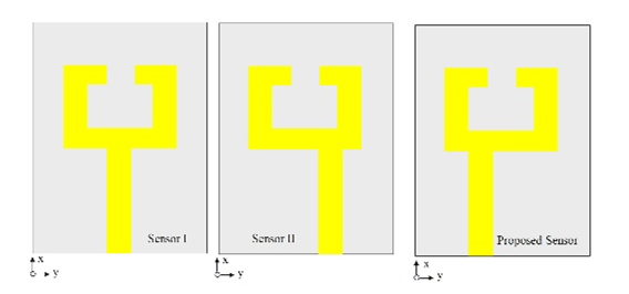
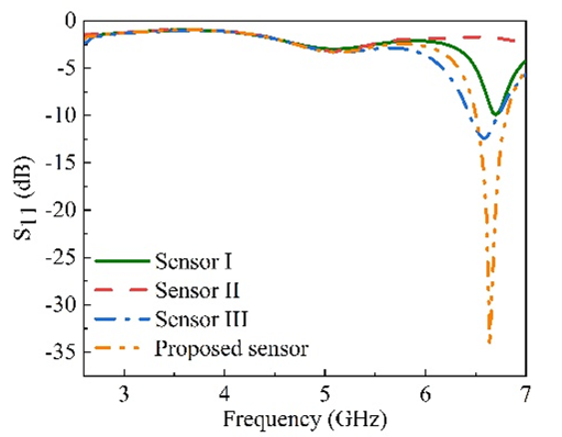
As shown in Figure 2(a), there are several procedures that should be followed in order to complete the development of a microwave sensor. In terms of frequency range, the MTM MIMO antenna can operate anywhere from 3 to 7 GHz. According to Figure 2(b), sensor I's  response does not meet expectations due to the port's position. Shifting the feedline sideways in a right direction, further enhances the single band characteristics of the response. The third phase of the proposed sensor involved shifting the feeding port position to a left direction. This revised configuration improves the sensors performance regarding impedance matching.
The variation in design parameters, such as resonator width ( ), gap capacitance (
 ), and the substrate's permittivity value, leads to changes in the transmission coefficient () and resonance frequency (). The width of the sensor resonator has a significant impact on the total inductance, which in turn affects the resonance frequency. Adjusting the width of the resonator is essential for modifying the inductance value, directly influencing the resonance frequency of the metamaterial. The primary purpose of incorporating a split gap in the metamaterial resonator is to alter the sensor's resonance frequency. This split gap introduces capacitance, which directly affects the resonance frequency. Therefore, the capacitance resulting from the gap is crucial for changing the capacitance value, which has a direct effect on the resonant frequency (). Additionally, the permittivity () of the substrate material influences the resonant frequency since it is associated with capacitance. Therefore, the design parameters were evaluated to enhance the proposed sensor.
| 
|
(a) | (b) |
Figure 2. Evolution stages of the suggested sensor (a), S11 response of the various stages (b)
Figure 3 demonstrates the influence of resonator width on both the resonance frequency () and the return loss (). The analysis is conducted for resonator widths of 5.24, 5.28, 5.36, 5.4, and 6mm. The main impact of introducing a resonator into a metamaterial resonator patch is the alteration of the sensor's resonance frequency. This is one of the significant effects observed. Table 2 presents the changes in and associated with the different resonator widths. According to Table 2, the 5.36mm resonator width demonstrates superior performance compared to the others, leading to the selection of 5.36mm as the resonator width.
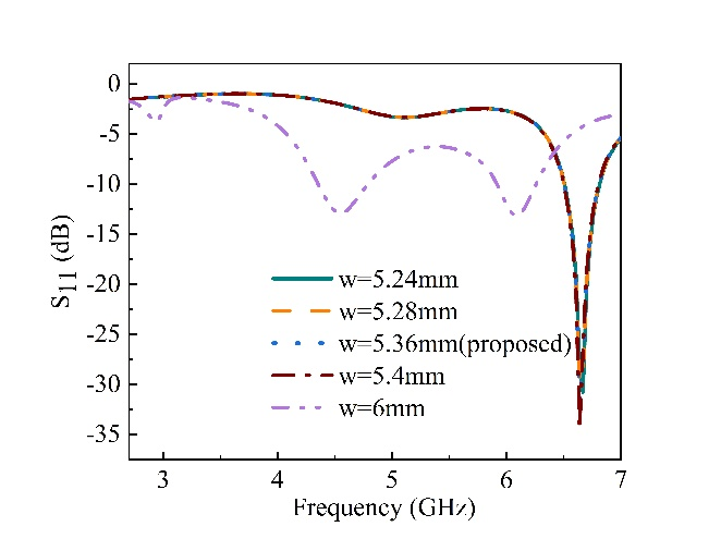
Figure 3. Variation of frequency and magnitude for resonator width ()
Table 2. The effect of the resonator width () on the frequency () and amplitude
Width (mm) | Freq range (GHz) | (GHz) | (dB) |
5.24 | 3 - 7 | 6.76 | -32 |
5.28 |
| 6.6 | -30 |
5.36 (proposed) |
| 6.7 | -34 |
5.4 |
| 6.78 | -34 |
6 |
| 6 | -12 |
Figure 4 shows how the gap capacitance () influences the resonant frequency () and return loss (). The results were calculated for split gaps of 1mm, 2mm, 2.4mm, 2.8mm, and 3.2mm, corresponding to five different resonator configurations. Table 3 illustrates the variations in and with the various gap capacitance. According to Table 3, the 2mm split gap shows the best performance compared to the other options, making it the preferred choice. Figure 5 illustrates how substrate permittivity () affects the resonant frequency () and the reflection coefficient (), with a proposed value of 4.3. The results were assessed for permittivity values of 3.26, 3.46, 3.66, 3.77, and 4.3. Table 4 presents the variations of and based on these different permittivity values. From Table 4, it is evident that a permittivity value of 4.3 outperforms the others, making it the preferred choice for substrate permittivity.
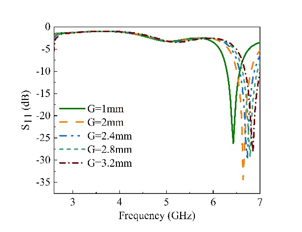
Figure 4. Variation of frequency and magnitude for gap capacitance ( )
)
Table 3. The impact of gap capacitance on the resonance frequency () and amplitude
Gap capacitance (mm) | Freq range (GHz) |  (GHz) (GHz)
| (dB) |
1 | 3 - 7 | 6.4 | -26 |
2 (proposed) |
| 6.5 | -35 |
2.4 |
| 6.75 | -30 |
2.8 |
| 6.8 | -29 |
3.2 |
| 6.85 | -27 |
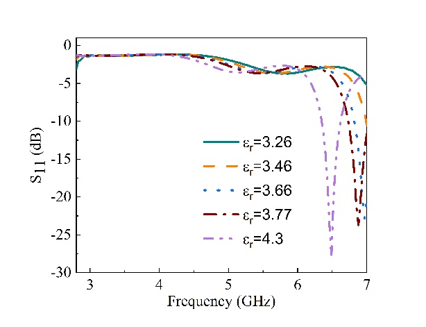
Figure 5. Change in frequency and magnitude due to the alteration of substrate
permittivity ()
Table 4. Effect of substrate permittivity () on the resonance frequency and in dB.
Substrate permittivity () | Freq range (GHz) | (GHz) | (dB) |
3.26 | 3 - 7 | 6.9 | -22 |
3.46 |
| 2.6 | -18 |
3.66 |
| 7 | -23 |
3.77 |
| 6.85 | -23 |
4.3(proposed) |
| 6.5 | -28 |
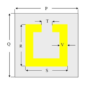
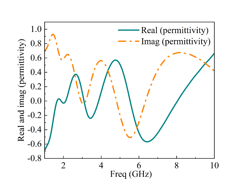
- Floquet Model
The floquet model presented in Figure 6(a) is composed of a simple two dimensional rectangular loop with a gap capacitance in between the resonator. The unit cell has three coordinates that is, xyz. The z-axis will be our negative permeability for the boundary condition while the x-axis is a two opening where the port will be inserted which propagate waves, finally y-axis will be perfectly electric. The electric or magnetic permittivity retrieval is set using S-parameter retrieval techniques. The unit cell metamaterial permeability real and imaginary part is pictured in Figure 6(b) while Figure 7 is the MTM and  . The dimensions are presented in Table 6.
| 
|
(a) | (b) |
Figure 6. Floquet model geometry (a) Permeability real and imaginary part (b)
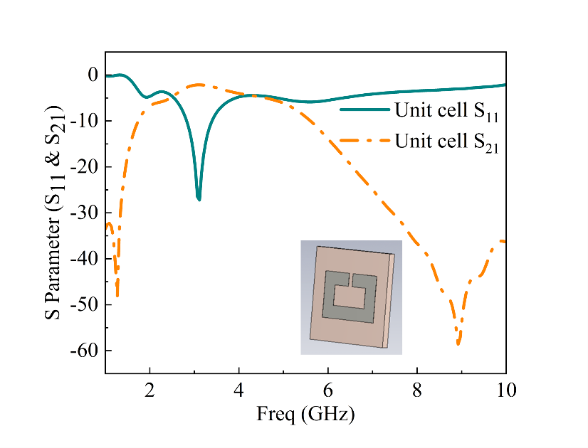
Figure 7. The floquet unit cell and
Table 6. Optimized unit cell dimensions
Parameter | Size (mm) | Parameter | Size (mm) |
P | 20 | S | 14 |
Q | 30 | T | 2 |
R | 10 | V | 2.32 |
- Simulation Results
The microwave sensor model depicted in Figure 8 simulates the sensor's response by integrating different cell types within the sensor gap. This was accomplished by populating the resonator's gap with representations of breast cancer cells, modeled as hemispherical entities with a diameter of 2mm. The electrical properties of these malignant breast cells were derived from the research conducted by [46]. Figure 8 shows how the resonance characteristics of vacuum differ from those of the Five cells (HSS-2, HS578-T_nm, MCF-2, MCF-10A_nm, T-47D, and T-47S_nm). For every cell used, the electrical conductivity and dielectric constant are shown in Table 7. One standard is the vacuum resonance characteristics. Maximum transmission shift occurs at resonance frequencies of 5.5GHz. The difference in resonance frequency between two adjacent cell types is as small as 1.2 GHz.
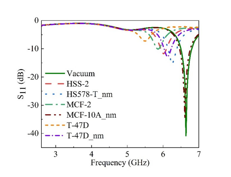
Figure 8. Simulated shift in decibel
Table 7. Dielectric constant and the conductivity of the cell
Cancer cell | HSS-2 | HS578-T_nm | MCF-2 | MCF-10A_nm | T-47D | T-47D_nm |
| 43.8 | 19.8 | 42.2 | 2.83 | 71.9 | 26.6 |

| 1.7081 | 0.8123 | 1.5726 | 0.0759 | 2.5622 | 1.1084 |
The shift in resonance frequency of cancerous cell compared to air's resonance frequency is shown in Table 8
Table 8. Shift in frequency in respect to vacuum resonance
Cancer cell | HSS-2 | HS578-T_nm | MCF-2 | MCF-10A_nm | T-47D | T-47D_nm |
Freq shift | 0.62GHz | 0.38GHz | 0.78GHz | 0.03GHz | 1.14GHz | 0.51GHz |
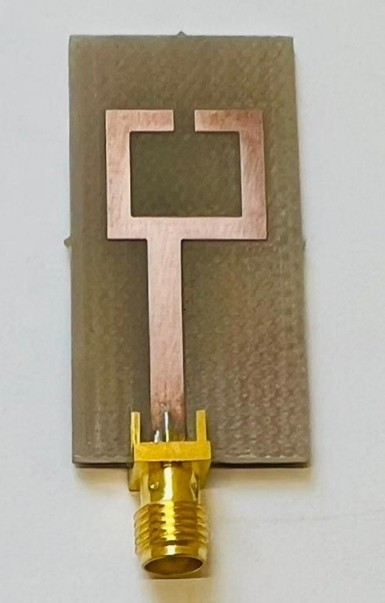
Different kinds of breast cancer cells have been successfully used to test the proposed sensor. An illustration of the measurement setup can be found in Figure 9, with a span of frequency range from 2GHz to 7GHz. A simulation will be conducted to generate and compare different cancer cell responses. FR-4 laminates, which have a thickness of 1.6mm and a dielectric constant of 4.3, were used to build the sensor. Figure 10 shows the printed prototype that has been finished. Air surrounds the sensor because of the way it is positioned. To deposit the cells onto the gap, a micropipette was used. The sensor was exposed to two drops, forming a hemispherical droplet with a 2mm diameter. The sensor was cleaned with ethanol after each sample was measured, and an air pump was used to let it dry. During the measurement, six kinds of cancer cells were examined: HSS-2, HS578-T_nm, MCF-2, MCF-10A_nm, T-47D, and T-47D_nm. The S11 parameters were acquired and recorded in each instance.

Figure 9. Measurement setup
| 
|
(a) | (b) |
Figure 10. Prototype views of the microwave sensor (a) upper plane, (b) lower plane
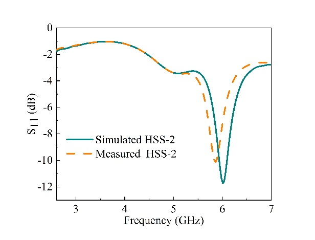
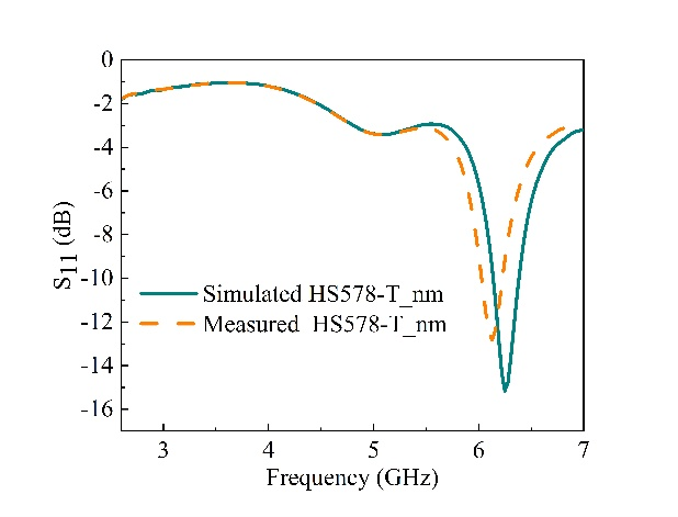
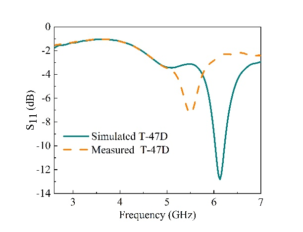
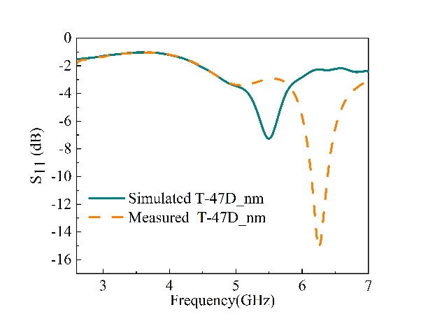
The results of measuring the resonance characteristics of HSS-2, HS578-T_nm, MCF-2, MCF-10A_nm, T-47D, and T-47D_nm, in comparison to the resonance characteristics of a vacuum, are shown in Figure 11. The simulation results are compared with the lab measurements. The vacuum is established as a baseline, and the frequency change for the six distinct cancer cells is determined.
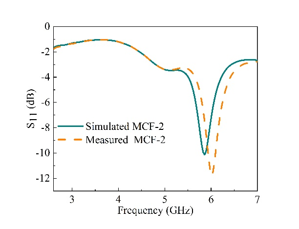
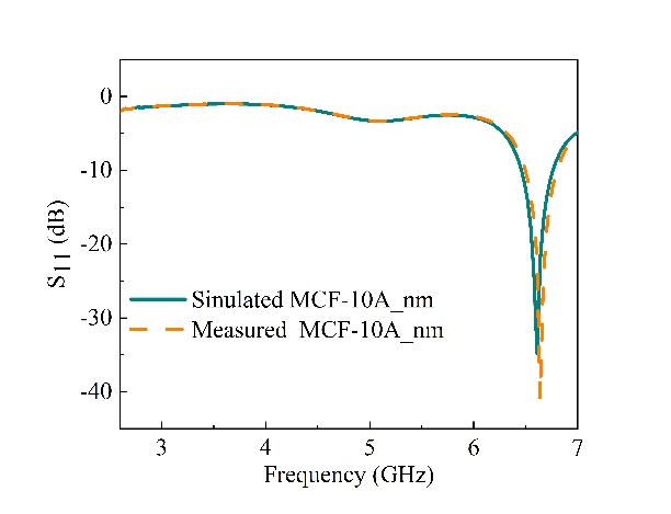
Figure 12, Figure13, and Figure14 show the comparison. The discrepancies noted between the simulated and measured values may result from calibration and manufacturing errors and this can be reduced by taking at least two to three times calibration process. The highest shift achieved between the simulation and the measurement is 0.1GHz. Table 9 presents a summary of the recorded values and the variation in frequency response of the six cells in relation to vacuum resonance frequency.
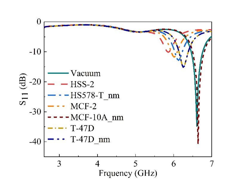
Figure 11. Measured in decibel
| 
|
(a) | (b) |
Figure 12. Simulated and measured (a) HSS-2 (b) HS578-T_nm
| 
|
(c) | (d) |
Figure 13. Simulated and measured (c) MCF-2 (d) MCF-10A_nm
| 
|
(e) | (f) |
Figure 14. Simulated and measured (e) T-47D (f) T-47D_nm
Table 9. Lab measurements
Cancer cell | HSS-2 | HS578-T_nm | MCF-2 | MCF-10A_nm | T-47D | T-47D_nm |
Fr (GHz) | 6 | 6.2 | 5.9 | 6.6 | 5.5 | 6.1 |

| 0.7 | 0.5 | 0.8 | 0.1 | 1.2 | 0.6 |
The microwave sensor attained a peak relative sensitivity of 0.1, with the sensitivity determined through the formula outlined below [47]-[50].
| 
| (4) |
The sensitivity measured for the six cells using vacuum as a reference was 0.02 for HSS-2, 0.03 for HS578-T_nm, 0.02 for MCF-2, 0.1 for MCF-10A_nm, 0.016 for T-47D and 0.023 for T-47D_nm. The discrepancies in the shift was due to different dielectric permittivity value of each breast cancer cell. The performance of the sensor has been evaluated in relation to recent studies published in the literature, as presented in Table 10. Taking into account the sensing range, based on the existing literatures, the sensitivity of the proposed sensor is determined to be greater.
Table 10. Comparison of sensitivity with recent literatures
Reference |  (GHz) (GHz)
| Sensitivity (%) | Substrate used |
[31] | 112 | 9 | Rogers 5880 |
[32] | 2.23 | 0.737 | RT Duroid 4350 |
[33] | 5.11 | 3.27 | RT Duroid 4350 |
[34] | 2.65 | 1.23 | Rogers 4350B |
[35] | 3.364 | 4.915 | Taconic TLY-5 |
This work | 6.7 | 10 | FR-4 |
- CONCLUSIONS
In this research, we developed a microwave sensor that uses metamaterial technology to analyze various types of cancer cells based on their electrical properties. The proposed sensor incorporates a single split ring resonator (SRR) and is designed with a rectangular microstrip-fed grounded planar configuration. We simulated and evaluated the sensor's performance using six different types of cancer cells: HSS-2, HS578-T_nm, MCF-2, MCF-10A_nm, T-47D and T-47D_nm, along with a vacuum serving as a reference. The sensor exhibits strong sensing capabilities for both the simulations and measurements across a frequency range of 3GHz to 7GHz. In the future, this concept may be combined with supplementary elements to develop an autonomous device that enhances both functionality and adaptability to various environments and tasks. By integrating advanced technologies like artificial intelligence, machine learning, and sensor systems, the device can be improve in terms of its sensitivity.
ACKNOWLEDGEMENT
The author will like to acknowledge the Tertiary Education Trust Fund (TETFUND) Taraba State University chapter for their kind support.
REFERENCES
- Z. Mehrjoo, A. Ebrahimi, G. Beziuk, F. Martín and K. Ghorbani, "Microwave Rotation Sensor Based on Reflection Phase in Transmission Lines Terminated With Lumped Resonators," in IEEE Sensors Journal, vol. 23, no. 7, pp. 6571-6580, 2023, https://doi.org/10.1109/JSEN.2023.3236638.
- M. A. H. Ansari, A. K. Jha, Z. Akhter and M. J. Akhtar, “Multiband RF planar sensor using complementary split ring resonator for testing of dielectric materials,” IEEE Sensors Journal, vol. 18, no. 16, pp. 6596–6606, 2018, https://doi.org/10.1109/JSEN.2018.2822877.
- M. Hussein, “Breast cancer cells exhibits specific dielectric signature in vitro using the open-ended coaxial probe technique from 200 MHz to 13.6 GHz,” Scientific reports, vol. 9, no. 1, p. 4681, 2019, https://doi.org/10.1038/s41598-019-41124-1.
- M. I. Hussein, D. Jithin, I. J. Rajmohan, A. Sham, E. E. M. A. Saeed and S. F. AbuQamar, "Microwave Characterization of Hydrophilic and Hydrophobic Plant Pathogenic Fungi Using Open-Ended Coaxial Probe," in IEEE Access, vol. 7, pp. 45841-45849, 2019, https://doi.org/10.1109/ACCESS.2019.2908061.
- P. Quéffélec et al., "Detection of micro-cracks on metal surfaces using near-field microwave dual-behaviour resonators," in New Developments and Applications in Sensing Technology, Berlin, Springer Berlin Heidelberg, pp. 1 – 13, 2011, https://doi.org/10.1007/978-3-642-17943-3_1.
- M. R. Islam et al., "Tri Circle Split Ring Resonator Shaped Metamaterial With Mathematical Modeling for Oil Concentration Sensing," in IEEE Access, vol. 9, pp. 161087-161102, 2021, https://doi.org/10.1109/ACCESS.2021.3131905.
- X. Song, S. Yan and J. Chen, "A Design of Metamaterial Inspired Resonator for Multifrequency Fluidic Sensors," in IEEE Microwave and Wireless Technology Letters, vol. 33, no. 1, pp. 94-97, 2023, https://doi.org/10.1109/LMWC.2022.3204432.
- E. L. Chuma, Y. Iano, G. Fontgalland and L. L. Bravo Roger, "Microwave Sensor for Liquid Dielectric Characterization Based on Metamaterial Complementary Split Ring Resonator," in IEEE Sensors Journal, vol. 18, no. 24, pp. 9978-9983, 15 Dec.15, 2018, https://doi.org/10.1109/JSEN.2018.2872859.
- S. Harnsoongnoen, "Metamaterial-Inspired Microwave Sensor for Detecting the Concentration of Mixed Phosphate and Nitrate in Water," in IEEE Transactions on Instrumentation and Measurement, vol. 70, pp. 1-6, 2021, https://doi.org/10.1109/TIM.2021.3086901.
- M. Wang et al., "Investigation of SAR Reduction Using Flexible Antenna With Metamaterial Structure in Wireless Body Area Network," in IEEE Transactions on Antennas and Propagation, vol. 66, no. 6, pp. 3076-3086, 2018, https://doi.org/10.1109/TAP.2018.2820733.
- S. Mukherjee, Z. Su, L. Udpa, S. Udpa and A. Tamburrino, "Enhancement of Microwave Imaging Using a Metamaterial Lens," in IEEE Sensors Journal, vol. 19, no. 13, pp. 4962-4971, 1 July1, 2019, https://doi.org/10.1109/JSEN.2019.2903454.
- D. Phokaratkul, A. Martucci, U. Waiwijit, T. Maturos, W. Withayachumnankul, A. Tuantranont, W. Wlodarski, K. Jaruwongrungsee and A. Wisitsoraat, "Microfluidic-based Split-Ring-Resonator Sensor for Real-time and Label-free Biosensing," Procedia Engineering, vol. 120, pp. 163-166, 2015, https://doi.org/10.1016/j.proeng.2015.08.595.
- H. Ghafouri-Shiraz and A. Abdelrehim, "High Perform-ance Patch Antenna Using Circular Split Ring Resonators and Thin Wires Employing Electromagnetic Coupling Improvement," Photonics and Nanostructures – Fundame-ntals and Applications, vol. 21, pp. 19-31, 2016, https://doi.org/10.1016/j.photonics.2016.05.002.
- M. T. Islam, M. M. Islam, M. Samsuzzaman, M. R. I. Faruque and N. Misran, "A Negative Index Metamaterial-Inspired UWB Antenna with an Integration of Compleme-ntary SRR and CLS Unit Cells," Sensors, vol. 15, no. 5, pp. 11601-11627, 2015, https://doi.org/10.3390/s150511601.
- H. Torun, F. C. Top, G. Dundar and A. D. Yalcinkaya, "An Antenna-coupled Split-ring Resonator for Bio-sensing," Journal of Applied Physics, vol. 116, p. 124701, 2014, https://doi.org/10.1063/1.4896261.
- M. Brandl and M. Wellenzohn, "A Theoretical Design of a Biosensor Device Based on Split Ring Resonators for Operation in the Microwave Regime," Procedia Engineering, vol. 120, pp. 865-869, 2015, https://doi.org/10.1016/j.proeng.2015.08.737.
- R. A. Awang, T. Baum, M. Nasabi, S. Sriram, and W. S. Rowe, “Mechanically tolerant fluidic split ring resonators,” Smart Mater. Struct, vol. 25, p. 075023, 2016, https://doi.org/10.1088/0964-1726/25/7/075023.
- B. Yang, W. Guo, X. Huang, R. Du, and Z. Liu “A portable, low-cost and sensor-based detector on sweetness and firmness grades of kiwi fruit,” Compue. Electron. Agric, vol. 179, p. 105831, 2020, https://doi.org/10.1016/j.compag.2020.105831.
- G. Galindo-Romera, F. Javier Herraiz-Martínez, M. Gil, J. J. Martínez-Martínez and D. Segovia-Vargas, "Submersible Printed Split-Ring Resonator-Based Sensor for Thin-Film Detection and Permittivity Characterization," in IEEE Sensors Journal, vol. 16, no. 10, pp. 3587-3596, 2016, https://doi.org/10.1109/JSEN.2016.2538086.
- A. Keshavarz and Z. Vafapour, "Water-Based Terahertz Metamaterial for Skin Cancer Detection Application," in IEEE Sensors Journal, vol. 19, no. 4, pp. 1519-1524, 2019, https://doi.org/10.1109/JSEN.2018.2882363.
- J. Chen et al., "Photonic Microcavity-Enhanced Magnetic Plasmon Resonance of Metamaterials for Sensing Applications," in IEEE Photonics Technology Letters, vol. 31, no. 2, pp. 113-116, 2019, https://doi.org/10.1109/LPT.2018.2881989.
- A. Ebrahimi, W. Withayachumnankul, S. F. Al-Sarawi and D. Abbott, "Microwave microfluidic sensor based on microstrip-line-coupled complementary resonator," 2016 IEEE 2nd Australian Microwave Symposium (AMS), pp. 21-22, 2016, https://doi.org/10.1109/AUSMS.2016.7593474.
- P. Vélez, J. Muñoz-Enano, M. Gil, J. Mata-Contreras, F. Martín, “Differential microfluidic sensors based on dumbbell-shaped defect ground structures in microstrip technology: Analysis, optimization, and applications,” Sensors, vol. 19, no. 14, p. 3189, 2019, https://doi.org/10.3390/s19143189.
- G G. Gugliandolo, G. Vermiglio, G. Cutroneo, G. Campobello, G. Crupi and N. Donato, "Development, Characterization, and Circuit Modeling of Inkjet-Printed Coupled Ring Resonators for Application in Biological Samples," in IEEE Transactions on Instrumentation and Measurement, vol. 72, pp. 1-10, 2023, .
- A. Javed, A. Arif, M. Zubair, M. Q. Mehmood and K. Riaz, "A Low-Cost Multiple Complementary Split-Ring Resonator-Based Microwave Sensor for Contactless Dielectric Characterization of Liquids," in IEEE Sensors Journal, vol. 20, no. 19, pp. 11326-11334, 2020, https://doi.org/10.1109/JSEN.2020.2998004.
- S. Morbah et al., “Compact and highly sensitive bended microwave liquid sensor based on a metamaterial complementary split-ring resonator,” Appl. Sci, vol. 12, pp. 2144, 2022, https://doi.org/10.3390/app12042144.
- K. K. Adhikari and N. -Y. Kim, "Ultrahigh-Sensitivity Mediator-Free Biosensor Based on a Microfabricated Microwave Resonator for the Detection of Micromolar Glucose Concentrations," in IEEE Transactions on Microwave Theory and Techniques, vol. 64, no. 1, pp. 319-327, 2016, https://doi.org/10.1109/TMTT.2015.2503275.
- N. Y. Kim, R. Dhakal, K. K. Adhikari, E. S. Kim, C. Wang, “A reusable robust radio frequency biosensor using microwave resonator by integrated passive device technology for quantitative detection of glucose level,” Biosens. Bioelectron, vol. 67, pp. 687–693, 2015, https://doi.org/10.1016/j.bios.2014.10.021.
- D. Jithin, M. I. Hussein, F. Awwad and R. Irtini, "Dielectric characterization of breast cancer cell lines using microwaves," 2016 5th International Conference on Electronic Devices, Systems and Applications (ICEDSA), pp. 1-4, 2016, https://doi.org/10.1109/ICEDSA.2016.7818559.
- N. Alrayes, M. I. Hussein “Metamaterial-based sensor design using split ring resonator and Hilbert fractal for biomedical application,” Sensing and Bio-Sensing Research, vol. 31, p. 100395, 2021, https://doi.org/10.1016/j.sbsr.2020.100395.
- H. Xiao, S. Yan, C. Guo and J. Chen, "A Dual-Scale CSRRs-Based Sensor for Dielectric Characterization of Solid Materials," in IEEE Sensors Letters, vol. 6, no. 12, pp. 1-4, 2022, https://doi.org/10.1109/LSENS.2022.3224445.
- W. -J. Wu, W. -S. Zhao, D. -W. Wang, B. Yuan and G. Wang, "A Temperature-Compensated Differential Microstrip Sensor for Microfluidic Applications," in IEEE Sensors Journal, vol. 21, no. 21, pp. 24075-24083, 2021, https://doi.org/10.1109/JSEN.2021.3115570.
- K. Masrakin et al., “Microstrip sensor based on ring resonator coupled with double square split ring resonator for solid material permittivity characterization,” Micromachines, vol. 14, no. 4, p. 790, 2023, https://doi.org/10.3390/mi14040790.
- S. Jiang, G. Liu, M. Wang, Y. Wu and J. Zhou, "Design of High-Sensitivity Microfluidic Sensor Based on CSRR With Interdigital Structure," in IEEE Sensors Journal, vol. 23, no. 16, pp. 17901-17909, 2023, https://doi.org/10.1109/JSEN.2023.3294243.
- P. K. Varshney, A. Kapoor and M. J. Akhtar, "Highly Sensitive ELC Resonator Based Differential Sensor," in IEEE Transactions on Instrumentation and Measurement, vol. 70, pp. 1-10, 2021, https://doi.org/10.1109/TIM.2021.3113135.
- D. M. Pozar. Microwave engineering: theory and techniques. John wiley & sons. 2021. https://books.google.co.id/books?hl=id&lr=&id=PYPPEAAAQBAJ.
- L. -C. Fan, W. -S. Zhao, D. -W. Wang, Q. Liu, S. Chen and G. Wang, "An Ultrahigh Sensitivity Microwave Sensor for Microfluidic Applications," in IEEE Microwave and Wireless Components Letters, vol. 30, no. 12, pp. 1201-1204, 2020, https://doi.org/10.1109/LMWC.2020.3029060.
- A. Ebrahimi, J. Scott and K. Ghorbani, "Differential Sensors Using Microstrip Lines Loaded With Two Split-Ring Resonators," in IEEE Sensors Journal, vol. 18, no. 14, pp. 5786-5793, 2018, https://doi.org/10.1109/JSEN.2018.2840691.
- A. Burogahain, A. T. T. Mostako, and G. S. Das, “Low-cost CSRR based sensor for determination of dielectric constant of liquid samples,” IEEE Sensors J., vol. 21, no. 24, pp. 27450–27457, 2021, https://doi.org/10.1109/JSEN.2021.3124329.
- A. E. Omar et al. “Non-invasive real-time monitoring of glucose level using novel microwave biosensor based on triple-pole CSRR,” IEEE Trans. Biomed. Circuits Syst., vol. 14, no. 6, pp. 1407–1420, 2020, https://doi.org/10.1109/TBCAS.2020.3038589.
- Z. Song, Z. Zhao, H. Zhao, W. Peng, X. He, and W. Shi, “Teeter-totter effect of terahertz dual modes in C-shaped complementary split-ring resonators,” Journal of Applied Physics, vol. 118, no. 4, 2015, https://doi.org/10.1063/1.4927845.
- M. H. Zarifi, S. Farsinezhad, K. Shankar and M. Daneshmand, "Liquid Sensing Using Active Feedback Assisted Planar Microwave Resonator," in IEEE Microwave and Wireless Components Letters, vol. 25, no. 9, pp. 621-623, Sept. 2015, https://doi.org/10.1109/LMWC.2015.2451354.
- S. Mosbah et al., “Compact and highly sensitive bended microwave liquid sensor based on a metamaterial complementary split ring resonator,” App. Sci., vol. 12, no. 4, pp. 2144, 2022, https://doi.org/10.3390/app12042144.
- M. Abdolrazzaghi, N. Katchinskiy, A. Y. Elezzabi, P. E. Light and M. Daneshmand, "Noninvasive Glucose Sensing in Aqueous Solutions Using an Active Split-Ring Resonator," in IEEE Sensors Journal, vol. 21, no. 17, pp. 18742-18755, 2021, https://doi.org/10.1109/JSEN.2021.3090050.
- M. Abdolrazzaghi, M. Daneshmand and A. K. Iyer, "Strongly Enhanced Sensitivity in Planar Microwave Sensors Based on Metamaterial Coupling," in IEEE Transactions on Microwave Theory and Techniques, vol. 66, no. 4, pp. 1843-1855, 2018, https://doi.org/10.1109/TMTT.2018.2791942.
- A. Ebrahimi, J. Scott and K. Ghorbani, "Differential Sensors Using Microstrip Lines Loaded With Two Split-Ring Resonators," in IEEE Sensors Journal, vol. 18, no. 14, pp. 5786-5793, 2018, https://doi.org/10.1109/JSEN.2018.2840691.
- M. N. Hamza, M. Tariqul Islam, S. Lavadiya, S. Koziel, I. Ud Din and B. Cavalcante de Souza Sanches, "Designing a High-Sensitivity Dual-Band Nano-Biosensor Based on Petahertz MTMs to Provide a Perfect Absorber for Early-Stage Nonmelanoma Skin Cancer Diagnostic," in IEEE Sensors Journal, vol. 24, no. 11, pp. 18418-18427, 2024, https://doi.org/10.1109/JSEN.2024.3391347.
- L. Ali, M. U. Mohammed, M. Khan, A. H. B. Yousuf and M. H. Chowdhury, "High-Quality Optical Ring Resonator-Based Biosensor for Cancer Detection," in IEEE Sensors Journal, vol. 20, no. 4, pp. 1867-1875, 2020, https://doi.org/10.1109/JSEN.2019.2950664.
- A. Keshavarz and Z. Vafapour, "Sensing Avian Influenza Viruses Using Terahertz Metamaterial Reflector," in IEEE Sensors Journal, vol. 19, no. 13, pp. 5161-5166, 2019, https://doi.org/10.1109/JSEN.2019.2903731.
- M. Rezeg, A. Hlali and H. Zairi, "Metamaterial Microwave Biosensor Based on CSRR for Monitoring of Leukemia Blood Cancer," 2024 IEEE International Conference on Advanced Systems and Emergent Technologies (IC_ASET), pp. 1-6, 2024, https://doi.org/10.1109/IC_ASET61847.2024.10596170.
AUTHOR BIOGRAPHY

| Adamu Halilu Jabire (Member IEEE) was born in Jalingo Local Government, Taraba State, Nigeria. He received his B.Engr. degree in Electrical and Electronics Engineering from Ahmadu Bello University Zaria, Nigeria, 2010, and M. Engr. degree in Signal and Information processing from Tianjin University of Technology and Education, China, 2015. He received his PhD degree in Electronics and Information Engineering at Hebei University of Technology, China, in 2020. His research interest includes wireless communication and modeling of microwave circuits and antennas. Reconfigurable antennas, MIMO antennas, metamaterial antennas, and sensors, adamu.jabire@tsuniversity.edu.ng. Orcid ID: https://orcid.org/0000-0002-9955-7946 |
|
|

| Sani Saminu was born in Kano State, Nigeria. He received his B.Eng. degree in Electrical and Electronic Engineering from Kano University of Science and Technology, Wudil, Kano, Nigeria. He obtained M.Sc. degree in Electrical and Electronic Engineering from Yasar University, Izmir, Turkey. He holds a PhD from Hebei University of Technology, China in Electrical Engineering with a specialization on Biomedical Signal Processing and Artificial Intelligence. He is currently the head of Biomedical Engineering Department, University of Ilorin, He is a corporate member of Nigerian Society of Engineers (NSE) and registered engineer by the Council for the Regulation of Engineering in Nigeria (COREN). His research interests are in the signal processing, Artificial Intelligence, and wireless communication, particularly in biomedical applications, saminu.s@unilorin.edu.ng |
|
|

| Muhammed Jajere Adamu (Member, IEEE) received the B.Eng. degree in computer engineering from the University of Maiduguri, Nigeria, in 2012, and the M.Eng. degree in signal and information processing from Tianjin University of Technology and Education, China, in 2017. He is currently a research associate with the Industrial Internet of Things (IIOT) Group, Institute of Electrical Information Technology, Technical Univeristy Clausthal, Germany. His current research interests include application of AI in signal and medical image processing and antenna design/analysis for industrial/medical applications. ORCID: https://orcid.org/0000-0002-0374-5847. |
|
|

| Abubakar Saddiq Mohammed is a distinguished associate professor of telecommunication engineering at the Federal University of Technology, Minna, with over three decades of experience in academia, research, engineering, and consultancy. He holds a PhD in Electronics Engineering from the Belarusian State University of Informatics and Radioelectronics (BSUIR), Minsk, Belarus. He holds an M.Eng in Communication Engineering from the Federal University of Technology, Minna, Nigeria. Driven and results-oriented Engineer with a proven track record in the computing, Broadcasting, and Micro-Display industries, abu.sadiq@futminna.edu.ng. |
|
|

| Sha’awanatu Aminu received the B.Sc. degree in Electronics from Bayero University Kano (BUK), Nigeria, in 2009, and the M.Eng. degree in Signal and Information Processing from Tianjin University of Technology and Education (TUTE), China, in 2015. She is currently pursuing her Ph.D. degree in Microelectronics and Solid-State Electronics at Tianjin University, China. Her research interests include wideband filtering antennas, high gain antenna arrays, and dual-polarized antennas, saminu.phy@buk.edu.ng |
|
|

| Abubakar Muhammad Sadiq received his B.Tech Ed degree in Electrical and Electronics from Abubakar Tafawa Balewa University (ATBU), Bauchi, Nigeria, in 2014, and his M. Eng. degree in Signal and Information Processing from Tianjin University of Technology and Education (TUTE), Tianjin, China, in 2019. He is working toward his PhD in Microelectronics and Solid-state electronics from Tianjin University (TJU), Tianjin, China. His current research interests include antennas in the new generation for mobile communication, mechanical frequency reconfigurable antennas and antenna arrays, circular polarized antennas, GNSS antennas, and mechanical frequency reconfigurable monopole antennas, amsadiq32@gmail.com |
Dielectric Characterization of Breast Cancer Cells using Split-Rectangular Ring Resonator Sensor
(Adamu Halilu Jabire)