Buletin Ilmiah Sarjana Teknik Elektro ISSN: 2685-9572
Multiagent based Power Management for Grid-connected Photovoltaic Source Using the Optimized Network Parameters From Butterworth Inertia Weight Particle Swarm Optimization
Oladepo Olatunde 1, Ugwute Francis Okoro 2, Awofolaju Tolulope Tola 3
1,2,3 Department of Electrical and Electronic Engineering, Osun State University, Osogbo, Nigeria
2 Transmission Company of Nigeria, National Control Centre, Osogbo, Osun State, Nigeria
ARTICLE INFORMATION |
| ABSTRACT |
Article History: Received 16 August 2024 Revised 03 January 2025 Published 10 January 2025 |
| 
An efficient power management technique of a grid-connected renewable source proficiently coordinates the various controllable units necessary in the power system operation. It is achieved by responding to the dynamic load demand through efficient communication and advanced control structures. This paper presents a decentralized multiagent power management technique for a grid-connected photovoltaic/energy storage system using the optimized network parameters from the Butterworth inertial weight particle swarm optimization method. The power network is coordinated by intelligent agents and structured into a zonal generation and load multiagent system to update the load and power injected at different network buses. However, Butterworth inertial weighting function particle swarm optimization determines the optimized network parameters and the capacity of the connected energy sources fed into the multiagent system. The inertial weight of the optimization technique is patterned along the Butterworth filtering curve for holistic space search and improved convergence. Hence, the proposed technique solves the problem of inefficient optimization methods and provides a robust control and management system with agents capable of reorganizing and coping with the system's dynamic changes. The performance analysis of the IEEE 33-Bus distribution system shows an improved network coordinating method. The power loss reduction appreciated significantly from 65.42% to 68.58%, while the voltage deviation improved from 88.19% to 89.95% by integrating a renewable battery system. The voltage is maintained within the operational constraints of daily simulations. The method is targeted at efficient operation of distribution networks. |
Keywords: Multiagent; Energy Storage System; Photovoltaic; Butterworth; Optimization |
Corresponding Author: Oladepo Olatunde, Osun State University, Electrical and Electronic Engineering Department, Osogbo, Nigeria. Email: oladepo.olatunde@uniosun.edu.ng |
|
This work is licensed under a Creative Commons Attribution-Share Alike 4.0 
|
|
Document Citation: O. Olatunde, U. F. Okoro, and A. T. Tola, “Multiagent based Power Management for Grid-connected Photovoltaic Source Using the Optimized Network Parameters From Butterworth Inertia Weight Particle Swarm Optimization,” Buletin Ilmiah Sarjana Teknik Elektro, vol. 6, no. 4, pp. 366-380, 2024, DOI: 10.12928/biste.v6i4.11391. |
- INTRODUCTION
The aging power network infrastructure, coupled with the general increment in the load demand, culminated in significant concerns about electric users' safety, power supply quality and network operation within statutory limits [1]. It calls for network modernization, development and significant investment by various government agencies in power networks. However, the global emphasis is on low-carbon power sources [2]. In view of the aforementioned, this research focuses on a decentralized multiagent power management technique for a grid-connected photovoltaic/energy storage system using the optimized network parameters from the Butterworth inertial weight particle swarm optimization method. It solves the load flow analysis to reveal the bus voltage and line current. It also formulates technique targeted at reducing the network power loss and the bus voltage deviation. Power intermittency, voltage instability, and the requirement to meet load demand are considered factors in achieving network security. Inefficient coordinating techniques in optimizing and quantifying renewable energy's capacity and location are considered for optimal power performance.
Renewable energy sources (RES) are used extensively in coordinating and efficiently managing power networks for voltage improvement and loss reduction. Despite bundles of benefits accrued to the usage of RES, significant operational challenges must be technically handled to fulfill network operational constraints. It includes renewable energy intermittency, uncertainty and bi-directional flow of power [3]-[5]. Therefore, a robust power management technique must be implemented to determine the energy source units, their optimal power dispatch, voltage regulation and efficient operation planning.
Grid-connected renewable sources can be structured into controllable units and managed by intelligent agents. Each agent type possesses intelligence to achieve targeted goals [6]. Hence, the distributed multiagent system (MAS) concept presents a viable solution in the power network energy coordinating technique. MAS can be defined as a system of intelligent agents that provides artificial intelligence based on mathematical tools to determine network optimal actions [7]. Pro-activities, reactivity and social capabilities characterize individual agent. Recognizing any environmental changes with the corresponding appropriate reaction to achieve a set goal is known as reactivity. Proactiveness connotes an agent's ability to take initiative and develop goal-oriented behaviors to meet the design objectives. Lastly, its social behavior lies in interacting smartly with other environmental agents. It is a distributed system of multiple layers of software agents [8]. The multiagent system can be instrumental in controlling the distributed energy resources in a grid-connected hybrid system while achieving all the other objectives of the grid.
The coordination of multiagent-based power systems is usually implemented in a centralized and decentralized architecture. In a centralized technique, the central management agent makes network intelligent control decisions while the control response initiated is sent to the remote devices for network regulation [9]. It receives the network energy resources and parameters such as technical specifications, operation mode, and system renewable data (solar irradiation, wind speed, load demand, peak and off-peak period) from load, generator, and zonal agents to take the best network management decision. The significant benefit of the method is that it enhances the optimal decision of all the coordinating agents at different parts of the network [10]. However, the centralized technique can result in a single point of failure due to failure in the leading central coordinating agent [11]. In a decentralized system, the network is structured into controllable zones that intelligent zonal agents manage. The distribution network is divided into sub-networks in which a sub-unit agent manages the network performance indicators in its jurisdiction. The sub-unit agent determines its control decision based on local measurement and algorithm. However, optimal global is not guaranteed in contrast to the centralized system [12].
The MAS power management of the distribution network, optimal power flow (OPF) in controlling power generation and demand imbalance in a typical microgrid were studied in [13]. The MAS approach enhances dynamic adjustment of the power output of renewable distributed generation due to rapid weather and power demand changes. Leo Raju et al. In [14], the author studied multiagent microgrid power outage management, considering a dynamic model for intermittent nature in load consumption and distributed energy resources (DER). However, the dynamic model is developed for two agents: solar PV source and load. The centralized model never permits communication between the PV generation and load agents. In [15], the authors evaluate the performance of a standalone microgrid using a cooperative multiagent system. The distributed multiagent architecture employed learns and controls the microgrid components. Rahman et al. [16] presented a reactive power management scheme using distributed multiagents in a renewable source-based power distribution network. In synergy with MAS, the PI controller is applied to achieve improved voltage stability. The results show an improved performance. However, the coordinated combination of RES for complementary intermittency mitigation and intelligent EV system was not investigated. A multiple DG placement on the distribution network, controlled in MAS architecture, was presented in [17]. An agent is designated to represent the DG outputs while the individual network device represents the monitoring agent. The moderator agent coordinates the activities of the agents to accomplish the operation limit. The operator used the reactive power margin to evaluate the control contribution from each DG. An adaptive-healing MAS design was presented in [18][19]. The cooperative communicating agents are feeder, switch and DG agents zoned on different locations on the network. The agents work together to supply out-of-service customers. The results show the efficiency in the MAS architecture. However, DG generation scheduling is based on prediction.
In [20], the author presented a MAS-based decentralized EV charging scheduling algorithm. The EV and DG are equipped with the aggregator agent to maximize operational efficiency. The performance evaluation shows adaptive behaviour in the network charging system. However, the load demand and generation model is based on forecasting and not evaluated on the standard distribution network. In [21], the authors presented a three-level multiagent DG-connected distribution network voltage regulating scheme. The distributed, cooperative and central agents were incorporated. Network dynamic characteristics were coordinated for voltage regulation using real-time information exchange between agents. However, network parameters and sizing of network equipment fed into the MAS in previous works were not optimized network parameters.
Different optimization methods have been used for grid-connected renewable power systems to improve performance [22]-[25]. However, they exhibit some limitations, such as local minima solution trapping. Various metaheuristic techniques and strategies have been restructured to overcome the limitations by achieving the balance between the exploration and exploitation properties of the optimization algorithms. In [26], the author investigated the particle swarm optimization (PSO) controlled backstepping strategy in hybrid wind and photovoltaic configuration. Lyapunov function was applied to ensure system stability. An improved current injection with minor harmonic distortion is ensured despite fluctuating weather conditions. Load consumption, energy storage system and network demand response is modeled and optimized using a gravitational search algorithm (GSA), and results show an improved sizing capacity with different DG types [27]. Hybrid optimization methods have also been applied to renewable-based distribution networks. PSOGA is presented in [28], to determine the size and location of renewable resources on a distribution network. Various optimizations of RESs on the distribution network have been exploited for maximum utilization and good power quality performance. However, despite their effective performance, they are susceptible to solution trapping at the local/global minima due to the lack of efficient balancing of their exploration and exploitation modes. The commonly used method involved hybrid PSO with other algorithms. However, modifying PSO inertia weight to maintain balance between exploration and exploitation phase is still open to annexing better results. The inertial weight of the optimization technique is patterned along the Butterworth filtering curve for holistic space search and improved convergence. The results show an improved performance compared to standalone techniques. Most of the literature reviewed either lack efficient optimization techniques and/or does not have a robust control and management system with agents capable of reorganizing and adapting to the network changes.
This study considers a decentralized multiagent power coordinating technique for a grid-connected photovoltaic/energy storage system using the optimized network parameters from the Butterworth inertial weight particle swarm optimization method. It has the advantage of achieving power balance between generated power and load demand, thereby reducing power loss while maintaining the voltage profile within the statutory operational limits.
The research contributions are stated as follows:
- Developing a Butterworth inertial weight particle swarm optimization techniques for grid-connected photovoltaic/energy storage system.
- Developing a decentralized zonal-based MAS power management technique for grid-connected photovoltaic/energy storage system using optimized electrical parameters Butterworth PSO algorithm for improved network performance and actions.
The paper is structured into the following sections: Section 2 explains the modeling of photovoltaic power source, energy storage system, decentralized zonal-based MAS, the modeling of load agent, generator agent, and the energy coordination procedure. The model simulation results are detailed in Section 3, and the conclusion is presented in Section 4.
- METHODS
This study's proposed grid-connected renewable source and energy storage system (ESS) consists of the PV and ESS, as presented in Figure 1. Solar PV injects power support on the grid to shoulder the network power demand. However, the ESS is a power reserve that compensates smartly for intermittency and load fluctuations.
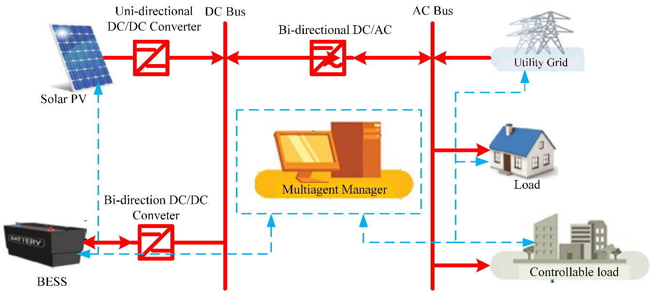
Figure 1. Grid-connected multiagent renewable power system
- Butterworth Inertia Weight Particle Swarm Optimization (BIWPSO)
PSO is a random population, swarm-inspired optimizing method that models the rules guiding the birds' flocking and swarm of fish. A swarm agent stands for a solution that can be described in terms of its positional change with velocity. The agent’s position and velocity changes from the previous to the present are updated accordingly. An individual agent is associated with its best value (pbest) and its best value in the pbests group (gbest). The mathematical expression for velocity and position is as [29]:
| 
| (1) |
Where denotes updated velocity at iteration k+1 for agents i and j,
  is the current velocity at iteration k for agents i and j, w is the inertia weight,
  and
and  are acceleration coefficients, The
  and are
  are the random numbers 1 and 2 respectively,
  is iteration k current position for agent i and j respectively, agents i and j personal best position is
  and the gbest of the group is
  . The positional update is expressed as follows:
| 
| (2) |
The inertia weight function is:
| 
| (3) |
Where  is the maximum weight and
  is the minimum weight,
  is maximum iteration, and
  denotes the current iteration. The effective handling of the problem of exploitation and the need to strike a balance between the exploration and exploitation phases of PSO in reducing the trapping at the local minima, demands the application of the Butterworth filter response equation, which produces a good balance between the upper and lower threshold is adopted to determine the inertia weight sequence. The Butterworth filter response equation is expressed as [30]:
| 
| (4) |
Where f is the calculation frequency, fc is the cut-off frequency, and Vin denotes the input voltage, Vout denotes the output voltage, n denotes the number of filter’s elements. The inertia equation is modified to capture the characteristics function of the filter equation and expressed as:
| 
| (5) |
 is set to be one-third of the maximum number of iterations,
  is 10,
  is 0.5, while
  is 0.4
- Modeling of photovoltaic and ESS
The decentralized zonal allocation of the PV/ESS system is modeled on the distribution network to minimize the network voltage deviation and power loss. PV/ESS injects its power into the distribution network and stores excess energy during the off-peak condition. The AC/DC and DC/DC power converters connect both AC and DC buses for power injection to the load.
- Photovoltaic System
The PV-generated power is expressed as [31] :
| 
| (6) |
Where PV surface irradiance is G measured in (W/m2), The PV nominal power is  with standard radiation rated as 1000W/m2,
  is the PV module temperature coefficient,
  is the cell temperature and
  is the reference temperature.
- Battery modeling
The power deficit of the grid-connected system due to the demand variation and fluctuation in renewable photovoltaic sources is managed using the ESS. In considering the random behavior of the PV source, the battery is constantly in charging mode in the system except when delivering power during deficiency. The state of charge (SOC) is defined on the following modes:
- The charging mode, when the grid injects power plus the power from the PV (Network power), is greater than the network load demand. It is assumed that the efficiency of the inverter is 0.95. The charged state of the battery is expressed as:
| 
| (7) |
Where,  and
and  are the battery power at time
  and
and  .
.  is the network power and
  is the network load demand.
- The discharging mode is when the network load demand exceeds the grid-injected power plus the power from the PV (Network power). It is assumed that the efficiency of the inverter is 0.95. The charged state of the battery is expressed as:
| 
| (8) |
Where,  and
and  are the battery power at time
  and
and  .
.  stands for network power and
  denotes network load demand.
- Problem Formulation
This study considered minimizing the voltage deviation and the power loss as the objective functions. The sizing and location of the PV/ESS are the decision variables. The optimized variables were fed into the decentralized multiagent system for the holistic distribution power management system. The two objective functions of the study are presented.
- Power loss
The power loss minimization is defined and calculated as [32]:
| 
| (9) |
Where the resistance between node  and
and  is
is  ,
,  and
and  are the branch active and reactive power, and
  denotes the terminal voltage.
- Voltage deviation
Any improvement in the voltage profile consequently results in better voltage deviation on network buses. The voltage deviation and the second objective function are expressed and calculated as [33][34]:
| 
| (10) |
| 
| (11) |
Where  is the voltage at
  bus,
bus,  is the buses average voltage and
  is the number of the buses.
- Constraint
The following constraints are considered in work: the power equations are balanced, fulfilled, and expressed as follows:
| 
| (12) |
| 
| (13) |
Where  = 1,2,…,
 . The voltage at each bus and the generator bus is maintained within the statutory limit. The adopted value ranges between 0.95 and 1.05:
| 
| (14) |
The capacity of the renewable generation is also maintained between the maximum and the minimum:
| 
| (15) |
- Implementation procedure for Butterworth inertia weight particle swarm optimization
The implementation procedures for BIWPSO for siting and sizing the PV/ESS system and optimizing the network parameters for the MAS system are presented as follows:
Step 1: Initialize the problem statement:
The objective function(s), decision variables, and constraints of the optimization problem are defined, which is the minimization of power loss and voltage deviation. The sizing and location of the PV/ESS system are the decision variables; all constraints are well-defined.
Step 2: Initialize the BIWPSO parameters:
The maximum iterations (max_iter) is fixed at 200, the population size (pop_size) is 100, the cognitive and social learning factors (C1, C2) are set to 2, and the maximum and minimum inertia weight values (w_max, w_min) are set to 0.5 and 0.4, respectively, based on the BIWPSO Equation (5).
Step 3: Initial population is generated:
The initial population of random solutions for the decision variables within the feasible range is generated.
Step 4: Evaluate the population fitness function:
The fitness of each solution in the population using the backward/forward sweep load flow method is evaluated using the objective function defined in Step 1.
Step 5: Initialize the personal best and global best positions:
The personal best positions of each particle as the initial solutions, and the global best position as the solution with the highest fitness value set
Step 6: Main loop:
Repeat steps 7-11 until the stopping criteria are met.
Step 7: The personal best and global best positions are updated:
Update the personal best positions of each particle based on the fitness value of the current solution. Update the global best position based on the fitness value of all solutions in the population. Then, the best performance indicators of the system are finally discovered.
Step 8: The velocity and position of each particle are updated
Each particle's velocity is updated based on the current velocity, the cognitive and social learning factors, and the distance to the personal best and global best positions. The position of each particle is updated based on the current position and the velocity. Ensure the updated position is within the feasible range.
Step 9: Evaluate the fitness of the new population:
Evaluate the fitness of each solution in the new population using the backward/forward sweep load flow method using the objective function defined in Step 1.
Step 10: Check the stopping criteria:
Exit the loop if the convergence threshold has been met, meaning no better convergence achieved within the last highest iteration number.
Step 11: Output the optimal solution:
Output the optimal solution and its fitness value based on the global best position. Using BIWPSO, the output optimal solution would include the sizing and location of PV/ESS and minimize power loss and voltage deviation while satisfying the power balance equation and constraints.
- Multiagent Power Management Strategy
The proposed MAS structure consists of a zone agent ( ), load agent (
 ) and generation agent (
 ). The
  represents the central agent of the delineated zone and can exchange information with other agents, such as the zonal generation and load agents and other zonal agents. The ZA directs the decision to preserve the zonal disparity in load and power generation as determined by the power flow analysis. The major task of GA is the monitoring and adjustment of the power output of its distributed generation (DG) to match demand within its
  . Its task also involves updating the
  whenever generation changes occur due to weather variations or alterations in DG connection status. The load agent updates the
  with changes in the buses connected with load demands.
The zones are produced by a partitioning approach using the line current. This is targeted at electrically grouping the buses closest to each other to a specific DG, and the zonal buses are assigned based on the line current. Individual zone is created using the following assumptions: a zone must consist of at least one DG, the location of DGs are optimized using the proposed butterworth Inertial weight PSO, and the zones are created for a system once, according to line current and the optimized placement of the DGs. As power flow is executed and updated, the MAS manages the power output of the DGs until the power mismatch in generation and demand in the zone is matched. The proposed MAS power management structure for grid-connected photovoltaic/ESS is shown in Figure 2.
Once the DGs powers are sent during the power flow analysis,  monitors the variation in the generation and demand occurrence within its zone. In the occurrence of changes, the zonal power is adjusted to absorb the change automatically. The process persists until MAS takes the necessary action to preserve the variation between the generation and demand in the zone to match the value obtained from the power flow calculation.
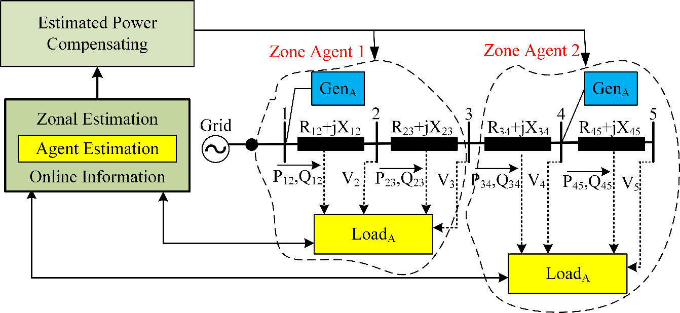
Figure 2. The proposed MAS power management structure for grid-tied PV/ESS system
The operation sequence for the agents is detailed as follows: let the variation between generation and demand within zone  as a result of variation in load demand at bus
  , be
, be  . Then,
 sends an information to
  , which includes the value of variation in demand,
 requests from
  to change its DG generation,
 determines whether to increase or decrease generation and determines the size of
  to handle the change effectively,
  is capable of taking up the variation if power generated does not violate the network constraints outside its statutory limits. The effects of power-generated variation on voltage is then evaluated,
  replies to
  with one of the following messages:
- Agree response, which includes the estimated power that
 is capable of taking up based on
- Inform response, that includes the estimated power that
 can take up within the network constraints.
 - Reject response when
 refuses the request due to
  operating at its upper limit.
 obtains a response from
  , and if the response is Agree, the process is terminated. Otherwise, the process goes to the next step.
- The neighboring zonal DGs are called upon to take part in accommodating the load demand change in Zone
 . The closest zones to ith zone are firstly selected to minimize power loss.
  put up a proposal signal to neighboring zones agents (NZAs). If NZA can accommodate the demand, then the network accommodates the change, and the sequence will be terminated. Else,
  s ask DGs agents (NGAs) to determine their individual strength in handling the required power. The NGAs determine the capacity of their DGs to take up the change by following the conditions stated in step (3) to step (4) and the reply finally sent to their
  .
. - A reply proposal from NZAs is sent to
 .
.  ranks the received information proposals based on closest neighbors to proceeds as follows:
 conveys an acceptance proposal to the closest
  , then terminates the operation if it is determined that closest
  is able to accommodate the required power demand.
 sends an acceptance proposal to the closest
  , it also checks the subsequent proposal if it shows that the closest
  is able accommodate only a part needed power. The closest neighboring zone supplies remaining power demand; then the operation is terminated. Otherwise,
  monitors the subsequent proposal till the
  request is satisfied.
 looks for power needed in the subsequent
  , if it is shown that the closest
  is unable to contribute to the operation.
The flowchart for the proposed MAS power management structure for grid-tied PV/EES system is shown in Figure 3. The optimized distribution network parameters are fed into the multiagent system to achieve the best performance of MAS. It is achieved by modifying inertial weight in particle swarm optimization, to follow a Butterworth filtering curve for holistic space search and improved convergence.
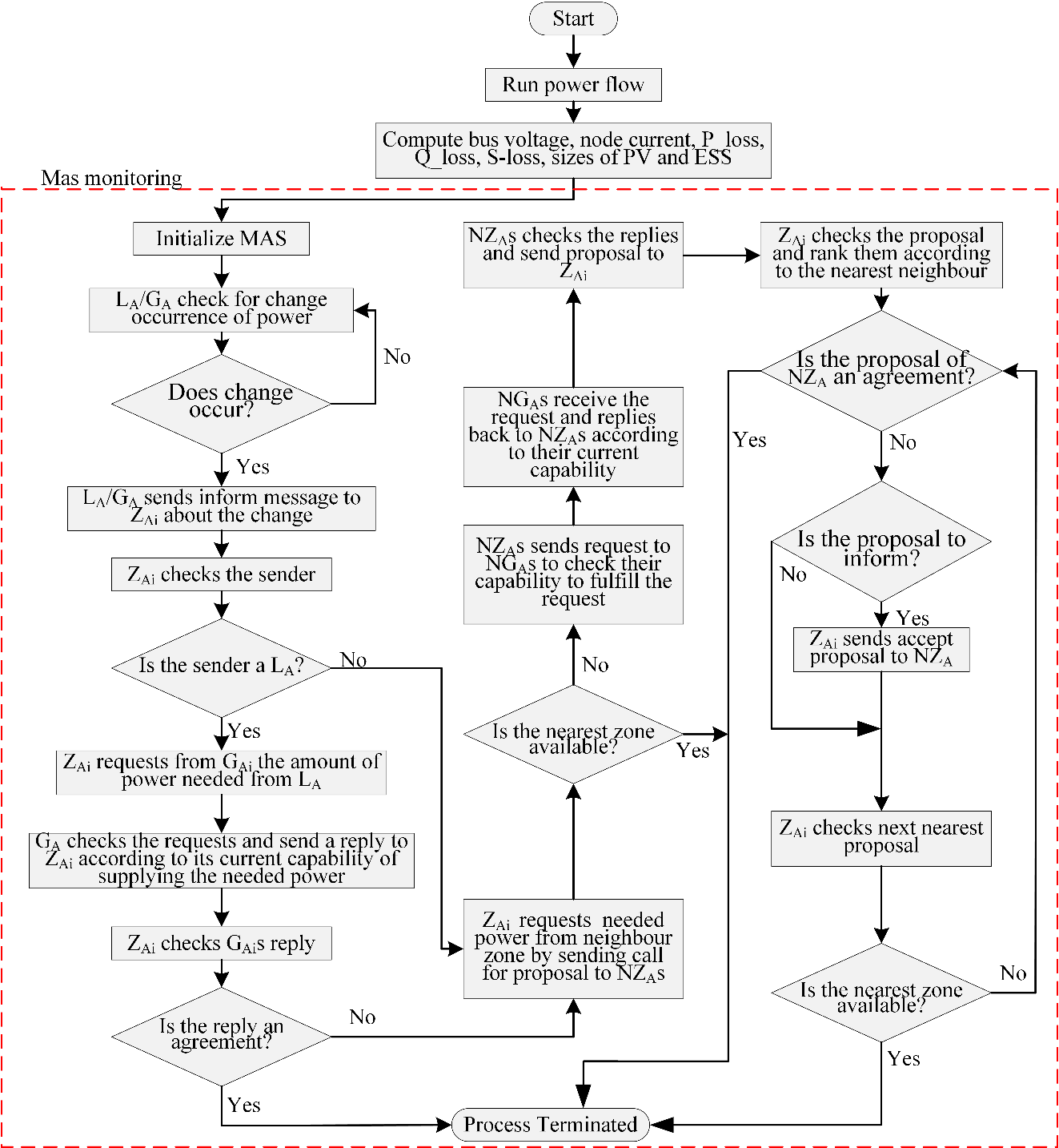
Figure 3. The flowchart for the proposed MAS power management structure for grid-connected PV/EES
- RESULTS AND DISCUSSION
Simulation and analysis of the proposed model were implemented to confirm the validity of the research work's effectiveness using IEEE 33-bus distribution. The network information of the thirty-three-bus network is shown in Figure 4. The network real power is 3.72 MW and reactive power is 2.3MVAr. The substation base power is 100MVA at 12.66kV [35].
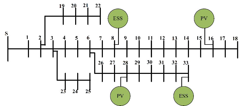
Figure 4. IEEE 33 – Bus distribution system
The results are analyzed and presented using BIWPSO algorithms to determine the voltage magnitude of each bus, power loss, size, and location of RES for optimality. The results of BIWPSO at full load with RES injection are shown in Table 1. The effects of only PV and PV with BESS are investigated.
Table 1. Results of voltage and loss for IEEE 33 – bus distribution
Item | Without RES | With RES |
PV | PV/BESS |
Power loss (kW) | 243.60 | 123.96 | 76.53 |
Loss reduction (%) | -- | 49.11 | 68.58 |
Min. voltage | 0.9131 | 0.9307 | 0.9315 |
Max. voltage | 0.9965 | 0.9970 | 1.0090 |
Node no | -- | 6 | 29 |
Power Factor | -- | Unity | Unity |
Size(kW) | -- | 2046 | 2551 |
Feeder voltage deviation (pu) | 1.7009 | 0.1709 | 0.2389 |
Voltage Improvement. (%) | -- | 85.95 | 89.95 |
The optimal location and capacity using BWIPSO are evaluated. The optimal location for the PV installation is on bus 6, with an estimated capacity of 2046kW. Power loss was reduced by 49.11%, from 243.60 kW to 123.96 kW. Bus 18, with the lowest voltage value increased to 0.9307 p.u from its initial value of 0.9131 p.u.. The voltage magnitude of different installations of RES is demonstrated as shown in Figure 5. The figure visualizes the impact of one PV installation and PV/BESS on the network.
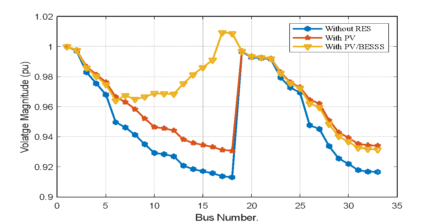
Figure 5. IEEE 33-Bus distribution system voltage magnitude with PV, PV and BESS
A comparison of results obtained with ordinary PSO with what is obtainable using BIWPSO is shown in Table 2. The BIWPSO reflects an improved performance in network voltage and power loss.
Table 2. Results comparison for PV/BESS placement on IEEE 33-Bus system
Item | Initial | PSO | BIWPSO |
Power loss (kW) | 243.60 | 84.23 | 76.53 |
Loss reduction (%) | -- | 65.42 | 68.58 |
Min. voltage | 0.9131 | 0.9635 | 0.9315 |
Max. voltage | 0.9965 | 1.0021 | 1.0090 |
Node no | -- | 30 | 29 |
Power Factor | -- | Unity | Unity |
Size(kW) | -- | 2555 | 2551 |
Feeder voltage deviation (pu) | 1.7009 | 0.2008 | 0.2389 |
Voltage Improvement. (%) | -- | 88.19 | 89.95 |
The convergence characteristics of the proposed technique is compared with the conventional PSO, as demonstrated in Figure 6. The BIWPSO approach shows less convergence tolerance and faster convergence, which implies the method is efficient in obtaining the best network performance within a shorter duration.
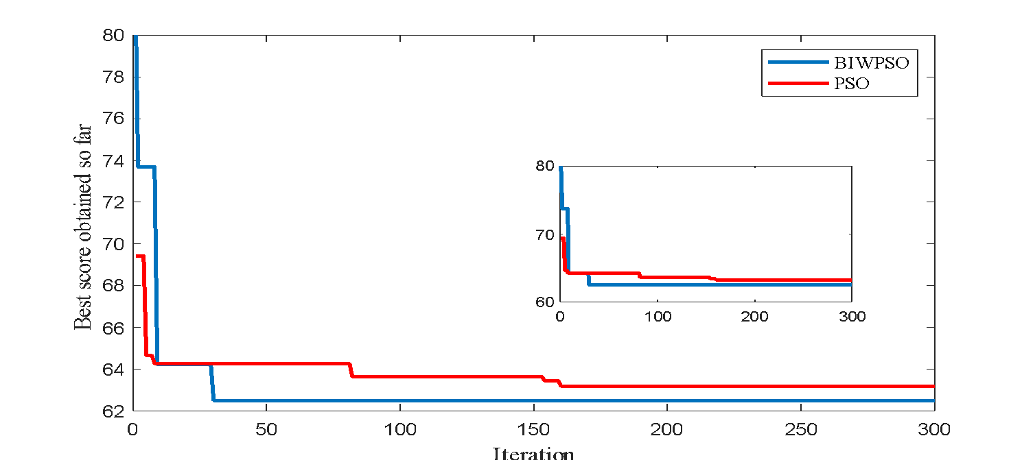
Figure 6. Convergence curve on IEEE 33-Bus distribution system
The multiagent system distribution management technique is employed on the IEEE 33-Bus radial distribution network with optimal parameters through the BIWPSO. The possible generation and load variations scenarios as interactions in their different zones were simulated. The hourly output power profile of the photovoltaic renewable source is shown in Figure 7. The network renewable source and ESS harmoniously respond to network demand based on the agent interaction to achieve a daily voltage profile within the statutory limit, as shown in Figure 8.
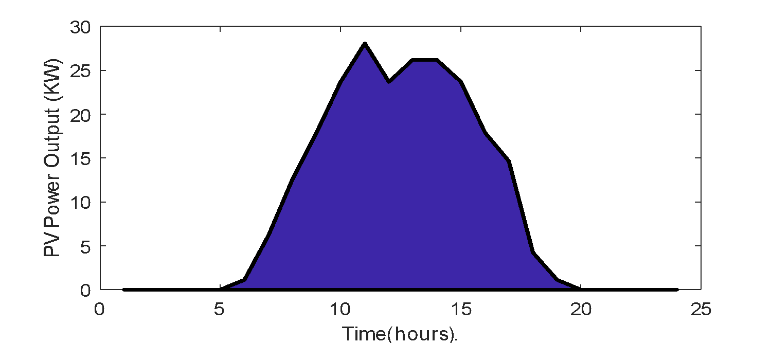
Figure 7. The hourly output power profile of the photovoltaic power generation
The PV renewable generation and the battery energy storage system capacities, already evaluated through an optimization procedure, are now enhanced for improved performance through the MAS coordinating technique. It considers a time series over a daily simulation period of 24 hours. There is an improvement in the voltage with the distribution agent's interaction compared to the case without distribution agents, as shown in Figure 8. The capacity and location of the generation agents  and
and  components are detailed in Table 3. The percentage of voltage improvement is 86.52, and that of power loss reduction is 68.43.
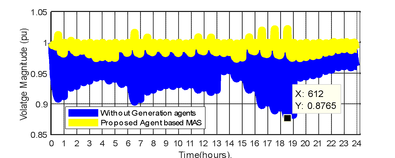
Figure 8. The daily voltage profile with the integration of two-generation agents
Table 3. Results for integration of two-generation agents on IEEE 33 – bus distribution system
Item | Without Generation agents ( and and  ) ) | With Generation agents ( and and  ) ) |

|
| PV |
Size(KVA)/PF |
| 2585/1 |
Bus no |
| 6 |

|
| BESS |
Size(KVA) |
| 2593/1 |
Bus no |
| 27 |
Total losses (kW) | 4587.72 | 1448.34 |
Loss reduction (%) | … | 68.43 |
Min. voltage | 0.8765 | 0.9710 |
Max. voltage | 1.0000 | 1.0230 |
Feeder voltage deviation (pu) | 1.4548 | 0.1961 |
Voltage Improvement. (%) | … | 86.52 |
The BESS in generation agent 2 ( ) backs up the network grid when the PV in generation agent 1 cannot meet the load demand from the load agents on the network during the day. It occurs when the load current (
 ) is more significant than (
 ). Figure 9 shows the BESS power injection to the grid at 03.00 hour with a discharging SOC from 200kA to 181kA. The network charging current returned positive from 04.00 hour; the PV then assumes power injection, and BESS continues being charged up. Another battery discharge occurred at 20.00 hour. Figure 10 shows the charging and discharging current of the BESS for the day.
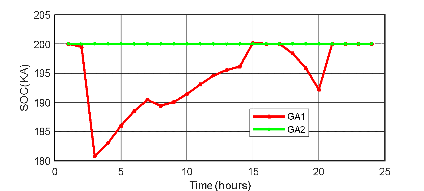
Figure 9. The battery state of charge for  and
and 
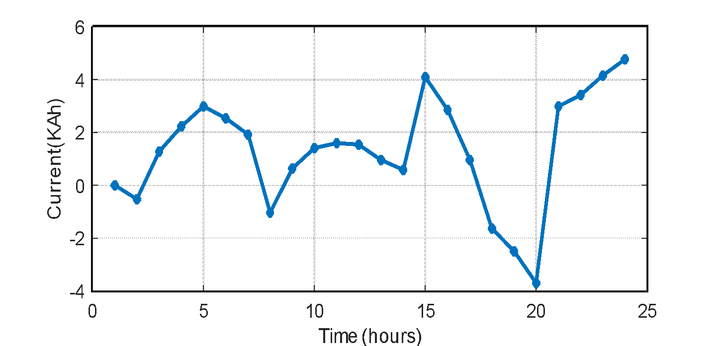
Figure 10. The charging and discharging current of the ESS
A comparison of results obtained from the MAS distribution coordinating technique with the proposed BIWPSO shows that the MAS technique is a way of achieving further network performance improvement after the use of metaheuristic methods, as shown in Table 4.
Table 4. Results comparison for MAS approach and BIWPSO on IEEE 33 – bus distribution system
Item | Without MAS and BIWPSO | With MAS | With only BIWPSO |
GA1 |
| PV | PV |
Size(KVA)/PF |
| 2585/1 | 2585/1 |
Bus no |
| 6 | 6 |
GA2 |
| BESS |
|
Size(KVA) |
| 2593/1 | 2593/1 |
Bus no |
| 27 | 27 |
Total losses (kW) | 4587.72 | 1448.34 | 1533.2 |
Loss reduction (%) | … | 68.43 | 66.58 |
Min. voltage | 0.8765 | 0.9710 | 0.9653 |
Max. voltage | 1.0000 | 1.0230 | 1.0159 |
Feeder voltage deviation (pu) | 1.4548 | 0.1961 | 0.2084 |
Voltage Improvement. (%) | … | 86.52 | 85.67 |
- CONCLUSION
This paper presented PV/Battery ESS system grid-connected network to reduce the deviation in voltage and power loss. The Butterworth inertial weight PSO determines the installation of the PV/ESS system at the optimal location and size, along with other network parameters. The inertial weight of the optimization technique is patterned along the Butterworth filtering curve for holistic space search and improved convergence. The results show superiority when compared to traditional PSO. The power loss reduction of 68.58% and improvement in voltage deviation of 89.95% are achieved with the BIWPSO compared to 65.42% power loss reduction and 88.19% voltage deviation improvement achieved in traditional PSO. The proposed technique had a faster convergence in less than 40 iterations. Intelligent agents then coordinate the grid-connected network. It is structured into a zone, generation and load agents for updating the load and power injection at different network buses. This is achieved over a daily multi-period network simulation. The proposed technique is applied to the IEEE 33- Bus distribution network, the network analysis and parameters assumes a balance system of power network. The results show the impact of the renewable battery system on power loss, network voltage, voltage deviation, and voltage profile over 24 hours. The simulation shows that installing the PV/ESS system leads to achieving the least voltage deviation and loss on the network. The decentralized multiagent coordination technique achieves voltage within the statutory limit over a daily simulation period despite load demand and generation variations. The deployment of the developed power management strategy will help the utilities to control the voltage and minimize excessive losses inherent in active distribution systems. Therefore, the network operator is enhanced with logical methods for decision-making in innovative modern power networks. This research is recommended to utility companies in electric power system operations and planning, such as national transmission and distribution companies. Future work could consider the cost implications of power loss reduction and energy saving using the proposed method and unbalanced network analysis.
REFERENCES
- A. U. Adoghe, T. M. Adeyemi-Kayode, V. Oguntosin, and I. I. Amahia, “Performance evaluation of the prospects and challenges of effective power generation and distribution in Nigeria,” Heliyon, vol. 9, no. 3, p. 441, 2023, https://doi.org/10.1016/j.heliyon.2023.e14416.
- N. Kanagaraj, M. Vijayakumar, M. Ramasamy, and O. Aldosari, “Energy Management and Power Quality Improvement of Hybrid Renewable Energy Generation System Using Coordinated Control Scheme,” IEEE Access, vol. 11, no. June, pp. 93254–93267, 2023, https://doi.org/10.1109/ACCESS.2023.3299035.
- R. Debnath, V. Mittal, and A. Jindal, “A review of challenges from increasing renewable generation in the Indian Power Sector: Way forward for Electricity (Amendment) Bill 2020,” Energy Environ., vol. 33, no. 1, pp. 3–40, 2022, https://doi.org/10.1177/0958305X20986246.
- S. Kawambwa and D. Mnyanghwalo, “A multi-agent-based symbiotic organism search algorithm for DG coordination in electrical distribution networks,” J. Electr. Syst. Inf. Technol., vol. 10, no. 1, 2023, https://doi.org/10.1186/s43067-023-00072-7.
- W. Shi, D. Zhang, X. Han, X. Wang, T. Pu and W. Chen, "Coordinated operation of active distribution network, networked microgrids, and electric vehicle: A multi-agent PPO optimization method," in CSEE Journal of Power and Energy Systems, 2023, https://doi.org/10.17775/CSEEJPES.2022.05640.
- S. S. Ghazimirsaeid, M. S. Jonban, M. W. Mudiyanselage, M. Marzband, J. L. R. Martinez, and A. Abusorrah, “Multi-agent-based energy management of multiple grid-connected green buildings,” J. Build. Eng., vol. 74, no. May, p. 106866, 2023, https://doi.org/10.1016/j.jobe.2023.106866.
- A. Al-Hinai and H. Haes Alhelou, “A multi-agent system for distribution network restoration in future smart grids,” Energy Reports, vol. 7, pp. 8083–8090, 2021, https://doi.org/10.1016/j.egyr.2021.08.186.
- T. Senjyu, Y. Miyazato, A. Yona, N. Urasaki, and T. Funabashi, “Optimal distribution voltage control and coordination with distributed generation,” IEEE Trans. Power Deliv., vol. 23, no. 2, pp. 1236–1242, 2008, https://doi.org/10.1109/TPWRD.2007.908816.
- P. N. Vovos, A. E. Kiprakis, A. R. Wallace, and G. P. Harrison, “Centralized and distributed voltage control: Impact on distributed generation penetration,” IEEE Trans. Power Syst., vol. 22, no. 1, pp. 476–483, 2007, https://doi.org/10.1109/TPWRS.2006.888982.
- B. Zhang, D. Cao, W. Hu, A. M. Y. M. Ghias, and Z. Chen, “Physics-Informed Multi-Agent deep reinforcement learning enabled distributed voltage control for active distribution network using PV inverters,” Int. J. Electr. Power Energy Syst., vol. 155, no. PB, p. 109641, 2024, https://doi.org/10.1016/j.ijepes.2023.109641.
- A. Y. Hatata, E. O. Hasan, M. A. Alghassab, and B. E. Sedhom, “Centralized Control Method for Voltage Coordination Challenges With OLTC and D-STATCOM in Smart Distribution Networks Based IoT Communication Protocol,” IEEE Access, vol. 11, no. February, pp. 11903–11922, 2023, https://doi.org/10.1109/ACCESS.2023.3242236.
- M. Pérez Hernández, A. Puchkova, and A. K. Parlikad, “Multi-Agent Learning of Asset Maintenance Plans through Localised Subnetworks,” Eng. Appl. Artif. Intell., vol. 127, no. PB, p. 107362, 2024, https://doi.org/10.1016/j.engappai.2023.107362.
- H. Lan, S. Wen, Q. Fu, D. C. Yu, and L. Zhang, “Modeling analysis and improvement of power loss in microgrid,” Math. Probl. Eng., vol. 2015, 2015, https://doi.org/10.1155/2015/493560.
- E. Unamuno and J. A. Barrena, “Hybrid ac/dc microgrids - Part I: Review and classification of topologies,” Renew. Sustain. Energy Rev., vol. 52, pp. 1251–1259, 2015, https://doi.org/10.1016/j.rser.2015.07.194.
- Y. Yoldaş, A. Önen, S. M. Muyeen, A. V. Vasilakos, and İ. Alan, “Enhancing smart grid with microgrids: Challenges and opportunities,” Renew. Sustain. Energy Rev., vol. 72, no. January, pp. 205–214, 2017, https://doi.org/10.1016/j.rser.2017.01.064.
- M. S. Rahman, M. A. Mahmud, H. R. Pota, and M. J. Hossain, “Distributed multi-agent scheme for reactive power management with renewable energy,” Energy Convers. Manag., vol. 88, pp. 573–581, 2014, https://doi.org/10.1016/j.enconman.2014.09.002.
- H. K. Kang, I. Y. Chung, and S. Il Moon, “Voltage control method using distributed generators based on a multi-agent system,” Energies, vol. 8, no. 12, pp. 14009–14025, 2015, https://doi.org/10.3390/en81212411.
- E. Shirazi and S. Jadid, “A multiagent design for self-healing in electric power distribution systems,” Electr. Power Syst. Res., vol. 171, no. February, pp. 230–239, 2019, https://doi.org/10.1016/j.epsr.2019.02.025.
- E. Abbaspour, B. Fani, E. Heydarian-Forushani, and A. Al-Sumaiti, “A multi-agent based protection in distribution networks including distributed generations,” Energy Reports, vol. 8, pp. 163–174, 2022, https://doi.org/10.1016/j.egyr.2022.10.394.
- E. Xydas, C. Marmaras, and L. M. Cipcigan, “A multi-agent based scheduling algorithm for adaptive electric vehicles charging,” Appl. Energy, vol. 177, pp. 354–365, 2016, https://doi.org/10.1016/j.apenergy.2016.05.034.
- Z. Liu, C. Su, H. K. Hoidalen, and Z. Chen, “A multiagent system-based protection and control scheme for distribution system with distributed-generation integration,” IEEE Trans. Power Deliv., vol. 32, no. 1, pp. 536–545, 2017, https://doi.org/10.1109/TPWRD.2016.2585579.
- K. Mistry, “MSFL based determination of optimal size and location of distributed generation in radial distribution system,” Int. Conf. Electr. Electron. Optim. Tech. ICEEOT 2016, pp. 530–535, 2016, https://doi.org/10.1109/ICEEOT.2016.7755670.
- M. A. Tolba, V. N. Tulsky, and A. A. Z. Diab, “Optimal sitting and sizing of renewable distributed generations in distribution networks using a hybrid PSOGSA optimization algorithm,” Conf. Proc. - 2017 17th IEEE Int. Conf. Environ. Electr. Eng. 2017 1st IEEE Ind. Commer. Power Syst. Eur. EEEIC / I CPS Eur. 2017, 2017, https://doi.org/10.1109/EEEIC.2017.7977441.
- V. N. TUL’SKY, M. A. TOLBA, and A. S. VANIN, “Optimal Capacitor Allocations and Sizing in Radial Distribution Networks Using a Novel Hybrid Particle Swarm Optimization Algorithm,” Elektrichestvo, no. 6, pp. 16–23, 2017, https://doi.org/10.24160/0013-5380-2017-6-16-23.
- P. A. Gkaidatzis, A. S. Bouhouras, D. I. Doukas, K. I. Sgouras, and D. P. Labridis, “Application and evaluation of UPSO to ODGP in radial Distribution Networks,” Int. Conf. Eur. Energy Mark. EEM, vol. 2016-July, 2016, https://doi.org/10.1109/EEM.2016.7521223.
- M. Bechouat, M. Sedraoui, Y. Soufi, L. Yousfi, A. Borni, and S. Kahla, “Particle swarm optimization backstepping controller for a grid-connected PV/Wind Hybrid system,” J. Eng. Sci. Technol. Rev., vol. 10, no. 1, pp. 91–99, 2017, https://doi.org/10.25103/jestr.101.13.
- M. Marzband, M. Ghadimi, A. Sumper, and J. L. Domínguez-García, “Experimental validation of a real-time energy management system using multi-period gravitational search algorithm for microgrids in islanded mode,” Appl. Energy, vol. 128, pp. 164–174, 2014, https://doi.org/10.1016/j.apenergy.2014.04.056.
- M. H. Moradi and M. Abedini, “A combination of genetic algorithm and particle swarm optimization for optimal DG location and sizing in distribution systems,” Int. J. Electr. Power Energy Syst., vol. 34, no. 1, pp. 66–74, 2012, https://doi.org/10.1016/j.ijepes.2011.08.023.
- T. S. Tawfeek, A. H. Ahmed, and S. Hasan, “Analytical and particle swarm optimization algorithms for optimal allocation of four different distributed generation types in radial distribution networks,” Energy Procedia, vol. 153, pp. 86–94, 2018, https://doi.org/10.1016/j.egypro.2018.10.030.
- X. Zhu and H. Wang, “A new inertia weight control strategy for particle swarm optimization,” AIP Conf. Proc., vol. 1955, 2018, https://doi.org/10.1063/1.5033759.
- O. Olatunde, M. Y. Hassan, M. P. Abdullah, and H. A. Rahman, “Real-time multiperiod voltage control algorithm with OLTC and switched capacitors for smart distribution networks in the presence of energy storage system,” Int. Trans. Electr. Energy Syst., no. March, pp. 1–21, 2020, https://doi.org/10.1002/2050-7038.12475.
- A. Hussain, S. M. Arif, M. Aslam, and S. D. A. Shah, “Optimal siting and sizing of tri-generation equipment for developing an autonomous community microgrid considering uncertainties,” Sustain. Cities Soc., vol. 32, no. September 2016, pp. 318–330, 2017, https://doi.org/10.1016/j.scs.2017.04.004.
- T. Kerdphol, K. Fuji, Y. Mitani, M. Watanabe, and Y. Qudaih, “Optimization of a battery energy storage system using particle swarm optimization for stand-alone microgrids,” Int. J. Electr. Power Energy Syst., vol. 81, pp. 32–39, 2016, https://doi.org/10.1016/j.ijepes.2016.02.006.
- A. Chamba, C. Barrera-Singaña, and H. Arcos, “Optimal Reactive Power Dispatch in Electric Transmission Systems Using the Multi-Agent Model with Volt-VAR Control,” Energies, vol. 16, no. 13, pp. 1–25, 2023, https://doi.org/10.3390/en16135004.
- M. javad Aliabadi and M. Radmehr, “Optimization of hybrid renewable energy system in radial distribution networks considering uncertainty using meta-heuristic crow search algorithm,” Appl. Soft Comput., vol. 107, p. 107384, 2021, https://doi.org/10.1016/j.asoc.2021.107384.
AUTHOR BIOGRAPHY

| Oladepo Olatunde is a lecturer and researcher in the Department of Electrical and Electronic Engineering, Osun state University, Osogbo, Nigeria. He holds Master’s degree in Electrical and Electronics Engineering from The Federal University of Technology, Akure, Nigeria (2012). He bagged Ph.D in Electrical Engineering at Universiti Teknologi Malaysia, Johor Bahru, Malaysia (2021). He is a registered member of the Council for the Regulation of Engineering in Nigeria (COREN) and can be contacted on ooladepo@yahoo.com. |
|
|

| Ugwute Francis Okoro is an Electrical Engineer at National Control Centre, Transmission Company of Nigeria. He holds a Bachelor Degree in Electrical and Electronic Engineering from Kwara State University Malate, Nigeria. He is a fellow of Nigerian Society of Engineers, member Nigerian Institute of Electrical and Electronic Engineers and a registered engineer with the Council for the Regulation of Engineering in Nigeria (COREN). His area of interest include power system analysis, smart grid and renewable generation. |
|
|

| Awofolaju Tolulope Tola is a Lecturer at the department of Electrical and Electronic Engineering, Osun State University, Osogbo, Nigeria. She is a Registered Engineer with Council for the regulation of Engineering in Nigeria (COREN), Member, Nigerian Society of Engineers and Member, Association of Professional Women Engineers of Nigeria. She bagged Master of Engineering (M.Eng) in Electrical & Electronics Engineering (Communication Engineering) at The Federal University of Technology, Akure, Nigeria and Bachelor of Technology (B.Tech) degree in Electronic and Electrical Engineering at Ladoke Akintola University of Technology, Ogbomoso, Nigeria. She holds PhD communication Engineering. Her area of interest include wireless communication, cognitive radio, 5G, radio frequency spectrum to mention a few. |
Multiagent based Power Management for Grid-connected Photovoltaic Source Using the Optimized Network Parameters From Butterworth Inertia Weight Particle Swarm Optimization (Oladepo Olatunde)