Buletin Ilmiah Sarjana Teknik Elektro ISSN: 2685-9572
Implementation of Kalman Filter on Pid Control System for DC Motor Under Noisy Condition
Nurman Setiawan 1,*, Wahyu Caesarendra 2,3, Rania Majdoubi 4
1 Department of Electrical Engineering Education, Universitas Negeri Yogyakarta, Indonesia
2 Faculty of Integrated Technologies, Universiti Brunei Darussalam, Jalan Tungku Link, Gadong, BE1410,
Brunei Darussalam
3 Faculty of Mechanical Engineering, Opole University of Technology, 76 Proszkowska St, 45-758, Opole, Poland
4 SETIME Laboratory, faculty of sciences, ibn tofail University, Kenitra, Morocco
ARTICLE INFORMATION |
| ABSTRACT |
Article history: Received 26 July 2024 Revised 26 August 2024 Published 24 September 2024 |
| 
DC motors are actuators that are widely used in various fields. The reason is that DC motors are easy to control, high torque at low speed, and fast response. Angular velocity of DC motor is regulated automatically by using certain controls method, the most commonly used of which is PID control. The performance of the control system decreases in the presence of disturbance or noise. The presence of noise give has negative impacts such as instability in control response, decreased accuracy, and difficulty in tuning PID gain. The most common disturbance comes from the inaccuracy data due to measurement noise and process noise. In this study, the Kalman filter is proposed as a state estimator to reduce the influence of noise, both process noise and measurement noise. The Kalman filter provides an optimal estimate of the angular velocity of DC motor by minimizing the mean squared error. The estimated angular velocity from Kalman Filter is utilized as input for PID control. Simulation results show that the Kalman filter is capable to reduces the influence of measurement noise. In nominal condition, PID control give an Integral Absolute Error (IAE) of 344.56. Under noisy condition, PID control (without Kalman filter) has an IAE of 517.27, while Kalman filter-based PID control has an IAE of 345.25. The IAE reduction of 99.6% indicates that the proposed control system effectively minimizes errors, resulting in better performance and stability. |
Keywords: Kalman Filter; PID Control; Noise; DC Motor; Stability |
Corresponding Author: Nurman Setiawan, Department of Electrical Engineering Education, Universitas Negeri Yogyakarta, Indonesia. Email: nurman.setiawan@uny.ac.id |
This work is licensed under a Creative Commons Attribution-Share Alike 4.0 
|
Document Citation: N. Setiawan, W. Caesarendra, and R. Majdoubi, “Battery Usage Monitoring System Internet of Things-Based Electric Cars (IoT) and Radio Telemetry,” Buletin Ilmiah Sarjana Teknik Elektro, vol. 6, no. 3, pp. 271–280, 2024, DOI: 10.12928/biste.v6i3.11524. |
INTRODUCTION
DC motors are commonly used actuators in both the industrial and academic field. DC motors have a number of advantages that make them remain relevant in various applications. Some of the advantages are ease of velocity regulation, high torque at low speeds, fast response and high efficiency [1]. In the industrial field, DC motors are widely used to drive industrial equipment such as conveyors, robots and other automation equipment. Meanwhile, in the academic field, DC motors are used for research, development and prototyping.
DC motors require a controller so it can move as desired. The most widely used controller is PID (Proportional-Integral-Derivative). PID control is chosen for some reason, such as fast response, robust against load changes, ease of setting its performance through parameters of  ,
,  , and
, and  [2][3]. There are various tuning method of PID parameter that have been developed, such as Ziegler-Nichols [4], iterative feedback [6],[5], fuzzy logic system [7], genetic alghorithm [8][9], Particle Swarm Optimization [10], and ant colony optimization [11]. Zeigler Nichols and iterative feedback tuning are simple and widely used methods for tuning PID controllers. However, the presence of noise can affect the tuning process and the accuracy of the final parameters. Zeigler Nichols and iterative feedback are simple and widely used method for PID controller tuning. however, the noise can affect the tuning process and the accuracy of the final parameters. Meanwhile Fuzzy Logic Systems and Genetic Algorithms are generally more robust and effective in noisy environments due to their ability to handle uncertainties and adapt to changing conditions. But, these method has a complicated design and is computationally intensive.
PID control works properly if the DC motor is in ideal conditions. However, its performance will decrease if the noises take place. Noise can be classified into two primary categories: measurement noise and process noise. Measurement noise refers to random errors or disturbances that affect the accuracy of sensor readings in a system. It is typically random, often modeled as Gaussian (white) noise with a zero mean, and can stem from sources such as sensor inaccuracies, electrical interference, or quantization errors [12][13]. This type of noise introduces uncertainty in the feedback signals of control systems, leading to potential inaccuracies in control signal generation, which can degrade overall system performance and stability. Meanwhile, process noise represents the random disturbances or uncertainties that affect the dynamics of a system, such as inaccuracies in modeling, parameter variations, or external influences. Unlike measurement noise, process noise directly impacts the system’s behavior. It can vary over time and is often modeled as a colored noise with frequency-dependent characteristics. Both measurement noise and process noise can lead to inaccuracies in system performance and increased wear on mechanical components. Regardless of the tuning method employed, PID control performance will not be optimal in the presence of noise.
The aim of this research is to develop a control system for a DC motor that reliable against noise. The proposed control system is considered reliable against noise if it can reduce the integral of absolute error (IAE) of its step response by more than 75%. The Kalman filter is proposed as a states estimator of DC motor. The Kalman filter was chosen because it provides an optimal estimate of the state of a linear system, such as DC motor. The Kalman filter uses a system model and considers measurement noise and process noise in estimating the state, unlike a state observer which only estimates the state based on the system model [14][15]. As a result, the Kalman filter gives better state estimation and handles noise better. Its recursive nature also makes the Kalman filter capable of real-time estimation. The Estimated state from Kalman Filter is used as a feedback signal instead measurement data from sensor. Thus, it is supposed that PID control will produce precise control signals and DC motor performance remain optimal.
DC MOTOR MODEL
DC motor consists of several components that work together to convert electrical energy into mechanical motion, as seen in Figure 1. where  is Electric resistance,
  is Electric inductance,
  is Moment of inertia of the rotor,
  is Motor viscous friction constant,
  is Rotational angel of the shaft,
  is Motor Torque.
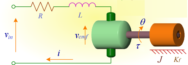
Figure 1. Equivalent model of DC motor
The torque  produced by a DC motor is directly proportional to the current
  flowing through its windings, as written in equation (1). Where
  is the armature constant that depends on the motor’s design and characteristics. This means that as the current increases, the torque output of the motor also increases.
| 
| (1) |
The electromotive force  induced in the armature of a DC motor is directly linear to the angular velocity of the motor. This relationship is a fundamental aspect of the motor’s operation and can be expressed by equation (2).
| 
| (2) |
where  is a constant electromotive force (CEF). The resultant torque of a motor, as described by Newton’s second law, depends on several factors, including the moment of inertia, and the angular acceleration. The relationship between moment of inertia
  , angular acceleration
  , and torque
  is denoted in equation
(3).
| 
| (3) |
where  is the friction constant. The armature in Figure 1 is a closed loop circuit, so Kirchoff’s voltage law can be applied. The resultant voltage in those loop can be written as in equation (4).
| 
| (4) |
By substituting equation (2) to equation (4), it is obtained equation (5).
| 
| (5) |
From the explanation above, two differential equations are obtained. The first differential equation is the electrical equation as written in equation (6). While the second equation is a mechanical equation as written in equation (7).
| 
| (6) |
| 
| (7) |
Those differential equation can be written in state space form, as follows
| 
| (8) |
| 
| (9) |
Equation equation (8) and equation (9) are functions in the continuous time domain. In its implementation, the PID control and Kalman filter are developed in the discrete time domain. For this reason, those state space needs to be converted into the discrete time domain. Discretization can be carried out using the forward discretization as follows
| 
| (10) |
| 
| (11) |
where Ts is sampling time. Forward discretization is easy to implement and computationally efficient, making
it suitable for resource-limited systems or real-time applications. However, the sampling time must be chosen
carefully. Inappropriate selection of sampling time affects the accuracy and stability of the system.
KALMAN FILTER DESIGN
The Kalman filter is a mathematical algorithm used in control systems and various other fields to estimate the state of a system in the presence of uncertain and noisy measurements. It produces variable estimates which values tend to be more precise than the measurement results.
The design of the Kalman filter depends on the plant model used. General form of plant model in discrete state space can be written as follows.
| 
| (12) |
where  is the transition matrix, describes the dynamics of the system.
  and
and  are the input matrix and control input, respectively. Meanwhile
  is process noise, with a covariance
  . The measurement data
from the sensor are represented using variable of  , as follows
| 
| (13) |
 is the output matrix and
  is the measurement noise, with covariance
  [16].
[16].
The Kalman filter consists of two main step: prediction and process. The algorithm and equations on each step can be seen in Figure 2. [16] provides details of the equations used. The Kalman filter uses these equations iteratively, making predictions of the system’s state and then updating these predictions with new measurements. It provides a statistically optimal estimate of the state by taking into account both the system dynamics and the measurement noise. The filter adapts to changes in the system over time and provides a way to improve state estimates in noisy environments.
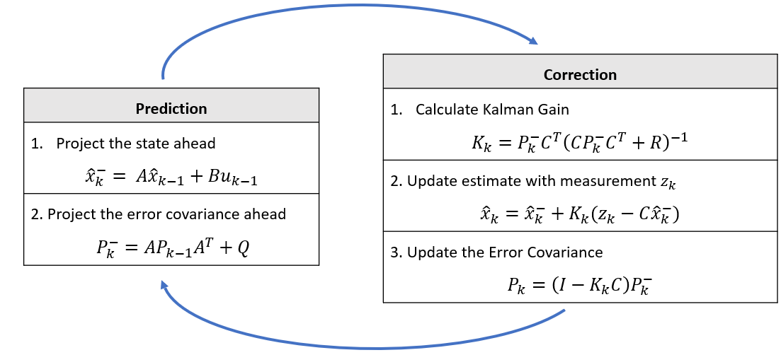
Figure 2. Kalman Filter Algorithm
Process noise covariance  and measurement noise covariance
  in 2 are selected and tuned for the
specific application. Process noise covariance  represents the uncertainty in the system model. It is related
to the prediction step of the filter. If the model in equation (10) and equation (11) accurately describes the dynamics of DC Motor then Q would be small. If the model is less accurate or the system is subject to significant disturbances, Q should be larger. Meanwhile measurement noise covariance R represents the uncertainty in the sensor measurements. If sensors are accurate and reliable, R should be small. If sensors are noisy, R should be larger.
CONTROL SYSTEM DESIGN
PID control is a versatile and widely used method for controlling DC motors, offering a good balance between simplicity and performance. Its advantages include ease of implementation, robustness, and the ability to eliminate steady-state error. However, PID controllers have limitations, particularly in systems with varying operating conditions, or significant noise. While other control strategies like state-space control [17][18], fuzzy logic controller [19][20], and model predictive control [21] offer enhanced performance in specific scenarios, they are generally more complex and may require more sophisticated design and tuning processes.
PID control consists of 3 parts, namely proportional control, integral control and derivative control. The equation of PID control is described in equation (14). The performance of PID control is determined by the selection of the  ,
,  and
and  parameters. Proper selection of PID parameters can significantly enhance the performance of the DC motor. On the other hand, unproper selection of PID parameters can lead the DC motor performance to instability. Various methods for tuning PID control have been developed, with one of the wellknown methods being the Ziegler-Nichols method. The Ziegler-Nichols has the advantages of simplicity, fast setup, and does not require in-depth analysis. In this research, the selection of PID parameters was carried out using the Ziegler-Nichols method and will be discussed in the next section
| 
| (14) |
with  is Control signal, output of PID control,
  is Error of the angular velocity,
  is Proportional Gain,
  is Integral Gain,
  is Derivative Gain. PID formula in equation (14) is in the continuous time domain. The DC motor in equation (10) and equation (11) are modeled in the for of discrete time. In order to have accurate control actions, the proposed controller needs to be brought into discrete time domain. PID control in the discrete time domain using forward discretization, as follows
| 
| (14) |
The proposed control system design is shown in Figure 3. Angular velocity of DC motor is assumed to have a measurement noise  with a covariance of R and a process constant error
  with a covariance of Q. The sensor measurement is used then as the filter input, in combination with
  input. The Kalman filter estimates the angular speed based on these two input parameters. The angular velocity estimation results are input for PID control, replacing the measurement results. Estimated angular velocity is supposed to reduce the influence of noise, and then the PID control system can produce precise control signals. The performance of the proposed control system will be validated through simulation.

Figure 3. Proposed Control Design
SETUP AND SIMULATION
The performance of the proposed control system is evaluated through simulation. Firstly, it is necessary to define parameters of DC motor, Kalman Filter and PID Control. DC motors are assumed to have parameters as in Table 1 [22].
Table 1. Parameters of DC motor
Parameter | Symbol | Value |
Armature Resistance | 
| 1 Ω |
Armature Inductance | 
| 0.5 H |
Armature Constant | 
| 0.01 Nm/A |
Constant of Electromotive Force | 
| 0.01 V/rad/sec |
Rotor Inertia | 
| 0.01 Kg2 |
Motor Viscous Constant | 
| 0.1 Nms |
PID parameters are derived using the Ziegler-Nichols method based on the system’s step response in open-loop conditions. This method involves applying a step input to the DC motor system and observing the output to derive the necessary PID parameters. First, apply a step input then record the DC motor’s output response over time. The open response of the DC motor is shown in Figure 4.
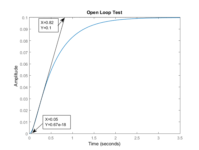
Figure 4. Open Loop Test
Based on the open loop response in Figure 4, it is obtained the delay time  and times constant
  of 0.05 and 0.77 second. delay time
  is the time between when the step input is applied and when the output starts to respond. While times constant
  is the time it takes for the output to reach 63.2% of its final value after the initial delay. In practice,
  is estimated from the slope of the response curve at the point of maximum steepness. Once
  and
and  are determined, the PID parameters can be calculate using the Ziegler-Nichols formula, as follows
Three scenarios of simulations were carried out to evaluate the performance of the proposed control system, namely ideal conditions, noisy condition, and filtered condition. In noisy condition and filtered condition, the system of DC motor is assumed to have a covariance error of  for process noise and
  for measurement noise. For certain applications,
  and
and  can be changed according to specific system conditions. This could be based on specifications, such as sensor accuracy and expected process variation. Then, the errors are assumed to be Additive White Gaussian Noise (AWGN). The performance of the control system in each condition is explained as follows
- Scenario 1 - Ideal Condition
First scenario, the DC motor is assumed to operate under ideal conditions, there is no process noise or measurement noise. The step response in nominal conditions can be seen in Figure 5. Figure 5 shows that the PID control works properly in this condition. There are no noises that interferes with the system performance. The control system is capable to track the references point well. The PID parameters in equation (16) to equation (18) result in optimal performance for the DC motor control system, with an Integral Absolute Error of 344.56 in ideal condition.
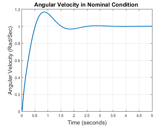
Figure 5. Angular velocity of DC motor in nominal condition
- Scenario 2 - Noisy Condition
In this scenario, the DC motor is assumed to have a covariance error of  for process noise and
  for measurement noise. The error is assumed to be Additive White Gaussian Noise (AWGN). The control system implemented does not yet involve the Kalman filter. The influence of process noise and measurement noise on DC motors will be discussed in this scenario. The step response of the DC motor control system can be seen in Figure 6.
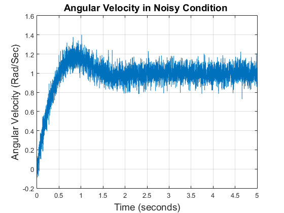
Figure 6. Angular velocity of DC motor in noisy condition
It can be seen in Figure 6, noise give the significant influence on the system. The PID control cannot generate control signals properly due to the presence of noise. The response continuously oscillates around the reference point. In real applications, this kind of response would have a negative impact on the hardware. The oscillatory response increases backlash in the gearbox and tooth wear in the transfer gear. Noises cannot be avoided, special treatment is needed to reduce the influence of the noises.
- Scenario 3 -Filtered Condition
The conditions in this scenario are the same as the previous scenario, there are process noise and measurement noise which interfere the performance of the DC motor. To estimate the angular velocity of the DC motor under noisy condition, Kalman filter is used in this scenario. The step response of this scenario can be seen in Figure 7. Figure 7 shows that the proposed Kalman filter based PID control reduces the influence of process noise and measurement noise. The proposed control system is capable to maintain the DC motor performance close to ideal conditions even though the noises take place.
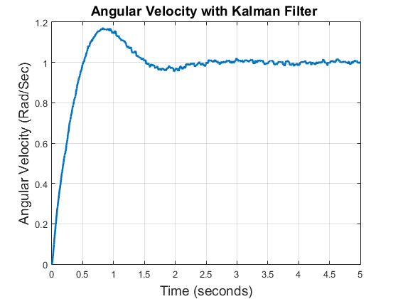
Figure 7. Angular velocity of DC motor in which Kalman Filter takes place
A comparison of the Integral Absolute Error (IAE) of all three scenarios can be seen in Table 2. Table 2 shows that process noise and measurement noise cause PID control performance to be not optimal. As evidenced, Scenario 2 has the highest IAE. By implementing the Kalman Filter, the influence of noise can be reduced so that PID control performance approaches ideal. It is proven by Scenario 3 having an IAE that is close to Scenario 1 (ideal conditions).
Table 2. Integral Absolute Error of All Three Scenarios
Scenarios | Integral Absolute Error (IAE) |
Scenario 1 (Nominal Condition ) | 344.56 |
Scenario 2 (Noisy Condition) | 517.27 |
Scenario 3 (Filtered Condition) | 345.25 |
CONCLUSION
Kalman filter-based PID control system for DC motors has been successfully developed. Measurement noise and process noise have a significant impact on the output response of the DC motor. Simulation results show that the PID control gives an Integral Absolute Error (IAE) of 344.5 in moninal condition. In the presence of noise, conventional PID control gives an IAE of 517.27. The noise gives oscillate responses continuously. While the Kalman filter-based PID control has better performance with an IAE of 345.25. Based on nominal conditions, Kalman filter-based PID control can reduce noise by 99.6% compared to conventional PID. These results show that the Kalman filter is effective in reducing noise. In general, the proposed control method is capable to maintain DC motor performance in noisy environments. For hardware implementation, the accuracy of the mathematical model and noise covariance need to be validated first to obtain an appropriate model.
REFERENCES
- A. Ma’arif, Iswanto, N. M. Raharja, P. Aditya Rosyady, A. R. Cahya Baswara and A. Anggari Nuryono, “Control of
DC Motor Using Proportional Integral Derivative (PID): Arduino Hardware Implementation,” 2020 2nd International Conference on Industrial Electrical and Electronics (ICIEE), pp. 74-78, 2020, https://doi.org/10.1109/ICIEE49813.2020.9277258. - R. K. Munje, P. P. Shinde and S. S. Kale, “Performance comparison of PI/PID controllers for DC motor,” 2014 Annual IEEE India Conference (INDICON), pp. 1-3, 2014, https://doi.org/10.1109/INDICON.2014.7030359.
- Y. Cerezo, I. Lopez, A. Cuesta and L. Grau, “Methodology for tuning a multirate PID controller based on ´
heuristic optimization,” 2009 35th Annual Conference of IEEE Industrial Electronics, pp. 1800-1804, 2009,
https://doi.org/10.1109/IECON.2009.5414840. - P. M. Meshram and R. G. Kanojiya, "Tuning of PID controller using Ziegler-Nichols method for speed control of DC motor," IEEE-International Conference On Advances In Engineering, Science And Management (ICAESM -2012), Nagapattinam, India, 2012, pp. 117-122, 2012, https://ieeexplore.ieee.org/abstract/document/6216102.
- A. Ma’arif, and N. R. Setiawan, “Control of DC Motor Using Integral State Feedback and Comparison with PID:
Simulation and Arduino Implementation,” Journal of Robotics and Control (JRC), vol. 2, no. 5, pp. 456-461, 2021, https://doi.org/10.18196/jrc.25122.
- S. Abedini and H. Zarabadipour, “Tuning of an optimal PID controller with iterative feedback tuning method for DC motor,” The 2nd International Conference on Control, Instrumentation and Automation, pp. 611-615, 2011, https://doi.org/10.1109/ICCIAutom.2011.6356728.
- A. Jaya, E. Purwanto, M. B. Fauziah, F. D. Murdianto, G. Prabowo and M. R. Rusli, "Design of PID-fuzzy for speed control of brushless DC motor in dynamic electric vehicle to improve steady-state performance," 2017 International Electronics Symposium on Engineering Technology and Applications (IES-ETA), pp. 179-184, 2017, https://doi.org/10.1109/ELECSYM.2017.8240399.
- X. -j. Ma, Y. Liu and L. Li, “Research and simulation on PID control method for Brushless DC Motor based on
genetic algorithm and BP neural network,” 2008 IEEE Vehicle Power and Propulsion Conference, pp. 1-4, 2008,
https://doi.org/10.1109/VPPC.2008.4677765. - E. W. Suseno,and A. Ma’arif, “Tuning of PID Controller Parameters with Genetic Algorithm Method on DC Motor,” International Journal of Robotics and Control Systems, vol. 1, no. 1, pp. 41-53, 2021,
https://doi.org/10.31763/ijrcs.v1i1.249. - E. S. Rahayu, A. Ma’arif, and A. C¸ akan, “Particle Swarm Optimization (PSO) Tuning of PID Control on DC Motor,” International Journal of Robotics and Control Systems, vol. 2, no. 2, pp. 435-447, 2022,
https://doi.org/10.31763/ijrcs.v2i2.476. - D. Sandoval, I. Soto and P. Adasme, “Control of direct current motor using Ant Colony optimization,” 2015 CHILEAN Conference on Electrical, Electronics Engineering, Information and Communication Technologies (CHILECON), pp. 79-82, 2015, https://doi.org/10.1109/Chilecon.2015.7400356.
- M. Iorgulescu, M. Alexandru and R. Beloiu, “Noise and vibration monitoring for diagnosis of DC motor’s faults,”
2012 13th International Conference on Optimization of Electrical and Electronic Equipment (OPTIM), pp. 724-729, 2012, https://doi.org/10.1109/OPTIM.2012.6231919. - D. Fodorean, C. Husar and C. Irimia, “Noise and vibration behavior evaluation of DC motor and PMSM in electric traction application,” 2016 International Symposium on Power Electronics, Electrical Drives, Automation and Motion (SPEEDAM), pp. 1184-1189, 2016, https://doi.org/10.1109/SPEEDAM.2016.7525931.
- A. Ma’arif, I. Iswanto, A. A. Nuryono, and R. I. Alfian, “Kalman Filter for Noise Reducer on Sensor Readings,” Signal and Image Processing Letters, vol. 1, no. 2, pp. 50-61, 2019, https://doi.org/10.31763/simple.v1i2.2.
- R. I. Alfian, A. Ma’arif, and S. Sunardi, “Noise Reduction in the Accelerometer and Gyroscope Sensor with the Kalman Filter Algorithm,” Journal of Robotics and Control (JRC), vol. 2, no. 3, pp. 180-189, 2021, https://doi.org/10.18196/jrc.2375.
- G. Welch and G. Bishop, “An introduction to the kalman filter,” Proc of SIGGRAPH, Course, vol. 8, no. 41, pp. 27599-23175, 2001, https://courses.cs.washington.edu/courses/cse571/03wi/notes/welchbishop-tutorial.pdf.
- J. Mehmood, M. Abid, M. S. Khan, A. Q. Khan and G. Mustafa, “Design of Speed Controller for a Brushless DC
Motor using Feedback Linearization,” 2021 International Bhurban Conference on Applied Sciences and Technologies (IBCAST), pp. 657-661, 2021, https://doi.org/10.1109/IBCAST51254.2021.9393215. - D. Wenxiang, L. Chengyang, Y. Jianyong, M. Dawei and L. Guigao, “Extended state observer based output feedback asymptotic tracking control of DC motors,” 2015 34th Chinese Control Conference (CCC), pp. 4262-4267, 2015, https://doi.org/10.1109/ChiCC.2015.7260298.
- W. Zhu, X. Ma, C. Sun and X. Niu, “Design of Fuzzy-PID Speed Controller for Brushless DC Motor,” 2019 3rd
International Conference on Electronic Information Technology and Computer Engineering (EITCE), pp. 1038-1042, 2019, https://doi.org/10.1109/EITCE47263.2019.9095061. - V. Verma and S. Chauhan, “Adaptive PID-Fuzzy Logic Controller for Brushless DC Motor,” 2019 3rd International conference on Electronics, Communication and Aerospace Technology (ICECA), pp. 445-449, 2019,
https://doi.org/10.1109/ICECA.2019.8821941. - S. Sahoo, B. Subudhi and G. Panda, “Optimal speed control of DC motor using linear quadratic regulator and model
predictive control,” 2015 International Conference on Energy, Power and Environment: Towards Sustainable Growth (ICEPE), pp. 1-5, 2015, https://doi.org/10.1109/EPETSG.2015.7510130. - N. D. Metha, A. M. Haque, and M. V. Makwana, “Controllers for Speed Control of Dc Motor Drives: Modeling
& Simulations,” International Journal of Applied Research in Science and Engineering, pp. 135–141, 2016, http://ijarse.org/images/scripts/201629.pdf.
AUTHOR BIOGRAPHY

| Nurman Setiawan obtained his bachelor degree from Department of Electrical Engineering, Faculty of Industrial Technology, Universitas Islam Indonesia in 2016. Later he got his master in Electrical Engineering from Universitas Gadjah Mada in 2019. He is curently lecturer in Department of Electrical Engineering Education, Universitas Negeri Yogyakarta, Indonesia. His research interest involves control system and robotics. He can be contacted at Email: nurman.setiawan@uny.ac.id. |
Implementation of Kalman Filter on PID Control System for DC Motor under Noisy Conditionm
(Nurman Setiawan)