Buletin Ilmiah Sarjana Teknik Elektro ISSN: 2685-9572
One-Shot Pulse Boost Converter-Based Inductor-Synchronized Piezoelectric Energy Harvester
Tole Sutikno 1, Muhammad Sukmadika Pradana 2, Anggit Pamungkas 3
1 Master of Electrical Engineering, Universitas Ahmad Dahlan, Indonesia
1,2 Department of Electrical Engineering, Universitas Ahmad Dahlan, Indonesia
3 Embedded Systems and Power Electronics Research Group, Indonesia
ARTICLE INFORMATION |
| ABSTRACT |
Article History: Submitted 03 February 2024 Revised 24 May 2024 Accepted 28 May 2024 |
| 
In this paper, we aim to review current methods of energy harvesting, focusing on piezoelectric energy. To optimize the use of piezoelectric devices in applications, a model is needed to observe the performance generated from piezoelectricity. To achieve better performance, the rectifier and capacitor systems are connected to a boost converter circuit. Another method is to use the Synchronized Switch Harvesting Inductor (SSHI) method. This method implements a stand-alone switching technique based on transistors and rectifier diodes and does not require an external power supply. This research creates an electric energy harvesting floor device by utilizing piezoelectricity in the form of a harvester, which aims to find out how piezoelectric works and to obtain a circuit with the most efficient characteristics as a piezoelectric power generator using SSHI and a boost converter. This study compares the characteristics of series, parallel, and series-parallel circuits on the floor of the most optimal piezoelectric energy harvester to generate voltage. The results of the data collection were based on the number of steps on the floor of the 16-piece piezoelectric energy harvester with a series-parallel circuit configuration connected with an SSHI circuit and without an SSHI circuit. In this test, the resulting voltage output is a DC voltage with an input step of 60 times the step on piezoelectricity. In this paper, an energy harvester using the SSHI circuit provides a more stable voltage on the harvester floor than a boost converter by providing 16 piezoelectric pieces arranged in series parallel. A floor energy harvester with a series-parallel configuration connected to SSHI gets the most optimal result compared to using a boost converter. |
Keywords: Piezoelectric; SSHI; Energy Harvesting; Converter; Boost Converter |
Corresponding Author: Tole Sutikno, Department of Electrical Engineering, Universitas Ahmad Dahlan, Indonesia. Email: tole@ee.uad.ac.id |
This work is licensed under a Creative Commons Attribution-Share Alike 4.0 
|
Document Citation: T. Sutikno, M. S. Pradana, A. Pamungkas, “One-Shot Pulse Boost Converter-Based Inductor-Synchronized Piezoelectric Energy Harvester,” Buletin Ilmiah Sarjana Teknik Elektro, vol. 6, no. 2, pp. 104-112, 2024, DOI: 10.12928/biste.v6i2.10020. |
- INTRODUCTION
Piezoelectricity is a phenomenon discovered by the Curie brothers in 1880 in which electricity is generated from crystals subjected to mechanical pressure [1][2] The word ipiezo itself is a Greek word which means pressure. The piezoelectric effect results from the linear electromechanical interaction between the mechanical and electrical parts present in the crystal [3]. Ipiezoelectric materials when they are not polarized because no pressure is applied. Meanwhile, after the piezoelectric gets pressure, the piezoelectric will experience polarization and generate electricity [4]–[6]. The ability of one piezoelectric chip is around 5µA for the output current and 5 VAC for the output voltage. In general, piezoelectric materials on the market are circular (piezoelectric disks) with different diameters.
Piezoelectric is a material which when given pressure or vibration will generate electrical energy, research related to piezoelectricity was also carried out by [7]–[10] to utilize vibrations obtained from mechanical energy. In research conducted [11][12] by utilizing piezoelectricity and boost converters as energy harvesters. To test this piezoelectricity with a pressure test and vibration test to see the effect on the surface area on its performance in producing electrical energy. This research is expected to assist engineers in choosing the right piezoelectric for manufacturing energy harvesting systems in order to produce greater electrical energy [13][14].
Synchronized Switch Harvesters on Inductor (SSHI) [15]–[18] is one of the most efficient interfaces for pulsed piezoelectric energy harvesters. In research on SSHI [19]–[21] it can show the ability to increase high voltage. To activate the piezoelectric SSHI must issue a higher voltage than the capacitor [22]–[24]. In this research, a low power Energy Harvesting Floor was created which can later be utilized and developed to be used to supply low power electronic devices. This research creates an electrical energy harvesting floor device by utilizing piezoelectricity as a harvester that is integrated with the SSHI circuit, by conducting piezoelectric circuit experiments in series, parallel and series-parallel configurations to obtain the most optimal voltage output.
- METHODS
In this study the design of a piezoelectric energy harvester utilizes the energy obtained from footsteps by utilizing piezoelectricity as the main component. To maximize the energy harvested, the use of the SSHI series is very helpful in optimizing the energy generated from the harvesting process from the harvester floor. Therefore, a circuit design needs to be created and implemented in this system to maximize the harvested energy from the harvesting floor.
- Piezoelectric
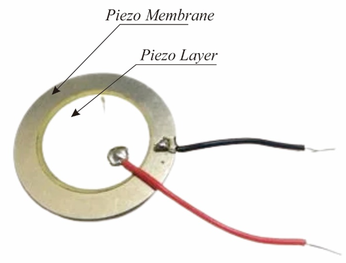
Piezoelectric is formed from a ceramic material that has been polarized so that it is negatively charged which forms electrodes attached to opposite sides, to produce an electric material field that can change due to the influence of mechanical forces. Linear electromechanical interaction between the mechanical and electrical parts present in the crystal can produce the piezoelectric effect. In this study using the piezoelectric in Figure 1, which is connected in series and parallel attached to polyfoam, and plywood as a cover later when the human footrest is not damaged.

Figure 1. Piezoelectric
- Synchronized Switch Harvesters on Inductor (SSHI)
SSHI is one of the most efficient interfaces for piezoelectric energy harvesters with vibration, the SSHI circuit has several components that will be connected to each other to be able to influence each time a current will enter the SSHI circuit so that the current waveform is more stable, components that are interconnected in the SSHI circuit namely the Inductor winding, Mosfet IRF530N can be seen in Figure 2.
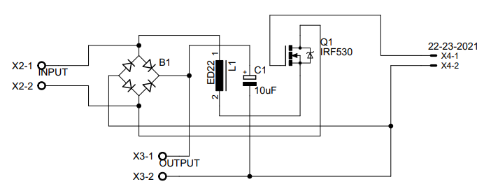
Figure 2. SSHI circuit schematic
- Block Diagram of the SSHI Connected System
In the block diagram of the process system Figure 3, the floor of the electric energy harvester uses a piezoelectric connected to SSHI, the vibration generated from mechanical energy is converted by the piezoelectric into AC electrical energy, the use of the SSHI circuit in the harvesting system to optimize the energy conversion generated from piezoelectricity maximally and more efficiently. In the SSHI series there is the NE555 module as a generator pulse circuit for switching. From the conversion process through the SSHI circuit, it is then directed so that the resulting AC voltage is converted to a DC voltage that can be consumed by low-power DC loads.

Figure 3. System block diagram of a floor SSHI-connected piezoelectric energy harvester
- Block Diagram of the SSHI Unconnected System
In the system block diagram Figure 4, the floor process of the electric energy harvester uses a piezoelectric not connected to SSHI, in this system the voltage generated from the mechanical energy process resulting from the piezoelectric footing is directly forwarded to the rectifier to convert AC to DC voltage which can then be consumed by low-power DC loads.

Figure 4. System block diagram of an SSHI disconnected piezoelectric energy harvester floor
- System Flowchart
In the flowchart of this study, two approaches are used. The first floor system is a piezoelectric energy harvester that is connected to the SSHI circuit and the second is without being connected to SSHI as shown in Figure 5. In Figure 5, the system flow diagram (a) is a harvester system that is connected to SSHI which is synchronized with the NE555 module and aligned with a rectifier for AC to DC voltage conversion whose conversion results can be consumed by low-power DC loads.
In Figure 5 the system flow diagram (b) is a harvester system that is not connected to SSHI. The voltage generated from the piezoelectric is then directly rectified by the rectifier to convert the harvested AC voltage to be converted into DC voltage and can be consumed by low-power DC loads. In this study, the data collection method used a trial method for several circuits, namely series, parallel and series parallel connected to SSHI and a circuit without SSHI by trying several human weights and the number of footings.
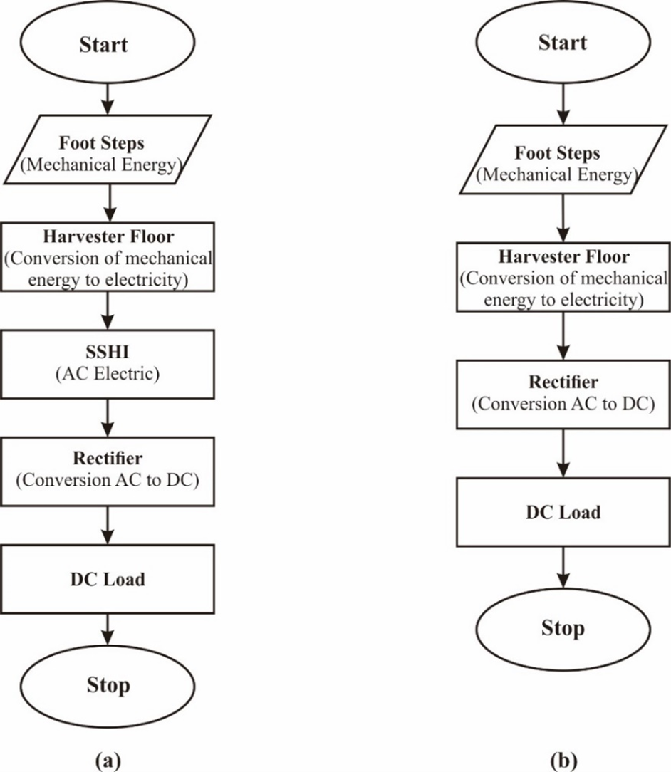
Figure 5. Flowchart of SSHI-connected and disconnected harvester systems
- Piezoelectric Energy Harvester Floor Test
This test has several stages, namely:
- Testing the AC-DC voltage of 8 and 16 piezoelectric pieces based on human weight, testing the AC-DC voltage on this piezoelectric circuit will be tested in series, parallel and series parallel, by connecting 8 piezoelectric pieces arranged in series, parallel and series parallel, tests are carried out by tapping a person's feet on the floor of a piezoelectric energy harvester, data collection was carried out on 10 people with different weights, namely 47kg, 50kg, 53kg, 55kg, 58kg, 60kg, 68kg, 70kg, 72kg and 98kg.
- Testing the NE555 Module. In testing the NE555 Module, a frequency matching is carried out that will be used on the NE555 Module. This test uses an oscilloscope to display frequency waves.
- Testing the DC Voltage of 16 pieces of piezoelectric based on the number of footings, this test was carried out by looking at the voltage generated by the piezoelectric energy harvester floor with the number of footings 4x, 8x, 12x, 16x, 20x, 24x, 28x, 32x, 36x, 40x, 44x, 48x, 52x, 56x and 60x footing each data capture.
- RESULT AND DISCUSSION
The results of this study are to determine the high efficiency and maximum power extraction from the floor of the piezoelectric energy harvester using SSHI and not using SSHI, and to know the characteristics of the circuit and the work of the piezoelectric as a generator of electrical energy. In this test, the focus is on finding voltage data with the most efficient circuit on the floor of a piezoelectric energy harvester, which is connected to the SSHI circuit and which is not connected to SSHI. In this study, the test is to see a comparison of the circuit on the floor of the piezoelectric energy harvester, namely:
- Testing the AC-DC voltage of 8 piezoelectric plates.
- Testing the AC-DC voltage of 16 piezoelectric plates.
- Testing the DC voltage of 16 plates without connecting SSHI.
- Testing the DC voltage of 16 pieces connected to SSHI.
Comparison Results of AC-DC Circuit with 8 Piezoelectric Chips
The results of data collection in this test are based on the human body weight on the floor of the piezoelectric energy harvester, in this test it compares the AC-DC voltage output from 8 piezoelectric chips which are arranged in series, parallel and series-parallel. Comparison of the voltage results is presented using the graphs in Figure 6 and Figure 7.
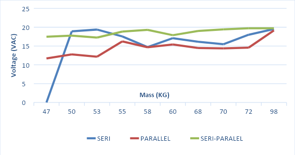
Figure 6. Graph 8 AC Voltage Piezeoelectric Chips
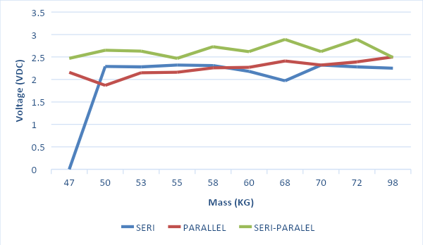
Figure 7. Graph 8 Piezoelectric Chip DC Voltage
In Figure 6 and Figure 7, the graph compares series, parallel and series-parallel circuits using 8 piezoelectric chips. The results obtained are piezoelectric AC and DC voltage outputs with series, parallel and sri-parallel circuit configurations. The graph shows the fluctuating output value due to the resulting footing load having varying values. Based on the three circuit configurations used, the most optimal voltage output is piezoelectric with parallel and series-parallel circuit configurations.
AC-DC Circuit Comparison of 16 Piezoelectric Chips
The data collection results in this test are based on the human body weight on the floor of the piezoelectric energy harvester. This test compares the AC-DC voltage output from 16 piezoelectric chips arranged in series, parallel, and series-parallel. A comparison of the voltage results is presented using the graphs in Figure 8 and Figure 9.
Figure 8 and Figure 9 are piezoelectric comparison charts for 16 pieces with a series-parallel circuit configuration. The experiment was carried out by observing the results of AC and DC voltage output with various input load loads. The results obtained show that the AC output voltage graph has a fluctuating value. The step load input also affects the voltage output. The heavier the load given to the piezoelectric, the greater the voltage produced. Meanwhile, the DC voltage output on piezoelectrics has a smaller value than the AC voltage output with the same load input but has better voltage output stability.
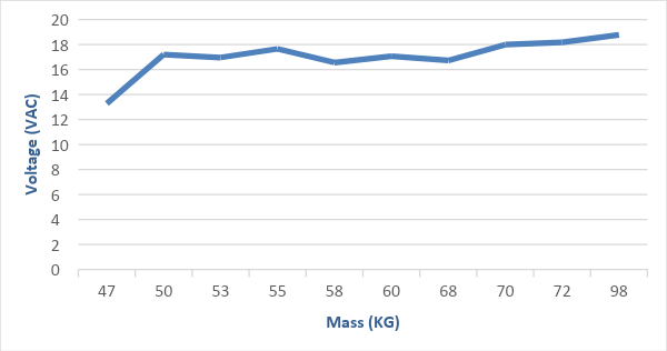
Figure 8. Graph 16 AC Voltage Piezoelectric Chips
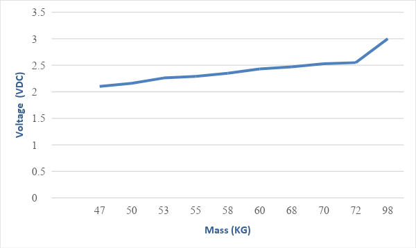
Figure 9. Graph 16 Piezoelectric Chip DC Voltage
DC Voltage Test Results for 16 Chips without Connecting and Connecting SSHI
In this test, the data collection results were based on the number of steps on the floor of the 16-piece piezeoelectric energy harvester with a series-parallel circuit configuration connected with an SSHI circuit and without an SSHI circuit. In this test, the resulting voltage output is a DC voltage with an input step of 60 times the step on piezoelectricity. The results obtained in this experiment are presented in the form of a stress graph, as shown in Figure 10 and Figure 11.
Figure 10 is data from a piezoelectric experiment with a series-parallel configuration without using an additional SSHI circuit. The results obtained show that the output voltage graph increases in direct proportion to the increase in the number of steps given to the piezoelectric but has a less stable increase. Meanwhile, in the graph in Figure 11, which is data from a piezoelectric experiment with a series-parallel configuration with the addition of the SSHI circuit, it has a constant voltage output graph with a stable increase in proportion to the increase in the number of steps given to the piezoelectric.
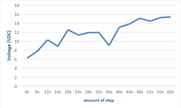
Figure 10. Graph 16 Piezoelectric Chip DC Voltage Not Connected to SSHI
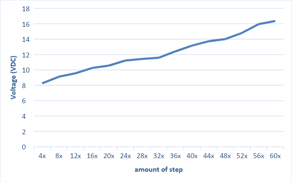
Figure 11. Graph 16 Piezoelectric Chip DC Voltage SSHI Connected
- CONCLUSIONS
The piezoelectric energy harvester floor is energy that produces low voltage, even though it has low voltage the piezoelectric energy harvester floor has the advantage of being free of air pollution and does not depend on weather changes, in this study it was concluded that the piezoelectric energy harvester floor produces electrical energy by providing mechanical energy in the form of pressure or vibration, the circuit on the floor of the piezoelectric energy harvester with the most optimal voltage output characteristics, namely a series-parallel circuit connected to SSHI by testing provides a number of footings, SSHI provides a more stable voltage compared to using a Boost Converter, by providing 16 piezoelectric chips on the harvesting floor connected to SSHI, the weight and the number of footings on the floor of the piezoelectric energy harvester produce different voltages, the voltage will continue to increase when the number of footings and weight increases. It is hoped that this research can further develop a series of piezoelectric energy harvesting floors that are connected to SSHI and Boost Converter, which is hoped to produce energy harvesting floors on a larger scale so that their utilization is maximized.
ACKNOWLEDGEMENT
Thank you to the Embedded Systems and Power Electronics Research Group (ESPERG) for supporting this research.
REFERENCES
- S. Gao, Y. Lin and J. Zhu, "The Effect of Mounting Structure and Piezoelectric Pressure Probe Sensor Incident Angle on the Free-Field Measurement," in IEEE Sensors Journal, vol. 19, no. 17, pp. 7226-7233, 2019, https://doi.org/10.1109/JSEN.2019.2913680.
- R. A. Cooper and R. Cooper, “Rehabilitation Engineering: A perspective on the past 40-years and thoughts for the future,” Medical engineering & physics, vol. 72, pp. 3-12, 2019, https://doi.org/10.1016/j.medengphy.2019.08.011.
- Z. Zhang, H. Xiang, and L. Tang, “Modeling, analysis and comparison of four charging interface circuits for piezoelectric energy harvesting,” Mechanical Systems and Signal Processing, vol. 152, p. 107476, 2021, https://doi.org/10.1016/j.ymssp.2020.107476.
- A. Behera and A. Behera, “Energy harvesting and storing materials,” Advanced Materials: An Introduction to Modern Materials Science, pp. 507-555, 2022, https://doi.org/10.1007/978-3-030-80359-9_15.
- B. Maamer, A. Boughamoura, A. M. F. El-Bab, L. A. Francis, and F. Tounsi, “A review on design improvements and techniques for mechanical energy harvesting using piezoelectric and electromagnetic schemes,” Energy Conversion and Management, vol. 199, p. 111973, 2019, https://doi.org/10.1016/j.enconman.2019.111973.
- R. R. Moussa, W. S. Ismaeel, and M. M. Solban, “Energy generation in public buildings using piezoelectric flooring tiles; A case study of a metro station,” Sustainable Cities and Society, vol. 77, p. 103555, 2022, https://doi.org/10.1016/j.scs.2021.103555.
- P. A. Alekseev, V. A. Sharov, B. R. Borodin, M. S. Dunaevskiy, R. R. Reznik, and G. E. Cirlin, “Effect of the uniaxial compression on the GaAs nanowire solar cell,” Micromachines, vol. 11, no. 6, p. 581, 2020, https://doi.org/10.3390/mi11060581.
- R. J. Ganesh, D. B. Shanmugam, S. Munusamy and T. Karthikeyan, “Experimental study on footstep power generation system using piezoelectric sensor,” Materials Today: Proceedings, vol. 45, pp. 1633-1637, 2021, https://doi.org/10.1016/j.matpr.2020.08.474.
- M. R. Sarker, S. Julai, M. F. M. Sabri, S. M. Said, M. M. Islam, and M. Tahir, “Review of piezoelectric energy harvesting system and application of optimization techniques to enhance the performance of the harvesting system,” Sensors and Actuators A: Physical, vol. 300, p. 111634, 2019, https://doi.org/10.1016/j.sna.2019.111634.
- B. Bao and Q. Wang, “Small‐scale experimental study on the optimisation of a rooftop rainwater energy harvester using electromagnetic generators in light rains,” International Journal of Energy Research, vol. 44, no. 13, pp. 10778-10796, 2020, https://doi.org/10.1002/er.5726.
- P. Visconti, V. M. Mastronardi, M. De Vittorio and R. De Fazio, "A Waste-produced Floor with Solar and Mechanical Energy Harvesters to Power Charging Stations or OLED Lighting Systems," 2022 7th International Conference on Smart and Sustainable Technologies (SpliTech), pp. 1-6, 2022, https://doi.org/10.23919/SpliTech55088.2022.9854363.
- L. Wang, R. P. Burgos and A. Vazquez Carazo, "Design and Analysis of Tunable Piezoelectric Transformer Based DC/DC Converter with AC Output Inductor," 2020 IEEE Applied Power Electronics Conference and Exposition (APEC), pp. 1398-1403, 2020, https://doi.org/10.1109/APEC39645.2020.9124475.
- P. Yingyong, P. Thainiramit, S. Jayasvasti, N. Thanach-Issarasak, and D. Isarakorn, “Evaluation of harvesting energy from pedestrians using piezoelectric floor tile energy harvester,” Sensors and Actuators A: Physical, vol. 331, p. 113035, 2021, https://doi.org/10.1016/j.sna.2021.113035.
- J. Choi, I. Jung, and C. Y. Kang, “A brief review of sound energy harvesting,” Nano energy, vol. 56, pp. 169-183, 2019, https://doi.org/10.1016/j.nanoen.2018.11.036.
- Z. Long, P. Li, J. Chen, H. S. -H. Chung and Z. Yang, "Self-Powered Single-Inductor Rectifier-Less SSHI Array Interface With the MPPT Technique for Piezoelectric Energy Harvesting," in IEEE Transactions on Industrial Electronics, vol. 69, no. 10, pp. 10172-10181, 2022, https://doi.org/10.1109/TIE.2021.3139175.
- S. Xi, W. Li, J. Guo and J. Liang, "A Self-Powered Piezoelectric Energy Harvesting Interface Circuit Based on Adaptive SSHI with Fully Integrated Switch Control," 2020 IEEE International Symposium on Circuits and Systems (ISCAS), pp. 1-4, 2020, https://doi.org/10.1109/ISCAS45731.2020.9180969.
- M. Meng, D. Wang, B. D. Truong, S. Trolier-McKinstry, S. Roundy and M. Kiani, "A Multi-Beam Shared-Inductor Reconfigurable Voltage/SECE Mode Piezoelectric Energy Harvesting Interface Circuit," in IEEE Transactions on Biomedical Circuits and Systems, vol. 13, no. 6, pp. 1277-1287, 2019, https://doi.org/10.1109/TBCAS.2019.2942261.
- A. Morel, A. Brenes, D. Gibus, E. Lefeuvre, P. Gasnier, G. Pillonnet, and A. Badel, “A comparative study of electrical interfaces for tunable piezoelectric vibration energy harvesting,” Smart Materials and Structures, vol. 31, no. 4, p. 045016, 2022, https://doi.org/10.1088/1361-665X/ac54e8.
- B. Pollet, G. Despesse and F. Costa, "A New Non-Isolated Low-Power Inductorless Piezoelectric DC–DC Converter," in IEEE Transactions on Power Electronics, vol. 34, no. 11, pp. 11002-11013, 2019, https://doi.org/10.1109/TPEL.2019.2900526.
- E. Roshandel and J. He, "High Efficiency High Step-Up DC-DC Converter to Drive Piezo-Electric Transmitters," 2019 IEEE Industry Applications Society Annual Meeting, Baltimore, MD, USA, 2019, pp. 1-16, 2019, https://doi.org/10.1109/IAS.2019.8911977.
- J. Wen, N. Wan, R. Wang, S. Chen, J. Zheng and J. Li, "A Novel Linear Walking Type Piezoelectric Actuator Based on the Parasitic Motion of Flexure Mechanisms," in IEEE Access, vol. 7, pp. 25908-25914, 2019, https://doi.org/10.1109/ACCESS.2019.2900381.
- A. Mahajan, A. Goel, and A. Verma, “A review on energy harvesting based piezoelectric system,” Materials Today: Proceedings, vol. 43, pp. 65-73, 2021, https://doi.org/10.1016/j.matpr.2020.11.210.
- P. R. Prasad, A. Bhanuja, L. Bhavani, N. Bhoomika and B. Srinivas, "Power Generation Through Footsteps Using Piezoelectric Sensors Along with GPS Tracking," 2019 4th International Conference on Recent Trends on Electronics, Information, Communication & Technology (RTEICT), pp. 1499-1504, 2019, https://doi.org/10.1109/RTEICT46194.2019.9016865.
- L. Wu and D. S. Ha, "A Self-Powered Piezoelectric Energy Harvesting Circuit With an Optimal Flipping Time SSHI and Maximum Power Point Tracking," in IEEE Transactions on Circuits and Systems II: Express Briefs, vol. 66, no. 10, pp. 1758-1762, 2019, https://doi.org/10.1109/TCSII.2019.2924963.
AUTHOR BIOGRAPHY

| Tole Sutikno     is a lecturer in Master Program of Electrical Engineering, Faculty of Industrial Technology, Universitas Ahmad Dahlan, Indonesia. He received his B.Eng., M.Eng. and Ph.D. degrees in Electrical Engineering from Universitas Diponegoro, Universitas Gadjah Mada and Universiti Teknologi Malaysia, in 1999, 2004 and 2016, respectively. He has been an Associate Professor in UAD, Yogyakarta, Indonesia since 2008. He is currently an Editor-in-Chief of the TELKOMNIKA and the Head of the Embedded Systems and Power Electronics Research Group (ESPERG). His research interests include the field of digital design, industrial applications, industrial electronics, industrial informatics, power electronics, motor drives, renewable energy, FPGA applications, embedded system, artificial intelligence, intelligent control, information technology and digital library. He can be contacted at email: tole@ee.uad.ac.id. is a lecturer in Master Program of Electrical Engineering, Faculty of Industrial Technology, Universitas Ahmad Dahlan, Indonesia. He received his B.Eng., M.Eng. and Ph.D. degrees in Electrical Engineering from Universitas Diponegoro, Universitas Gadjah Mada and Universiti Teknologi Malaysia, in 1999, 2004 and 2016, respectively. He has been an Associate Professor in UAD, Yogyakarta, Indonesia since 2008. He is currently an Editor-in-Chief of the TELKOMNIKA and the Head of the Embedded Systems and Power Electronics Research Group (ESPERG). His research interests include the field of digital design, industrial applications, industrial electronics, industrial informatics, power electronics, motor drives, renewable energy, FPGA applications, embedded system, artificial intelligence, intelligent control, information technology and digital library. He can be contacted at email: tole@ee.uad.ac.id. |
|
|

| Muhammad Sukmadika Pradana is received his B. Eng. in electrical engineering from Universitas Ahmad Dahlan, Indonesia, in 2023. His research interests include, renewable energy technology, robotics and the Internet of Things. He can be contacted at email: muhammad1800022042@webmail.uad.ac.id. |
|
|

| Anggit Pamungkas     received his B.Eng. degree in Electrical Engineering from Universitas Ahmad Dahlan, Yogyakarta, Indonesia in 2018. After receiving his degree, he became a member of the Embedded Systems and Power Electronics Research Group (ESPERG). His research interests include power electronics, renewable energy technology, robotics and the Internet of Things. He can be contacted at email: anggitpamungkas17@gmail.com. received his B.Eng. degree in Electrical Engineering from Universitas Ahmad Dahlan, Yogyakarta, Indonesia in 2018. After receiving his degree, he became a member of the Embedded Systems and Power Electronics Research Group (ESPERG). His research interests include power electronics, renewable energy technology, robotics and the Internet of Things. He can be contacted at email: anggitpamungkas17@gmail.com. |
One-Shot Pulse Boost Converter-Based Inductor-Synchronized Piezoelectric Energy Harvester
(Tole Sutikno)