Buletin Ilmiah Sarjana Teknik Elektro ISSN: 2685-9572
Hybrid System Prototype for Dam Water Level Control System to Irrigating Rice Fields
Agung Wahyu Hidayat, Indah Sulistiyowati, Arief Wicaksono, Syamsudduha Syahrorini
Department of Electrical Engineering, Universitas Muhammadiyah Sidoarjo, East Java, Indonesia
ARTICLE INFORMATION |
| ABSTRACT |
Article History: Submitted 02 January 2024 Revised 12 February 2024 Accepted 19 February 2024 |
| 
Naturally, one of the causes of crop failure in agriculture is flooding brought on by unchecked water overflow, particularly during the rainy season. Crop failure is a common source of complaints from farmers because, in addition to making it harder for them to sell their harvests, it decreases the price at which rice is sold to customers, which reduces the amount of people who purchase rice. This project aims to develop a hybrid dam water level control system prototype for paddy field irrigation. In this instance, the innovative flood monitoring and control system integrates Blynk as a user interface that can be accessible via software, along with an ESP 32 monitoring unit and a NodeMCU 8266 controller. like smartphone devices. The ESP 32 controls servo motor 1 to open the dam door in the event of flooding. In addition, the ESP 32 monitors the dam's water level using the I2C LCD and alerts the user with a bell. The NodeMCU 8266 functions as a link to the ultrasonic sensor to relay the water level data to the ESP 32. Through the Blynk application, the user can manually control Servo motor 2 to open and close the dam door with configurable water level limitations. The results of the studies indicate that this system functions flawlessly, from setting up a warning system to connecting tools. The system may be manually operated by making use of microcontroller technology. |
Keywords: Automatic Dam; Blynk, ESP 32; Dam Warning System; NodeMCU 8266 |
Corresponding Author: Indah Sulistiyowati, Department of Electrical Engineering, Universitas Muhammadiyah Sidoarjo, East Java, Indonesia. Email: indah_sulistiyowati@umsida.ac .id |
This work is licensed under a Creative Commons Attribution-Share Alike 4.0 
|
Document Citation: A.W. Hidayat, I. Sulistiyowati, A.Wicaksono, and S. Syahrorini “Hybrid System Prototype for Dam Water Level Control System to Irigatting Rice Fields,” Buletin Ilmiah Sarjana Teknik Elektro, vol. 6, no. 1, pp. 25-33, 2024, DOI: 10.12928/biste.v6i1.10016. |
- INTRODUCTION
Water is a necessary element for all living things. Non-living resources that can be replenished are water resources. These days, water is an important resource required for human life and all of its activities [1]. Thin management of natural resources is the only way to stop the destruction of ecosystems. As natural resources gain in value, this is done to protect the environment. Earth's current inhabitants have shown that the planet can maintain life. The reason for this is that for basic needs, humans depend on specific natural resources. A vital component of human survival, water resources also play a significant role in elevating the standard of human life on Earth. In addition to humans, all other living species on Earth need on water to thrive. In addition, that is the nature of humanity in the past and now [2].
This time, the issues raised by water spilling over rice fields close to dams will be discussed [3]. Flooding is one of the effects; vast sums of money are needed to repair the damage it causes, and it frequently disrupts residents' lives economically. For instance, flooding could cause farmers' crops to fail [4]. Indonesia is particularly susceptible to flooding due to its high rainfall levels. Although flooding is an inevitable occurrence, it can be lessened by adding sluice gates to reservoirs or dams. A dam is a construction placed across a river with the purpose of raising the water level of the river. Moreover, floodgates on dams can be opened and closed continuously or gradually for a variety of reasons [5].
This research appears to be proceeding nicely, based on earlier work "Application of PID Controller to Water Level Control System Using MATLAB" by Salma Rahmani, Suci Aulia Rosana, and Ghina Hanin Tian in 2022 [6]. Not only does the Thingspeak website offer features for monitoring up to eight locations at once on a single server, but previous research "Design of Prototype Monitoring of Dam Water Level Based on Internet of Things" by A. Samrul Ilmun Nafik also describes a monitoring system that can successfully monitor three locations on one server [7]. However, there are still issues that arise when there are no symptoms of flooding but the water level is above the capacity. Furthermore, there is no automated control system on the dam door, no remote monitoring of the sensor's accuracy, and no use of the Blynk application to deliver notifications via the Internet of Things [8].
A prototype system of a dam water level control system for arresting with a hybrid system is built in this thesis research in response to these issues. It is envisaged that this technique will make it easier to adjust water level both manually and automatically. Countermeasures, or preparations, to deal with the actual flood are crucial since a dam breach could result in a massive flood if there is an excess of water in the dam and it is not immediately emptied [9]. Signals to the ESP 32 and NodeMCU 8266 can be sent via Blynk communication, which can also be utilized to regulate the amount of water entering the rice fields [10],[11]. The Ultrasonic Sensor measures the height of the water discharge; if the water exceeds the set point that we have set, the buzzer will sound as a sign of flooding in the rice field area. Next, the servo motor opens and closes the entrance to the water course to the rice fields. The LCD reads active and inactive components [12]. With the use of this tool, farmers who had trouble harvesting their rice are no longer faced with crop failures and may find a solution to their issues. In order to minimize the amount of loss, this tool's influence helps the community and government respond to disaster occurrences more swiftly and precisely [13]. Additionally, to assist agricultural households in reducing the chance that flooding could cause crop failure in rice fields [14].
- METHODS
The Research and Development (R&D) research method was employed in this study to expand upon and modernize earlier research [15]. Research and development (R&D) is a technique used to create specific goods or equipment that can assist farmers in reducing their risk of flooding [16],[17]. Three procedures will be covered in this chapter: creating block diagrams to illustrate how the tool operates; creating flowcharts to give a program overview; and designing wiring diagrams to determine the flow of installed electrical circuits [18]. Each process has a different purpose, but in the end, these three processes will be continuous with the ultimate goal of creating a prototype that can work effectively so that it is useful for the community [19].
- System Design
The design of this tool consists of three parts. The first part is drawing a block diagram that shows the input, processing, and output components of the system along with their connections. The subsequent action
The first stage of the system design process is the wiring design phase, which entails laying out the components of the system and their connections. Drawing a flow chart that illustrates the system's workflow and the relationships between its many components is the third phase. Together, these three sections provide a thorough overview of the architecture and operation of the system [20].
- Block Diagram System
To facilitate tool design and fabrication in the current device, a block diagram of the entire system as a whole is made. Below is a block diagram of the Prototype Dam Water Level Control System for Irrigating Rice Fields with a Hybrid System. as shown in Figure 1.
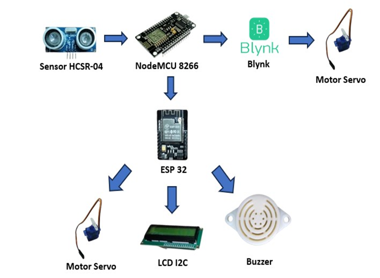
Figure 1. Block diagram system
- Wiring Design
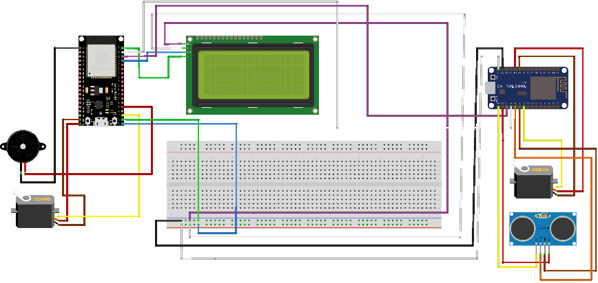
The wiring diagram in Figure 2 is a wiring circuit used in this study, in the picture it appears that all components used as input and output are connected to the microcontroller, the microcontroller used is ESP 32 and NodeMCU 8266. components used as input and output are connected by a microcontroller, the microcontroller used is ESP 32 and NodeMCU 8266. All components used must be well connected so that the tools used can run optimally.
In Figure 2 there are several components used with the following uses:
- An ultrasonic sensor that measures the dam's water level and transmits data signals to NodeMCu 8266.
- The NdeMCU 8266 data signal is received by the ESP 32 microcontroller, which is used to monitor the water level in the dam. The ESP 32 then transmits the data results to the LCD, buzzer, and servo motor output.
- The NodeMCU 8266 microcontroller functions as the circuit's brain, processing data received by the sensor before sending it to the sensor's component parts and finally the output parts. To connect to Blynk, this microcontroller will be wired up to a Wi-Fi network.
- A water level sensor using ultrasonic technology that sends data signals to NodeMCu 8266.
- The ESP 32 microcontroller, which is used to track the water level in the dam, receives the NdeMCU 8266 data signal. After that, the ESP 32 sends the data results as an output to the servo motor, LCD, and buzzer.
- As the brains of the circuit, the NodeMCU 8266 microcontroller processes the data that is received by the sensor and then sends it to the component parts of the sensor and the output portions. We will link this microcontroller to a Wi-Fi network in order to connect it to blynk.
The Table 1 demonstrates how Vin and ground from the inbound nodemcu are connected to the project board, which has numerous inputs and outputs. Nodemcu pins D7 and D8 are connected to Trig and Echo in the ultrasonic sensor, and D5 is connected to the servo motor. Output a from the servo motor leads to the NodeMCU 8266, which is 3V and Ground. Output a from nodemcu goes to input a Vin and Ground ultrasonic. After that, RX and TX nodemcu are connected to ESP 32.
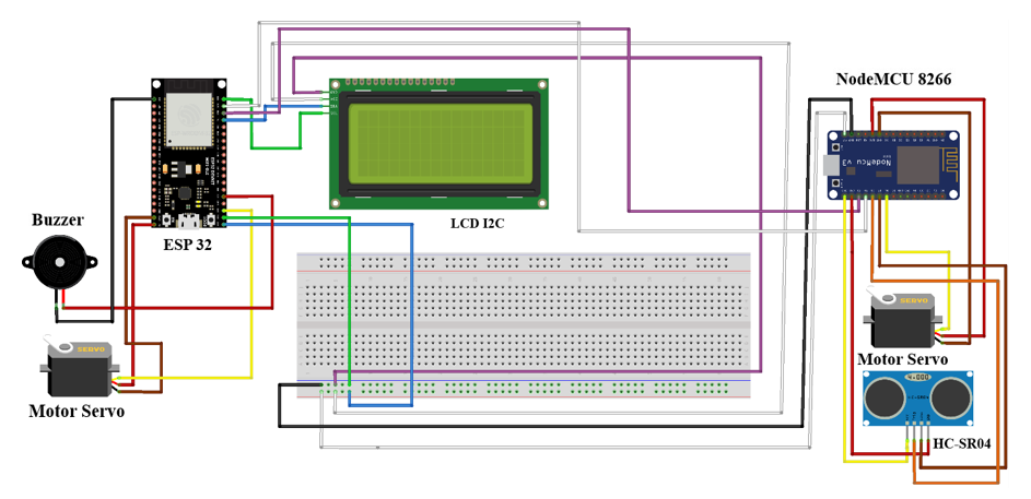
Figure 2. Wiring design
Table 1. NodeMCU Port Usage
No | NodeMCU Port | Usage |
1. | Vin | Project Board |
2. | GND | Project Board |
3. | 3V | Motor servo |
4. | GND | Motor servo |
5. | 3V | Vin Ultrasonic |
6. | GND | Ground Ultrasonic |
7. | RX | RX ESP 32 |
8. | TX | TX ESP 32 |
9. | D7 | Trig Ultrasonic |
10. | D8 | Echo Ultrasonic |
11. | D5 | Motor Servo |
- System Flowchart
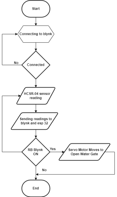
The flowchart, which is intended to make the research process easier, is a research flowchart from the start to the finish. Two flowcharts, one for the monitoring system and one for the control system, are included in this study. Using NodeMCU as the controller, Figure 3 depicts a control system flowchart. It starts by turning on the Android internet connection and connecting it to Blynk. If it is connected, the ultrasonic sensor will then read and send the reading to both Blynk and ESP 32. When everything is connected, the next thing to do is switch on RB Blynk. If it is, the servo motor will cause the dam sluice gate to open.
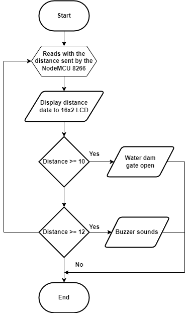
There are two flowcharts in this research one for the monitoring system and one for the control system. The second flowchart, shown in Figure 4, is a monitoring system flowchart using an ESP 32 microcontroller. The ESP 32 will then read the data from the NodeMCU and send it to the LCD to display the distance data. Once it does, we will measure it by adding water to the dam prototype. At ten centimeters' distance, We'll be aware of the servo motor's response when it opens the dam sluice gate. It is now the Buzzer's turn to work, sounding an alert that there will be a flood in the rice field region once the water has risen above the prior 12-cm barrier.
| 
|
Figure 3. First flowchart program control system | Figure 4. Second flowchart program monitoring system |
- RESULT AND DISCUSSION
The results of the research realization of the prototype of the dam water level system for irrigating rice fields with a hybrid system can be seen in Figure 5. All components used will be described by numbering as follows: 1. Ultrasonic Sensor, 2. ESP 32, 3. NodeMCU 8266, 4. LCD I2C, 5. Buzzer, 6.Servo Motor.
Figure 5. Result of tool realization
The two steps below can be used to operate the prototype microcontroller:
The first control phase (manual)
- The user can turn on the Wi-Fi network that the microcontroller was previously connected to.
- To connect the microcontroller to a power source, use the USB cord.
- After that, the user links the microcontroller and Blynk software.
- To verify whether the device is connected or online, the user can choose the monitoring option once they are in the Blynk application. Should this not be the case, Blynk will be unable to control the servo motor in an orderly fashion.
- The monitoring then has a writing that says "ON" to open and "OFF" to close.
- For instance, if the user presses ON, the servo motor will open the water dam door if the user presses OFF, the servo motor will close once more.
The second step for Monitoring (Automatic)
- The user has the option to activate the Wi-Fi network that was previously linked to the microcontroller.
- Use the USB cable to supply electricity to the microcontroller.
- After that, the user can confirm that the LCD turns on correctly and shows the distance to the dam's water level.
- After everything is powered on and connected, users can fill the prototype with water until the LCD displays the water level of the dam at a distance of 10 cm. This allows them to determine whether the prototype is functioning properly or not.
- The user can then see that the servo motor will automatically open the dam door after displaying a water level distance of 10 cm.
- A buzzer component will ring to alert the user that the water level has exceeded the capacity if they wish to go beyond the prototype's water size, say by adding a 12-cm water level gap.
- As an example, this prototype's height of 15 cm is produced by an ultrasonic sensor. The system is configured to allow a maximum of 10 cm to pass between the water level and the ultrasonic sensor if the user wishes to go beyond this distance, it can be as much as 11 or 12 cm. However, certain parts of the system will function as a warning system, such as the buzzer component, which signals that there will be a flood due to the water level exceeding the designated capacity.
- Testing of Wi-Fi Connection to ESP 32
Testing the Wi-Fi connection to the ESP 32 is done between 4 and 5 seconds, and the results are displayed in Table 2. The research findings indicate that the ESP 32 is capable of creating a stable wireless network.
Table 2. Testing Wi-Fi connection to ESP 32
Testing to- | Wi-Fi ESP 32 | Accuracy (%) |
Condition | Waiting Time (s) |
1st Test | Connected | 5 | Medium |
2nd Test | Connected | 6 | Medium |
3rd Test | Connected | 5 | Medium |
4th Test | Connected | 5 | Medium |
5th Test | Connected | 6 | Medium |
- Testing of Blynk Connection to NodeMCU 8266
Testing the Blynk connection to the NodeMCU 8266 is done between 4 and 5 seconds, and the results are displayed in Table 3. The research findings indicate that the NodeMCU 8266 is capable of creating a stable wireless network.
Table 3. Testing Blynk connection to NodeMCU ESP8266
Testing to- | Blynk NodeMCU 8266 | Accuracy (%) |
Condition | Waiting Time (s) |
1st Test | Connected | 4 | Medium |
2nd Test | Connected | 6 | Medium |
3rd Test | Connected | 4 | Medium |
4th Test | Connected | 3 | Medium |
5th Test | Connected | 7 | Medium |
- Ultrasonic Sensor Testing
The ultrasonic sensor has been tested five times as shown in Table 4 and each time the results are in order and the sensor feed value, This shows that the sensor is working as it should and has gone through testing and validation as shown in Table 4.
Table 4. Testing Ultrasonic Sensor
No. | Ultrasonic Sensor | Ruler Manual | Error (%) |
1. | 1 cm | 4.3 cm | 3.3 % |
2. | 2 cm | 5.1 cm | 3.1 % |
3. | 3 cm | 6.2 cm | 3.2 % |
4. | 4 cm | 7.3 cm | 3.3 % |
5. | 5 cm | 8.3 cm | 3.3 % |
- Connection Testing of Blynk Module With Servo Motor
It is evident from Table 5 that the Blynk application functions as intended when we simply press the button to activate the servo motor. The application has been tested five times. Each time the test results match the input value of the application.
Table 5. Connection Testing Of Blynk Module With Servo Motor
No. | Blynk (Application) | State of Servo Motor |
ON | OFF | ON | OFF |
1. | ON | - | ON | - |
2. | - | OFF | - | OFF |
3. | ON | - | ON | - |
4. | - | OFF | - | OFF |
5. | ON | - | ON | - |
- Testing The Dam Warning System
A buzzer will sound when the ultrasonic sensor's distance reading exceeds 10 cm, according to the findings of five tests conducted on the device. Table 6 displays continuous positive findings from device tests. Everything functions as intended because all servo test commands and realizations are accurate.
Table 6. Testing The Dam Warning System
No | Parameter | System Work | The system Does Not Work | Description |
1. | 7 cm | - | Not Working | OFF |
2. | 8 cm | - | Not Working | OFF |
3. | 9 cm | - | Not Working | OFF |
4. | 10 cm | Work | - | ON |
5. | 11 cm | Work | - | ON |
- Testing The Connection of The Ultrasonic Sensor With The Servo Motor and LCD
The servo will move to open when the ultrasonic sensor reading system, which has undergone five testing, detects a water level of 10 cm, as shown on the LCD. According to the device test findings displayed in Table 7, every command consistently yields positive results.
Table 7. Testing The Connection Of The Ultrasonic Sensor With The Servo Motor And LCD
No | Ultrasonic Sensor Readings (cm) | LCD I2C | Servo Motor State |
ON | OFF | ON | OFF |
1 | 8 | ON | - | - | OFF |
2 | 9 | ON | - | - | OFF |
3 | 10 | ON | - | ON | - |
4 | 11 | ON | - | ON | - |
5 | 12 | ON | - | ON | - |
- Blynk
Users can simply control and see the system's work process in this study by utilizing the Blynk application as an interface. In order to connect the NodeMCU 8266 microcontroller and ESP 32 so that it can blink, the user needs first activate wifi before launching the blynk application. The user merely needs to push the ON button to open or OFF button to close Blynk as a manual system in accordance with the desired command once the microcontroller and Blynk have been connected via wifi. and the user can also observe the system operating automatically by using the Android user's display screen. For example, in the picture below, the Blynk display indicates the number 12, which indicates that the height has exceeded the maximum limit. By using Blynk for monitoring, the user can more easily determine the distance to the dam's water level, and the microcontroller will then react and operate in accordance with the given command. Figure 6 shows the test findings.
Figure 6. Menu in Blynk
- CONCLUSIONS
The test results show that the internet connection test functions as intended, and the device may be linked to allow Blynk commands to be delivered to NodeMCU and ESP 32. Previous research found that the testing procedure was not completed because the monitoring method was not carried out automatically. Current study has completed testing, but the prototype still experiences a little delay when water is added. The ultrasonic sensor's testing results show that, despite errors caused by water shocks that interfere with sensor readings and servo motor functioning, the sensor is still able to measure the distance of the pre-filled water. This study has a significant impact on farmers' ability to avoid crop failure. and might eventually support the economy. Research suggestions aimed at generating further ideas or tactics to improve this instrument and lessen the constraints that have been found. To prevent shocks during water filling, for instance, which could affect sensor readings, consider using a different sensor or filtration method.
REFERENCES
- S. A. Northey, G. M. Mudd, T. T. Werner, N. Haque, and M. Yellishetty, “Sustainable water management and improved corporate reporting in mining,” Water Resources and Industry, vol. 21, p. 100104, 2019, https://doi.org/10.1016/j.wri.2018.100104.
- G. Cheng and Y. Yan, “Sociodemographic, health-related, and social predictors of subjective well-being among Chinese oldest-old: a national community-based cohort study,” BMC geriatrics, vol. 21, no. 1, pp. 1-13, 2021, https://doi.org/10.1186/s12877-021-02071-7.
- M. Khairudin, M. L. Hakim, O. A. Rahmawan, W. N. Alfiati, A. Widowati, and E. Prasetyo, “Design of automatic water level control system using fuzzy logic,” In Journal of Physics: Conference Series, vol. 2406, no. 1, p. 012006, 2022, https://doi.org/10.1088/1742-6596/2406/1/012006.
- Y. Anwar, I. Setyasih, and M. V. R. Ningrum, “Multi-ethnic communities adaptation to flooding in the north samarinda sub-district, samarinda city, east kalimantan province, indonesia. In IOP Conference Series: Earth and Environmental Science, vol. 683, no. 1, p. 012079, 2021, https://doi.org/10.1088/1755-1315/683/1/012079.
- S. S. Baek, J. Pyo, and J. A. Chun, “Prediction of water level and water quality using a CNN-LSTM combined deep learning approach,” Water, vol. 12, no. 12, p. 3399, 2020, https://doi.org/10.3390/w12123399.
- H. Efheij, A. Albagul and N. Ammar Albraiki, "Comparison of Model Predictive Control and PID Controller in Real Time Process Control System," 2019 19th International Conference on Sciences and Techniques of Automatic Control and Computer Engineering (STA), pp. 64-69, 2019, https://doi.org/10.1109/STA.2019.8717271.
- Y. Saragih, J. H. Prima Silaban, H. Aliya Roostiani and S. A. Elisabet, "Design of Automatic Water Flood Control and Monitoring Systems in Reservoirs Based on Internet of Things (IoT)," 2020 3rd International Conference on Mechanical, Electronics, Computer, and Industrial Technology (MECnIT), pp. 30-35, 2020, https://doi.org/10.1109/MECnIT48290.2020.9166593.
- I. García-Magariño, F. González-Landero, R. Amariglio and J. Lloret, "Collaboration of Smart IoT Devices Exemplified With Smart Cupboards," in IEEE Access, vol. 7, pp. 9881-9892, 2019, https://doi.org/10.1109/ACCESS.2018.2890393.
- S. Yahya, S. W. Jadmiko, K. Wijayanto, and A. R. A. Tahtawi, “Design and implementation of training module for control liquid level on tank using PID method based PLC,” In IOP Conference Series: Materials Science and Engineering, vol. 830, no. 3, p. 032065, 2020, https://doi.org/10.1088/1757-899X/830/3/032065.
- F. B. Poyen, A. Ghosh, P. Kundu, S. Hazra and N. Sengupta, "Prototype Model Design of Automatic Irrigation Controller," in IEEE Transactions on Instrumentation and Measurement, vol. 70, pp. 1-17, no. 9502217, 2021, https://doi.org/10.1109/TIM.2020.3031760.
- S. Syahrorini, A. Rifai, D. H. R. Saputra, and A. Ahfas, “Design smart chicken cage based on internet of things,” In IOP Conference Series: Earth and Environmental Science, vol. 519, no. 1, p. 012014, 2020, https://doi.org/10.1088/1755-1315/519/1/012014.
- B. Dewantara, I. Sulistiyowati, and J. Jamaaluddin, “Automatic Fish Feeder and Telegram Based Aquarium Water Level Monitoring,” Bul. Ilm. Sarj. Tek. Elektro, vol. 5, no. 1, pp. 98–107, 2023, https://doi.org/10.12928/biste.v5i1.7575.
- V. P. Kour and S. Arora, "Recent Developments of the Internet of Things in Agriculture: A Survey," in IEEE Access, vol. 8, pp. 129924-129957, 2020, https://doi.org/10.1109/ACCESS.2020.3009298.
- M. A. Iqbal, A. Abbas, S. A. A. Naqvi, M. Rizwan, A. Samie, and U. I. Ahmed, “Drivers of farm households’ perceived risk sources and factors affecting uptake of mitigation strategies in Punjab Pakistan: Implications for sustainable agriculture,” Sustainability, vol. 12, no. 23, p. 9895, 2020, https://doi.org/10.3390/su12239895.
- V. A. Safitri, L. Sari, and R. R. Gamayuni, “Research and Development, Environmental Investments, to Eco-Efficiency, and Firm Value,” Indones. J. Account. Res., vol. 22, no. 03, pp. 377–396, 2019, http://doi.org/10.33312/ijar.446.
- W. A. Jabbar et al., "Design and Fabrication of Smart Home With Internet of Things Enabled Automation System," in IEEE Access, vol. 7, pp. 144059-144074, 2019, https://doi.org/10.1109/ACCESS.2019.2942846.
- J. Baptista, M. K. Stein, S. Klein, M. B. Watson-Manheim, and J. Lee, “Digital work and organisational transformation: Emergent Digital/Human work configurations in modern organisations,” The Journal of Strategic Information Systems, vol. 29, no. 2, p. 101618, 2020, https://doi.org/10.1016/j.jsis.2020.101618.
- M. I. Hidayatullah , I. Sulistiyowati, and D. H. R. Saputra, “Automatic Roof Prototype on Aviary with Telegram Based Monitoring,” Buletin Ilmiah Sarjana Teknik Elektro, vol. 5, no. 2, pp. 239–250, 2023, https://doi.org/10.12928/biste.v5i2.8214.
- M. A. Juliyanto, I. Sulistiyowati, A. Ahfas, M. A. Juliyanto, I. Sulistiyowati, and A. Ahfas, “Design of Turbine Aerator with Remote Control and Internet of Things (IoT)-Based Water pH Monitoring,” Bul. Ilm. Sarj. Tek. Elektro, vol. 5, no. 1, pp. 156–166, 2023, https://doi.org/10.12928/biste.v5i1.7863.
- C. D. Setyawan and A. Wisaksono, “Body Posture Position Alarm Prototype Based on NodeMCU ESP8266,” Buletin Ilmiah Sarjana Teknik Elektro, vol. 5, no. 4, pp. 614–622, 2023, https://doi.org/10.12928/biste.v5i4.9543.
AUTHOR BIOGRAPHY

| Agung Wahyu Hidayat is a student at Muhammadiyah University of Sidoarjo majoring in electrical engineering. He was born in Pasuruan on December 22, 2001 and became a martial arts coach at the loyal heart terate squad, In his learning process on campus he has experience as chief assistant in the electrical engineering laboratory at the university and is a student who has participated in the independent campus program, namely student exchange in Asia University. |
|
|

| Indah Sulistiyowati is a researcher who specializes in Renewable Energy Power Systems and Control Systems. Completed her master’s degree at Institut Teknologi Sepuluh Nopember majoring in Control System Electrical Engineering Subsidiary, and now is a lecturer at Universitas Muhammadiyah Sidoarjo. |
|
|
| Arief Wisaksono born in Ponorogo in April 1968. My undergraduate degree in Electrical Engineering and my Master’s degree is in Management, graduated in 2010. My area of research interest is Microprocessors, internet of thinking, information systems and machine learning, my profession as well as my way of life as a teacher at the Faculty of Electrical Engineering, Muhammadiyah University of Sidoarjo. |
|
|

| Syamsudduha Syahrorini is an active lecturer in the Department of Electrical Engineering, Faculty of Science and Technology, Muhammadiyah University of Sidoarjo. She received a Bachelor's Degree from Muhammadiyah University of Malang, a Master’s Degree from Sepuluh Nopember Institute of Technology, and a Doctoral's degree from Brawijaya University. Some of the previous research she has done are: IOT-Based Sumo Robot Control Using Blynk Software (2023), Training on processing household organic waste into eco enzyme at 'Aisyiyah Sidoarjo Orphanage (2022), K-Nearest Neighbor Algorithm to Identify Cucumber Maturity with Extraction of One-Order Statistical Features and Gray- Level Co-Occurrence (2021), and many more. |
Hybrid System Prototype for Dam Water Level Control System to Irrigating Rice Fields
(Agung Wahyu Hidayat)